

Dual Input Multi-stage 12V
In-vehicle Battery Charger
BCDC1225D, BCDC1240D

1
THE BCDC1225D & BCDC1240D
The BCDC1225D/BCDC1240D Dual Input In-vehicle Battery Chargers feature technology designed
to charge your auxiliary batteries to 100%, regardless of their type or size.
The Dual Input In-vehicle Battery Chargers also feature a Maximum Power Point Tracking (MPPT)
solar regulator. The unit will always take as much power from the Solar input as it can before
supplementing that power, up to the maximum rated output, from Vehicle power input.
The Dual Input In-vehicle Battery Chargers are suitable for all common types of automotive lead
acid batteries and LiFePO
4
lithium type batteries.
WARNING & SAFETY INSTRUCTIONS
SAVE THESE INSTRUCTIONS - This manual contains IMPORTANT SAFETY INSTRUCTIONS for the
BCDC1225D/BCDC1240D battery chargers.
DO NOT OPERATE THE BATTERY CHARGER UNLESS YOU HAVE READ AND UNDERSTOOD THIS MANUAL
AND THE CHARGER IS INSTALLED AS PER THESE INSTALLATION INSTRUCTIONS. REDARC RECOMMENDS
THAT THE CHARGER BE INSTALLED BY A SUITABLY QUALIFIED PERSON.
RISK OF EXPLOSIVE GASES:
WORKING IN VICINITY OF A LEAD-ACID BATTERY IS DANGEROUS. BATTERIES GENERATE EXPLOSIVE
GASES DURING NORMAL OPERATION. FOR THIS REASON, IT IS OF UTMOST IMPORTANCE THAT YOU
FOLLOW THE INSTRUCTIONS WHEN INSTALLING AND USING THE CHARGER.
1. The Battery Charger should not be used by persons (including children) with reduced physical, sensory or mental
capabilities, or lack of experience and knowledge, unless they are supervised or have been instructed on how to
use the appliance by a person responsible for their safety. Children should be supervised to ensure that they do
not play with the Battery Charger.
2. Do NOT alter or disassemble the Battery Charger under any circumstances. All faulty units must be returned to
REDARC for repair. Incorrect handling or reassembly may result in a risk of electric shock or fi re and may void the
unit warranty.
3. Only use the Battery Charger for charging Standard Automotive Lead Acid, Calcium Content, Gel, AGM, SLI, Deep
Cycle or Lithium Iron Phosphate type 12V batteries.
4. Check the manufacturers data for your battery and ensure that the ‘Maximum’ voltage of the profi le you select
does not exceed the manufacturers recommended maximum charging voltage. If the ‘Maximum’ voltage is too
high for your battery type, please select another charging profi le.
5. When using the Battery Charger to charge a Lithium Iron Phosphate battery, only batteries that feature an inbuilt
battery management system featuring inbuilt under and over voltage protection and cell balancing are suitable.
6. The Battery Charger is not intended to supply power to a low voltage electrical system other than to charge a
battery.
7. Cable and fuse sizes are specifi ed by various codes and standards which depend on the type of vehicle the Battery
Charger is installed into. Selecting the wrong cable or fuse size could result in harm to the installer or user and/or
damage to the Battery Charger or other equipment installed in the system. The installer is responsible for ensuring
that the correct cable and fuse sizes are used when installing this Battery Charger.
8. NEVER smoke or allow a spark or fl ame in vicinity of battery or engine. This may cause the battery to explode.
9. PERSONAL SAFETY PRECAUTIONS
To assist with the safe operation and use of the Battery Charger when connected to the battery:
a) Wear complete eye protection and clothing protection. Avoid touching eyes while working near a battery.
b) If battery acid contacts your skin or clothing, remove the affected clothing and wash the affected area of your skin
immediately with soap and water. If battery acid enters your eye, immediately fl ood the eye with running cold
water for at least 10 minutes and seek medical assistance immediately.
SAL.FOR.Instruction Manual.BCDCD – Version 2

2
CONTENTS
Warnings and Safety Instructions 01
Contents 02
Specifi cations 02
1 Product Function 03
1. Display Panel 03
2. Charge Profi le LEDs 04
3. Charge Status LEDs 04
1. Solar & Vehicle LEDs 04
2. Stage LED 04
3. Charging Process 05
4. Turn ON/OFF Thresholds 06
5. Error Codes 06
2 Installation 07
1. Install Location 07
2. Charge Profi le Selection (ORANGE Wire) 08
3. Input Trigger Settings (BLUE Wire) 09
4. Cable Sizing 09
5. Wiring 10
6. Fusing 10
7. Typical Setup 11
3 Troubleshooting 12
4 Frequently Asked Questions 13
5 Two Year Warranty 14
SPECIFICATIONS
Part Number BCDC1225D BCDC1240D
Continuous Current Rating 25A 40A
Vehicle Input Fuse Rating
40A (Not Supplied)
REDARC FK40 recommended
60A (Not supplied)
REDARC FK60 recommended
Output Fuse Rating
Output Power 375W 600W
Vehicle Input Voltage Range 9-32V
Solar Input Voltage Range 9-32V
Output Battery Type Standard Lead Acid, Calcium content, Gel, AGM or LiFePO
4
type only
Charging Profi le ABCLi
- Maximum Voltage
(refer to section 1.2.1) 14.6V 15.0V 15.1V 14.6V
- Float Voltage 13.3V N/A
No Load Current <100mA
Standby Current <8mA
Ambient Temperature 0°C to 80°C
Minimum O/P Battery Volts 4.2V
Weight 850g
Dimensions 165x120x37mm
Warranty 2 years
Standards RCM, AS/NZS CISPR11:2004
3
1 PRODUCT FUNCTION
The BCDC1225D/BCDC1240D is a three-stage, 12V DC-DC battery charger that operates
from an alternator input of 12V or 24V and a 12V nominal solar panel input. The input
voltage of the BCDC1225D/BCDC1240D can be above, below or equal to the output
voltage making it ideal for charging an auxiliary 12V battery where the distance from the
main battery may cause a signifi cant voltage drop. The BCDC1225D/BCDC1240D is also
designed to isolate the main battery from the auxiliary battery, to avoid over-discharging
the main battery.
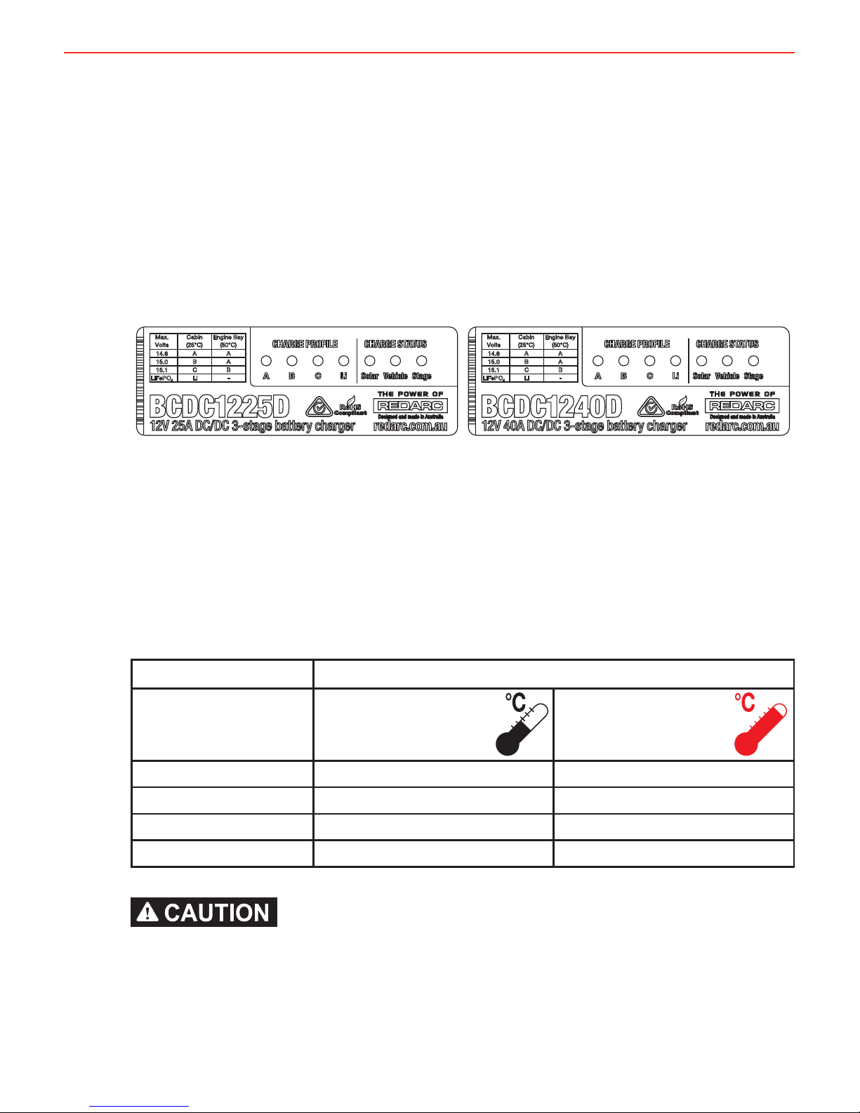
1.1 Display Panel
The front panel features 7 LEDs to display the charge profi le and charge status.
Figure 1.1.1 - The BCDC1225D and BCDC1240D Front Panels
1.2 Charge Profi le LEDs
The Dual Input In-vehicle Battery Chargers feature 4 different charging profi les
designed to suit your battery’s charging requirements. It is recommended to
refer to the charging specifi cations stated by the battery manufacturer and the
installation temperature chart below (Figure 1.2.1) before selecting the profi le for
your installation.
Auxiliary Battery Location
Maximum Battery
Voltage Specifi cation
Cabin
Install
Engine Bay
Install
14.6 AA
15.0 BA
15.1 CB
LiFePO
4
Li Not Recommended
Check the manufacturer’s data for your battery and ensure that the ‘Maximum’ voltage
of the profi le you select does not exceed the manufacturer’s recommended maximum
charging voltage. If the ‘Maximum’ voltage is too high for your battery type, please select
another charging profi le.
25 50
+
Figure 1.2.1 - Charge Profi le Selection

4
1 PRODUCT FUNCTION
1.3 Charge Status LEDs
The Charge Status LEDs indicate to the user which inputs are available and
what stage of the charge process is currently in.
1.3.1 Solar & Vehicle LEDs
The Solar and Vehicle LEDs will be ON when the input is available and in use
and OFF when the input is not available or not in use.
If both LEDs are ON, both input sources are available and in use.
The Dual Input In-vehicle Battery Charger uses Green Power Priority technology.
This means the unit will always supply as much power as possible from the
Solar input before supplementing this with power from the Vehicle input, to the
maximum output of the unit or required by the battery at the time.
1.3.2 Stage LED
The Stage LED indicates the charge profi le stage. With either A, B or C Profi les
selected the charger will output a 3-Stage Lead Acid type charging profi le with
Boost, Absorption and Float Stages. When the Li Profi le is selected the charger
will output a 2-Stage LiFePO
4
type charging profi le with Constant Current and
Constant Voltage stages.
Figure 1.3.2.1 outlines the LED sequences which indicate these stages and
fi gure 1.3.3.1 explains the Charging Process.
LED Sequence A, B or C Profi le Stage Li Profi le Stage
Continuous
OFF (No Output) OFF (No Output)
Continuous
Boost Constant Current
2 Seconds
Absorption
Constant Voltage
2 Seconds
Float
Figure 1.3.2.1 - Charge Stage LED Sequences

5
1 PRODUCT FUNCTION
1.3.3 Charging Process
A, B or C Profi les
When the Charger is turned on, it will move into the Boost stage. The Boost stage
maintains a constant current until the battery voltage reaches its Absorption Voltage.
The current in Boost stage may vary during operation in order to maintain safe
operating temperature, or to limit the difference between input and output voltages.
The Charger will then move to Absorption stage which maintains a constant voltage
level for a predetermined period of time or until the current being drawn by the
output battery drops to less than 4A for 30 seconds; after which the Charger will
enter Float stage.
Float stage maintains 13.3V on the output battery, keeping the battery topped up.
This counteracts the battery’s self discharging or loads applied to the battery. When
the battery loses charge, the Charger will move back into the Boost stage.
Li Profi le
When the Charger is turned on, it will move into the
Constant Current
stage. This
stage maintains a constant current until the battery voltage reaches its set point. The
current may vary during operation in order to maintain safe operating temperature,
or to limit the difference between input and output voltage.
The Charger will then move to
Constant Voltage
stage. This stage maintains 14.5V
on the output battery, keeping the battery topped up. This stage also counteracts
the battery’s self discharging. When a load applied to the battery causes it to lose
charge, the Charger will move back into the
Constant Current
stage.
When using the Battery Charger to charge a Lithium Iron Phosphate battery, only
batteries that feature an inbuilt battery management system featuring inbuilt under and
over voltage protection and cell balancing are suitable.
Voltage A, B or C
FloatAbsorptionBoost
Current
Charging Process
Voltage Li
Constant Current Constant Voltage
Figure 1.3.3.1 - Charging Process

6
1 PRODUCT FUNCTION
1.4 Turn On/Off Thresholds
Input 12V Vehicle Input 24V Vehicle Input Solar
Input Trigger
Settings
Standard
Low
Voltage
Standard
Low
Voltage
N/A
Input
Open Circuit
Low voltage
conditions *
1
Turn ON
ABOVE
13.2V 12.0V 26.4V 24.0V 9.0V
Turn OFF
BELOW
12.7V 11.9V 25.4V 23.8V 9.0V
Input
Loaded Low
voltage
conditions*
2
Turn OFF instantly
BELOW
8.0V 16.0V 9.0V
Turn OFF after 20s
BELOW
9.0V 18.0V N/A
Input
Over voltage
shutdown
Turn ON
BELOW
15.5V 32V
Turn OFF instantly
ABOVE
16.0V 32.5V 33.0V
Turn OFF after 20s
ABOVE
15.6V 32.1V N/A
Output
Under voltage
shutdown *
1
Shutdown if Output Battery < 4V
1.5 Error Codes
In the event of a fault with the unit installation, either battery or solar panel, ALL
the LEDs on the unit will fl ash to indicate the fault type. Flashing sequences are
described in the table below.
LED State Description
1 fl ash (1 fl ash followed by 3.5 second off) Internal Hardware Fault
2 fl ash (2 fl ash followed by 3.5 second off) Unit under temp fault
3 fl ash (3 fl ash followed by 3.5 second off) Unit over temp fault
4 fl ash (4 fl ash followed by 3.5 second off) Output Battery Fault (Volts too high)
5 fl ash (5 fl ash followed by 3.5 second off) Input under voltage (Battery)
6 fl ash (6 fl ash followed by 3.5 second off) Input over voltage (Battery or Solar panel)
*1Tested every 100 Seconds.
*
2
Constantly tested.

7
2 INSTALLATION
2.1 Install Location
The charger is suitable for mounting in the cabin of the vehicle, along a chassis
rail or in the engine bay (ensure the unit does not become covered by a build
up of mud or other). It is important to ensure the charger is mounted as close
as possible to the battery being charged (auxiliary battery). Certain batteries
are better suited to each of these types of installations so it is important to
select the correct battery type. For more information consult your battery
manufacturer’s specifi cations.
Lithium type (LiFePO
4
) batteries are not suitable for engine bay installations.
Refer to fi gure 1.2.1 for selecting the best Charge Profi le for your installation.
The charger should be mounted in any orientation (so that the front decal is
visible) using the 4 mounting tabs provided on the heatsink (refer fi gure 2.1.1)
using suitably sized screws.
The unit will operate optimally below 55°C with good airfl ow. At higher
temperatures the unit will de-rate output current up to 80°C where the unit will
turn OFF.
Figure 2.1.1 - Mounting the Charger

8
2 INSTALLATION
2.2 Charge Profi le Selection (ORANGE Wire)
The ORANGE wire is used to select the Maximum output voltage. This is achieved
by connecting in the following way:
To select Profi le A leave the ORANGE wire disconnected. This will set the
Maximum voltage to 14.6V.
To select Profi le B connect the ORANGE wire to Common Ground. This will set
the Maximum voltage to 15.0V.
To select Profi le C connect the ORANGE wire to the RED wire (Input source
positive). This will set the Maximum voltage to 15.1V.
To select the Li Profi le connect the ORANGE wire to the GREEN wire (LED
output). This will set the charger to Lithium mode.
Check the manufacturer’s data for your battery and ensure that the Maximum voltage
of the profi le you select does not exceed the manufacturer’s recommended maximum
charging voltage. If the Maximum voltage is too high for your battery type, please select
another charging profi le.
Not
Connected
Orange Wire
Orange Wire
Orange Wire
Red Wire
Input
Source
Positive
Midi
Fuse
Green Wire
Optional
LED
Orange Wire
Figure 2.2.1 - Charge Profi le Selection

9
2 INSTALLATION
2.3 Input Trigger Settings (BLUE Wire)
The BLUE wire is used to select between the Standard turn ON trigger settings
and the Low Voltage turn ON trigger settings (suitable for Variable Voltage and
Smart Alternators) on the Vehicle Input.
Standard trigger settings: Leave the BLUE wire disconnected.
This will set the trigger settings to 13.2V turn ON and 12.7V turn OFF for a 12V
installation or 26.4V turn ON and 25.4V turn OFF for a 24V installation.
Low Voltage trigger settings: Connect the BLUE wire to the Vehicle Ignition.
This will set the trigger settings to 12.0V turn ON and 11.9V turn OFF when
Ignition is ON for a 12V installation or 24.0V turn ON and 23.8V turn OFF
when Ignition is ON for a 24V installation.
Standard Low Voltage
Vehicle
Ignition
Blue Wire
Not
Connected
Blue Wire
Figure 2.3.1 - Setting the Input Trigger Settings
2.4 Cable sizing
Below is a table outlining the required cable size for a given cable install length.
Please refer to this table for Vehicle Input, Solar Input, Ground and Battery Output
cable thickness requirements.
Always choose a wire diameter equal to or greater than what is specifi ed below.
Part Number Cable Install Length
(m)
Recommended Wire
Size (mm²)
Closest (BAE, B&S,
AWG)
BCDC1225D 1 - 5 7.71 8
5 - 9 13.56 6
BCDC1240D 1 - 5 13.56 6
5 - 9 20.28 4
Cable and fuse sizes are specifi ed by various codes and standards which depend on the
type of vehicle the Battery Charger is installed into. Selecting the wrong cable or fuse
size could result in harm to the installer or user and/or damage to the Battery Charger or
other equipment installed in the system. The installer is responsible for ensuring that the
correct cable and fuse sizes are used when installing this Battery Charger.

10
2 INSTALLATION
2.5 Wiring
The heavy gauge wires on the BCDC1225D and BCDC1240D unit carry peak
currents of up to 35 and 50 Amps respectively, and it is important to make a good,
low resistance, electrical connection that will not degrade over time. Failure to
make a good, reliable contact may result in breakdown of the wire insulation and
cause a short circuit, or worst case a fi re. We recommend that this activity be
undertaken by an appropriately trained person.
REDARC recommends using a soldered butt splice crimp connection that is
covered with heatshrink. See Figure 2.5.1. REDARC does not recommend using
standard red/blue/yellow blade connections as they are not rated for either the
current required or gauge of wire supplied on the unit.
Crimping provides good mechanical connection, soldering provides a long lasting
electrical connection and forming of the heatshrink will prevent any shorting/
contact with your vehicle chassis.
Crimp here.
Crimp both wires to the butt splice using
indent type crimpers.
Solder Both Ends Here.
Solder the wires to the butt splice.
Ensure that a good connection is
made. Keep heatshrink away until after
soldering is complete and has cooled.
Figure 2.5.1 - Ensuring a good wiring connection
2.6 Fusing
REDARC recommend using MIDI style bolt down fuses as
they ensure a low resistance connection. The REDARC
FK40 and FK60 fuse kits are recommended.
Blade type fuses are not recommended as they can result
in a high resistance connection which causes excess heat
and may damage the fuse holder and/or the wiring.
Self-resetting circuit breakers are not recommended as
they may trip prematurely due to the heat generated by
the current fl owing through the wires.
A single fuse and holder
setup from the Fuse Kits
available from REDARC.
Part number FK40 (40A)
or FK60 (60A).

11
2 INSTALLATION
2.7 Typical Setup
24V
INPUT
Fuse*
Optional LED
All ground points must
be connected to chassis
earth.
Auxiliary
Battery
Fuse*
Join GREEN and ORANGE
for LiFePO
4
Charging
Red
Blue
Orange
Black
Brown
Green
12V
INPUT
OR
Yellow
AND
SOLAR
INPUT
Low Voltage
Trigger Settings
to Vehicle
Ignition
Load
Fuse
Loads
Low Voltage
Disconnect
Standard
Trigger Settings
Leave
unconnected
12V or 24V
Start Battery
Bank
12V Solar Panel
Array
(Unregulated)
*Fuse Ratings as per table on Page 2
12V or 24V
Start Battery
Bank
Fuse*
12V Solar Panel
Array
(Unregulated)
24V
INPUT
Fuse*
Optional LED
All ground points must
be connected to chassis
earth.
Auxiliary
Battery
Charging Profile Select
Refer to section 2.2
Red
Blue
Orange
Black
Brown
Green
12V
INPUT
OR
Yellow
AND
SOLAR
INPUT
Standard
Trigger Settings
Low Voltage
Trigger Settings
Load
Fuse
Loads
to Vehicle
Ignition
Leave
unconnected
*Fuse Ratings as per table on Page 2
Figure 2.7.1 - Typical Lead Acid type Setup
Figure 2.7.2 - Typical LiFePO
4
Setup

12
3 TROUBLESHOOTING
There are no LEDs ON at all…
This indicates that there is no battery connected to the output (BROWN wire) or that battery is not at a
suitable voltage level to be charged AND the input (YELLOW/RED wire) of the charger is not connected.
1. Check the Auxiliary battery is above 4.2V
2. Check all wiring to the charger and battery, particularly the Ground (BLACK wire).
3. Check fuses are intact and properly connected.
If the problem is still evident please contact your local Auto-Electrician.
The ‘Charge Profi le’ LED is fl ashing…
This indicates that either Output or Input is not valid.
Specifi cally, an Auxiliary battery, at a suitable voltage level to be charged, is connected to the output of
the charger however there is currently no valid charging source OR a valid charging source is available
but the Auxiliary battery is not at a suitable voltage level to be charged or is not connected.
1. Check that the Vehicle (RED wire) and/or Solar (YELLOW wire) are electrically connected
1. The Vehicle (RED wire) should connect directly to the Vehicle battery positive terminal via an
adequately rated fuse
2. The Solar (YELLOW wire) should connect directly to the Solar Panel positive terminal/wire.
2. Check that the Ground (BLACK wire) is connected to the Auxiliary battery and Chassis Earth and/
or the Solar Panel negative terminal/wire.
3. Check the Auxiliary battery is above 4.2V
4. Check all wiring to the Auxiliary battery, particularly the Ground (BLACK wire).
5. Check fuses are intact and properly connected.
If the problem is still evident please see the relevant points below.
I have Solar connected but the ‘Solar’ LED is OFF…
This indicates that the required turn ON conditions for this source have not been met. Either the Open
Circuit Voltage at the YELLOW wire on the charger is below 9V or there is not suffi cient power available
from the Solar Panel (due to poor light conditions or a faulty panel).
1. Is the sun out? No or low sunlight levels mean low power to your solar panels.
2. Check that the solar panel is not being shaded (by a tree etc.)
3. Check the voltage at the YELLOW wire, as close as possible to the charger, is above 9V.
4. Check all wiring to the Solar Panel, particularly the Ground (BLACK wire).
Allow up to 2 minutes after any change for the unit to recognise the input, if the problem is still evident
please contact your local Auto-Electrician.
The BCDC is connected to the ‘Vehicle’ but the Vehicle LED is OFF…
This indicates that the required turn ON conditions for this source have not been met OR the Solar input
is supplying the full input power requirements of the charger. With the BLUE wire left unconnected, the
voltage at the RED wire must be above 13.2V for a 12V installation or above 26.4V for a 24V installation.
With the BLUE wire connected to Ignition, Ignition must be on and the voltage at the RED wire must be
above 12.0V for a 12V installation or above 24.0V for a 24V installation.
1. Check that the vehicle is running.
2. Check the voltage on the RED wire is above the required turn ON threshold for your installation.
(See section 1.4 on page 6)
3. Check all wiring to the Vehicle battery, particularly the Ground (BLACK wire).
If the problem is still evident please contact your local Auto-Electrician.

13
4 FREQUENTLY ASKED QUESTIONS
Q The BCDC Dual Input turns ON at 13.2V(12V) and OFF at 12.7V(11.9V), but you say it operates
down to 9V, explain?
A The BCDC Dual Input will turn OFF for a split second every 100 seconds to measure the unloaded
voltage at the battery. When the BCDC Dual Input turns off it is not drawing any load from the start
battery, no load means that there is no voltage drop over the cable run. This allows the BCDC Dual
Input to measure the actual battery voltage, or the voltage at the battery. If this actual battery voltage
is below 12.7V(11.9V), the BCDC Dual Input will turn OFF. At any other time during the charging
process, if the voltage at the BCDC Dual Input drops below 9V the BCDC Dual Input will turn OFF.
Q How does the BCDC Dual Input charge an Auxiliary battery at 14V when it only gets 9V in?
A The BCDC Dual Input can act as both a reducer and a booster, so it can operate from a voltage
of above, equal to or below the desired output voltage. The unit is also microprocessor controlled
allowing it to output a Redarc proprietary charging algorithm independent of the input. This allows
the unit to charge specifi c to the battery type even if the input voltage is low due to voltage drop.
Q Where should I mount the BCDC Dual Input Unit?
A The BCDC Dual Input should be mounted as close as possible to the battery being charged (generally
called the Auxiliary or House battery). If the Auxiliary battery is located under the bonnet, pick a
location for the BCDC Dual Input that is close to the battery and away from any direct engine heat. If
the BCDC Dual Input is to be mounted into a Caravan or Camper, near or in the battery compartment
is generally the best position. It is also a good idea to mount the BCDC Dual Input to a metal surface
if possible to ensure optimal heat dissipation, though this is not crucial.
Q What does the charger do if the temperature around it rises above its operating temperature?
A As the temperature of the BCDC Dual Input rises above a certain level the current capacity of the
output is decreased gradually in order protect both the battery and the BCDC Dual Input unit.
Q If I use the BCDC Dual Input to charge my auxiliary battery do I still need to install a battery
isolator?
A The BCDC Dual Input incorporates the functionality of a battery isolator, it will turn ON and start
charging when it senses that the vehicle has started and similarly it will turn OFF when the vehicle is
turned OFF.
Q I’ve heard that you shouldn’t charge 2 batteries of different chemistries from the same source,
will I have any problems charging my AGM or Gel auxiliary battery from my Lead Acid start
battery?
A The BCDC Dual Input does not ‘link’ the batteries together like a battery isolator does, it is a DC-DC
battery charger. The output from the unit is tailored specifi cally to the selected output battery type,
and therefore allows the optimal charging of the auxiliary battery, no matter what chemistry your
start battery is.
Q My BCDC Dual Input is setup for 12V Alternator input but will not start when the vehicle is turned
On, I’ve followed the trouble shooting guide and the setup is fi ne, what’s the problem?
A The most likely cause of this issue is that the BCDC Dual Input is somehow ‘stuck’ in 24V mode.
Try removing the ‘Vehicle’ (RED) wire and reconnecting it. If the problem still exists please contact
Redarc Electronics.
Q Can the BCDC Dual Input charge from Solar and Vehicle power at the same time?
A Yes. The BCDC Dual Input will always attempt to supply power from the Solar source fi rst (when
available) and will supplement this input with power from the Vehicle source (when available).

14
5 TWO YEAR PRODUCT WARRANTY
Over the last three decades our company has established a reputation as the power conversion specialist.
A 100% Australian-owned company, we have met the needs of customers in transport and other industries through exciting, innovative thinking.
We believe in total customer satisfaction and practice this by offering our customers:
• Technical advice free of jargon and free of charge
• Prompt turnaround of orders throughout Australia and globally
• Friendly, personalised, professional service and product support
In the unlikely event that a technical issue arises with a Redarc product, customers are encouraged to initially contact the Redarc Technical Support Team on
(08) 8322 4848 or
power@redarc.com.au for prompt and effi cient diagnosis and product support.
Our goods come with guarantees that cannot be excluded under the Australian Consumer Law. You are entitled to a replacement or refund for a major failure and compensation for any other reasonably foreseeable loss or damage. You are also entitled to have the goods repaired or replaced if the goods fail to be of acceptable quality and the
failure does not amount to a major failure.
The benefi ts of this Warranty are in addition to other rights and remedies available at law in respect of the Products and shall not derogate from any applicable mandatory
statutory provisions or rights under the Australian Consumer Law.
Redarc Electronics Pty Ltd atf the Redarc Trust trading as Redarc Electronics (“Redarc”) offers a warranty in respect of its Products where the Products are purchased from
an authorised distributor or reseller of Redarc by a person (“Purchaser”), on the terms and conditions, and for the duration, outlined below in this document (“Warranty”).
1. In this Warranty, the term Products means:
1.1 all products manufactured or supplied by Redarc (excluding its solar products
which are covered by Redarc’s Solar Product Warranty); and
1.2 any component of or accessory for any product in clause 1.1 manufactured or
supplied by Redarc.
Offer and duration of product warranties
2. Redarc warrants that its Products will be free, under normal application, installation,
use and service conditions, from defects in materials and workmanship affecting
normal use, for 2 years from the date of purchase (Warranty Period).
3. Where a Product malfunctions or becomes inoperative during the Warranty Period,
due to a defect in materials or workmanship, as determined by Redarc, then subject
to further rights conferred by the Australian Consumer Law on the Purchaser,
Redarc will, in exercise of its sole discretion, either:
3.1 repair the defective Product;
3.2 replace the defective Product; or
3.3 provide a refund to the Purchaser for the purchase price paid for the defective
Product,
without charge to the Purchaser.
4. The warranty given by Redarc in clause 3 covers the reasonable costs of delivery
and installation of any repaired or replaced Products or components of Products
to the Purchaser’s usual residential address notifi ed to Redarc, together with the
reasonable costs of removal and return of any Products determined by Redarc to be
defective.
5. If the Purchaser incurs expenses of the nature referred to in clause 4 in the
context of making a claim pursuant to this Warranty that is accepted by Redarc,
the Purchaser will be entitled to claim for reimbursement of those expenses which
Redarc determines, in exercise of its sole discretion, to be reasonably incurred,
provided that the claim is notifi ed to Redarc in writing at the postal address or email
address specifi ed in clause 21 and includes:
5.1 details of the relevant expenses incurred by the Purchaser; and
5.2 proof of the relevant expenses having been incurred by the Purchaser.
Exclusions and limitations
6. This Warranty will not apply to, or include any defect, damage, fault, failure
or malfunction of a Product, which Redarc determines, in exercise of its sole
discretion, to be due to:
6.1 normal wear and tear or exposure to weather conditions over time;
6.2 accident, misuse, abuse, negligence, vandalism, alteration or modifi cation;
6.3 non-observance of any of the instructions supplied by Redarc, including
instructions concerning installation, confi guring, connecting, commissioning,
use or application of the Product, including without limitation choice of location;
6.4 failure to ensure proper maintenance of the Product strictly in accordance with
Redarc’s instructions or failure to ensure proper maintenance of any associated
equipment or machinery;
6.5 repairs to the Product that are not strictly in accordance with Redarc’s
instructions;
6.6 installation, repairs or maintenance of the Product by, or under the supervision
of, a person who is not a qualifi ed auto electrician or technician, or if nongenuine or non-approved parts have been fi tted;
6.7 faulty power supply, power failure, electrical spikes or surges, lightning, fl ood,
storm, hail, extreme heat, fi re or other occurrence outside the control of
Redarc;
6.8 use other than for any reasonable purpose for which the Product was
manufactured;
6.9 any indirect or incidental damage of whatever nature outside the control of
Redarc.
7. Warranty claims in respect of a Product must be made in writing to Redarc at the
postal address or email address specifi ed in clause 21 within the Warranty Period.
Such claims must include the following:
7.1 details of the alleged defect or fault and the circumstances surrounding the
defect or fault;
7.2 evidence of the claim, including photographs of the Product (where the subject
of the claim is capable of being photographed);
7.3 the serial number of the Product, specifi ed on the label affi xed to the Product;
and
7.4 proof of purchase documentation for the Product from an authorised distributor
or reseller of Redarc, which clearly shows the date and place of purchase.
The return of any Products without the prior written instructions of Redarc will not
be accepted by Redarc.
8. Without limiting any other clause in this Warranty, Redarc has the right to reject any
Warranty claim made by a Purchaser pursuant to this Warranty where:
8.1 the Purchaser does not notify Redarc in writing of a Warranty claim within the
Warranty Period;
8.2 the Purchaser does not notify Redarc in writing of a Warranty claim within 1
month of becoming aware of the relevant circumstances giving rise to the
claim, so that any further problems with the Product are minimised;
8.3 the serial number of the Product has been altered, removed or made illegible
without the written authority of Redarc;
8.4 the Purchaser is unable to provide proof of purchase documentation in
accordance with clause 7.4 or evidence that the Product was properly installed
and removed (if relevant), and that proper maintenance has been performed
on the Product, by, or under the supervision of, a qualifi ed auto electrician or
technician, in accordance with the instructions of Redarc.
9. If the Product is found to be working satisfactorily on return to Redarc or upon
investigation by Redarc, the Purchaser must pay Redarc’s reasonable costs of
testing and investigating the Product in addition to shipping and transportation
charges. Where Redarc is in possession of the Product, the Product will be
returned to the Purchaser on receipt of the amount charged.
10. Any replaced Products or components of Products shall become the property of
Redarc.
11. Redarc may, in exercise of its sole discretion, deliver another type of Product or
component of a Product (different in size, colour, shape, weight, brand and/or
other specifi cations) in fulfi lling its obligations under this Warranty, in the event
that Redarc has discontinued manufacturing or supplying the relevant Product or
component at the time of the Warranty claim, or where such Product or component
is superior to that originally purchased by the Purchaser.
Other conditions of Warranty
12. If the Purchaser acquired a Product for the purpose of resupply, then this Warranty
shall not apply to that Product.
13. In particular, the sale of a Product via an online auction, online store or other
internet website by a party that is not an authorised distributor or reseller of the
Product will be deemed to be a resupply within the meaning of the Australian
Consumer Law and will render this Warranty void, as Redarc has no control over the
storage, handling, quality or safety of Products sold by such persons.
14. A Purchaser shall only be entitled to the benefi t of this Warranty after all amounts
owing in respect of the Product have been paid.
15. While Redarc warrants that the Products will be free from defects in materials and
workmanship in the circumstances set out in this Warranty, to the maximum extent
permitted by law Redarc does not warrant that the operation of the Products will be
uninterrupted or error-free.
16. To the maximum extent permitted by law, Redarc’s determination of the existence of
any defect and the cause of any defect will be conclusive.
17. Spare parts or materials for the Products are guaranteed to be available for a period
of at least 2 years after purchase of the Products.
18. The agents, offi cers and employees of any distributor or reseller of the Products and
of Redarc are not authorised to vary or extend the terms of this Warranty.
19. Redarc shall not be responsible or liable to the Customer or any third party in
connection with any non-performance or delay in performance of any terms and
conditions of this Warranty, due to acts of God, war, riots, strikes, warlike conditions,
plague or other epidemic, fi re, fl ood, blizzard, hurricane, changes of public policies,
terrorism and other events which are beyond the control of Redarc. In such
circumstances, Redarc may suspend performance of this Warranty without liability
for the period of the delay reasonably attributable to such causes.
20. If a clause or part of a clause in this Warranty can be read in a way that makes it
illegal, unenforceable or invalid, but can also be read in a way that makes it legal,
enforceable and valid, it must be read in the latter way. If any clause or part of
a clause in this Warranty is illegal, unenforceable or invalid, that clause or part is
to be treated as removed from this Warranty, but the rest of this Warranty is not
affected.
Redarc’s contact details
21. Redarc’s contact details for the sending of Warranty claims under this Warranty are:
Redarc Electronics Pty Ltd
23 Brodie Road (North), Lonsdale SA 5160
Email:
power@redarc.com.au
Telephone: +61 8 8322 4848

Free technical assistance!
please contact
REDARC Electronics
23 Brodie Road North, Lonsdale SA
(08) 8322 4848
power@redarc.com.au
www.redarc.com.au
Copyright © 2016 REDARC Electronics Pty Ltd. All rights reserved.
www.redarc.com.au
WARBCDCD - REV2
 Loading...