

Page 1
RS Series 12V & 24V Inverters
(350W model)
Page 2
1
RS SERIES INVERTERS (350W)
REDARC Pure Sine Wave Inverters produce a pure sine wave output. This means that the power
output from a REDARC Pure Sine Wave Inverter is not only the same as the mains supply, it’s often
better!
WARNINGS & SAFETY INSTRUCTIONS
SAVE THESE INSTRUCTIONS - This manual contains IMPORTANT SAFETY INSTRUCTIONS for the
REDARC RS series 350W Pure Sine Wave Inverters.
DO NOT OPERATE THE INVERTER UNLESS YOU HAVE READ AND UNDERSTOOD THIS MANUAL AND THE
INVERTER IS INSTALLED AS PER THESE INSTALLATION INSTRUCTIONS. REDARC RECOMMENDS THAT
THE INVERTER BE INSTALLED BY A SUITABLY QUALIFIED PERSON.
1. RISK OF ELECTRICAL SHOCK. DO NOT DISASSEMBLE THE INVERTER - THE INTERNAL CIRCUITRY
CONTAINS HAZARDOUS VOLTAGES. ATTEMPTING TO SERVICE THE UNIT YOURSELF MAY RESULT
IN ELECTRIC SHOCK OR FIRE AND WILL VOID THE UNIT WARRANTY.
2. RISK OF ELECTRICAL SHOCK. DO NOT EXPOSE THE INVERTER TO RAIN, SNOW, SPRAY, BILGE OR
DUST. DOING SO MAY RESULT IN DAMAGE TO THE INVERTER OR OTHER APPLIANCES INSTALLED
IN THE SYSTEM OR RESULT IN ELECTRIC SHOCK OR FIRE.
3. RISK OF ELECTRICAL SHOCK. OPERATION OF THE INVERTER WITHOUT A PROPER GROUND
CONNECTION MAY RESULT IN AN ELECTRICAL SAFETY HAZARD. ENSURE PROPER GROUND
CONNECTION IS MADE DURING INSTALLATION. FOR FIXED AND/OR TRANSPORTABLE (VEHICLE)
INSTALLATIONS, INSTALL ACCORDING TO APPROPRIATE AS/NZS STANDARD.
4. RISK OF ELECTRICAL SHOCK. BEFORE PROCEEDING, CAREFULLY CHECK THAT THE INVERTER
IS NOT CONNECTED TO ANY BATTERIES AND THAT ALL WIRING IS DISCONNECTED FROM ANY
ELECTRICAL SOURCES.
5. DO NOT CONNECT THE OUTPUT TERMINALS OF THE INVERTER TO AN INCOMING AC SOURCE.
1. This appliance is not intended for use by persons (including children) with reduced physical, sensory
or mental capabilities, or lack of experience and knowledge, unless they are supervised or have been
instructed on how to use the appliance by a person responsible for their safety. Children should be
supervised to ensure that they do not play with the appliance.
2. Do not operate the inverter with damaged or substandard wiring. Selecting the wrong cable or fuse
size could result in harm to the installer or user and/or damage to the inverter or other appliances
installed in the system. The installer is responsible for ensuring that the correct cable and fuse sizes
are used when installing this inverter. Refer to section 2.2.4 for more information.
3. Ensure that all the DC connections are tight - torque to 2.8 Nm (1.5 ft-lbs). Loose connections could
result in overheating and can be a potential hazard.
4. Some components in the inverter can cause arcs and sparks. Do not put batteries, flammable
materials, or anything that should be ignition–protected around the inverter. Doing so may result in fire
or explosion.
SAL.FOR.Instruction Manual.350RS Inverters - DOC1100 – Version 7
Page 3

2
WARNINGS AND SAFETY INSTRUCTIONS
5. Be extra cautious so as to reduce the risk of dropping a metal tool onto a vehicle battery. Doing so
might cause the battery to spark or might short-circuit the battery or other electrical parts that may
cause an explosion.
6. Remove personal metal items such as rings, bracelets, necklaces, and watches when working with a
battery. A battery can produce a short-circuit current high enough to weld a ring or the like to metal,
causing a severe burn.
7. If battery acid contacts your skin or clothing, remove the affected clothing and wash the affected area
of your skin immediately with soap and water. If battery acid enters your eye, immediately flood the
eye with running cold water for at least 10 minutes and seek medical assistance immediately.
8. NEVER smoke or allow a spark or flame in vicinity of battery. This may cause the battery to explode.
9. Batteries are capable of providing very large currents in the case of a short circuit. A fuse must be
installed on the positive supply cable as close as practical to the battery. Failure to do so provides
inadequate protection against fire in the case of a short circuit. Only use high quality copper cable and
keep the cable length short, refer to section 2.2.4 for more information.
1. Upon receipt, examine the box for damage. If you have found any damage on the box please notify the
company you purchased this unit from.
2. Install the inverter in a well-ventilated area with reasonable clearance. Do not install the inverter in a
zero-clearance compartment or obstruct the ventilation openings. Doing so may result in the inverter
overheating and ultimately damage the inverter.
3. Depending on the user scenario, the AC output of the inverter may require a user installed breaker or
fuse. In an AC output hardwire application, the AC socket will not be provided. The inverter incorporates
AC short circuit protection.
4. Reverse Polarity connection will blow the internal fuse and may damage the inverter permanently and
will void warranty.
5. Do not operate appliances that may feed power back into the inverter. Damage to the inverter may
occur as a result.
6. RCDs may be fitted by a licenced electrician in installations using these inverters. These inverters,
when installed according to the instructions in this manual, are categorised as EPB inverters. Neither
active, nor neutral is referenced to ground and/or chassis within the inverter. An RCD will not trip when
used with this inverter unless a (MEN) neutral to earth connection is implemented before the RCD.
External connection of such should be determined as appropriate or not by the licenced electrician.
7. Ensure that the frequency output of the inverter matches the frequency requirements of all attached to
the inverter. Attempting to use appliances that requires an AC frequency different to the inverter output
may result in damage to your appliances.
8. All RS Series Inverters are suitable for indoor use only.
Page 4

3
CONTENTS
Table of Contents Page
Warnings and Safety Instructions 01
Contents 03
1 Introduction 04
1. Quick Start Guide 04
2. Specifications 05
3. Dimensions 06
2 User Guide 07
1. Front Panel Operation 07
1. Main Switch 07
1. Function Switch 07
1. Output Voltage 07
2. Output Frequency 07
3. Power Saving 07
2. LED Indication 08
2. Rear Panel Operation 09
1. Remote Port(RJ11) 09
2. Remote Control Green Terminal 09
3. Chassis Ground 09
4. DC Input Connection 10
3. Protection Features 10
3 Installation 11
1. Mounting 11
2. Ventilation Fan 11
3. DC Wiring Connections 12
4. AC Safety Grounding 13
5. Maintenance 13
4 Two Year Product Warranty 14
Page 5
4
1 INTRODUCTION
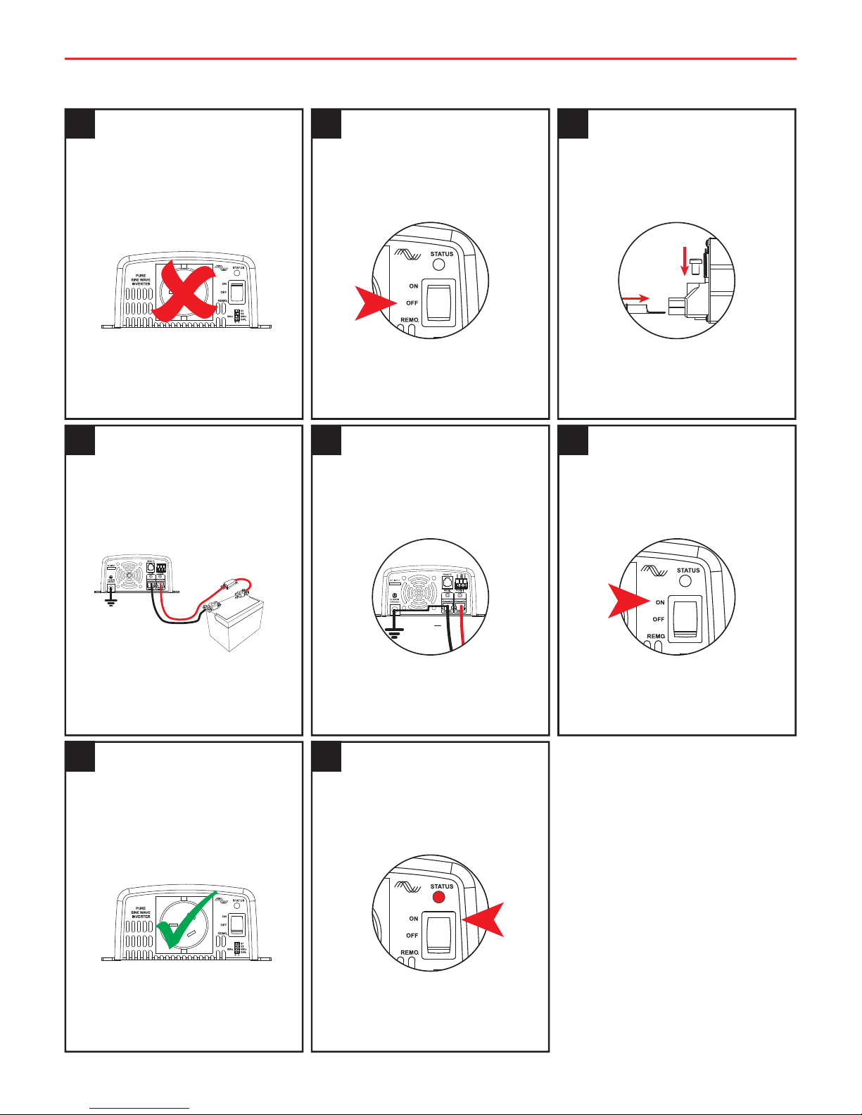
1.1 Quick Start Guide
Ensure all Loads
are Disconnected
1
Ensure no loads are
connected to the
Inverters AC Output.
Set Main Switch
to ‘OFF’
2
Ensure that the
Inverter Main Switch
is set to the ‘OFF’
position.
Ensure unit is
Grounded
5
Connect Chassis
Ground Terminal to
Negative Input
Terminal
+
Set Main Switch
to ‘ON’
6
Switch the Inverter
Main Switch to the
‘ON’ position.
Connect DC
Cables
3
Connect the DC cables
to the Inverters DC
Input Terminals.
Check cable and
fuse size
(Refer section 2.2.4)
4
Ensure that the cable
is of adequate size
and is protected by
the correct sized fuse.
Switch OFF and
connect AC loads
7
If the LED is ‘Green’
switch unit off &
connect loads to the
Inverter AC Output.
Refer to section
2.1.3
8
If the Inverter Status
LED is not ‘Green’
please refer to
section 2.1.3.
Page 6

5
1 INTRODUCTION
1.2 Specifications
R-12-350RS R-24-350RS
Output Voltage 200 / 220 / 230 / 240VAC ± 5%
Rated Power 350W
Max. Rated Input Current 44A 22A
Surge Power 700W
Waveform Pure Sine Wave (THD<3% @ VCD, linear load)
Frequency 50/60Hz ± 0.1%
Nominal Input Voltage 12VDC 24VDC
Input Voltage Range 10.0~15.5VDC 20.0~31.0VDC
Efficiency (at rated VDC full) 89% 90%
No Load Power Consumption
Power Saving mode <90mA <60mA
No load standby <0.9A <0.5A
Battery Low Shutdown 10V ± 0.25V 20V ± 0.5V
Battery Low Alarm 10.5V ± 0.25V 21V ± 0.5V
Battery Low Restart 12V ± 0.25V 24V ± 0.5V
Battery High Alarm 15V ± 0.25V 30V ± 0.5V
Battery High Shutdown 15.5V ± 0.25V 31V ± 0.5V
Battery High Restart 14.5V ± 0.25V 29V ± 0.5V
Protections Overload / Short Circuit / DC Over or Under Voltage / Over Temp.
Working Temperature -20°C~50°C (Derates to 60°C)
Storage Temperature -30°C~70°C
Working Humidity Max 90% RH non-condensing
Safety & EMC Certified EN 60950-1
Certified EN55022, EN 55024, EN 61204-3,
EN61000-3-2, -3-3, EN61000-6-1, -6-3,
IEC 61000-4-2, 3, 4, 5, 6, 8, 11
Dimensions 150x68x187 mm
Weight 1.6Kg
Cooling Load (53 ± 3%) and temperature (55 ± 5°C) control fan
Power Saving If set - Active after 25 seconds with load < 20W
Page 7

6
1 INTRODUCTION
1.3 Dimensions
150 [5.91]
68 [2.68]
35.7 [1.41] 116.0 [4.57]
22 [0.87]
127 [5.00]
187 [7.36]
Page 8

7
2 USER GUIDE
RISK OF ELECTRICAL SHOCK. DO NOT DISASSEMBLE THE INVERTER - THE INTERNAL
CIRCUITRY CONTAINS HAZARDOUS VOLTAGES. ATTEMPTING TO SERVICE THE UNIT
YOURSELF MAY RESULT IN ELECTRIC SHOCK OR FIRE AND WILL VOID THE UNIT WARRANTY.
2.1 Front Panel Operation
The R-12-350RS and R-24-350RS are members of the most advanced line of mobile AC power
systems available. To get the most out of the power inverter, it must be installed and used properly.
Please read the instructions in this manual before installation and operating.
2.1.1 Main Switch
The 3 stage switch is for turning ON or OFF and selecting Remote mode
Set the power switch to the “ON” position. The inverter will perform self-diagnosis and the LEDs
will display various colours.
Set the power switch to the “OFF” position. The inverter will stop and all LEDs will turn off.
2.1.2 Function Switch
Power saving, Output frequency and Output voltage settings can be controlled using the
dipswitches found on the AC output end of the inverter.
2.1.1.1 Output voltage
Output Voltage Switch 1 Switch 2
200VAC 0 0
220VAC 0 1
230VAC 1 0
240VAC 1 1
2.1.1.2 Output Frequency
Frequency (Hz) Switch 3
50Hz 0
60Hz 1
2.1.1.3 Power saving
Power Saving Mode Switch 4
On 1
Off 0
50Hz
S1
S2
60Hz
SAV
0 1
Default positions shown
Page 9

8
2 USER GUIDE
2.1.3 Indicator LED
Status LED Signal
Power On/Normal
Green
Saving Mode
(Shutdown after 30 mins)
Green Green Green
Output over load (100-115%)
(Shutdown after 30 seconds and
restart 4 times)
Red
Output Short Circuit
(Shutdown after 2 seconds and
restart 4 times)
Red
Over Temperature
Red Red Red Red
Shutdown High Battery
Red Red Red Red Red Red
High Battery
Orange Orange Orange Orange Orange Orange
Low Battery
(5 short beeps every 15 sec)
Orange Orange Orange
Shutdown Low Battery
Red Red Red
2.2 Rear panel operation
A
B
D
C
Page 10

9
2 USER GUIDE
2.2.1 Remote Port (RJ-11)
The RS Series inverter can be used with the REMOTE-RS remote controls. To enable use, the main
switch on the inverter must be set to the “REMOTE” position.
Pin Number Signal Description (1)
1 Reserved --
2 GND Same Polarity as Battery Negative
3 Reserved --
4 Reserved --
5 RMT Remote controller panel (positive)
6 Reserved --
2.2.2 Remote Control Green Terminal
Pin Number Terminal Description
1 GND
2 Enable- (ENB)
3 Enable+ (ENB)
• Before Installing - Make sure that the inverter main switch is at “OFF” position
• Before using the remote function, make sure the main switch is set to “REMOTE”
• Use 20-24AWG cable to connect the remote control terminals
2.2.3 Chassis Ground
Always connect chassis ground to battery negative. Use 1.5mm² or more.
RISK OF ELECTRICAL SHOCK. OPERATION OF THE INVERTER WITHOUT A PROPER GROUND
CONNECTION MAY RESULT IN AN ELECTRICAL SAFETY HAZARD. ENSURE PROPER GROUND
CONNECTION IS MADE DURING INSTALLATION. FOR FIXED AND/OR TRANSPORTABLE (VEHICLE) INSTALLATIONS, INSTALL ACCORDING TO APPROPRIATE AS/NZS STANDARD.
ABC
Page 11

10
2 USER GUIDE
2.2.4 DC Input Connection
Prior to installation:
• DC Supply cables should be as short as possible (no longer than the values in table 2.2.4.1)
• The size of the cable should be thick enough to maintain a voltage drop of less than 2%
when carrying the maximum input current. This will help prevent frequent low-input voltage
warnings and shutdown.
• The following sizes of cables and fuses are recommended for connection of the supply
batteries to inverter, see table 2.2.4.1 below for suitable cable sizing for your installation.
• Ensure lugs suitable to the selected cable size and to the inverter terminals are used, refer to
table 2.2.4.2 below for suitable lug size with reference to your chosen cable size.
Table 2.2.4.1 - Recommended Cable & Fuse Sizing
Cable Length
12V Models 24V Models
Cable Size mm² (AWG)
Inline Fuse Rating (A)
Midi
Cable Size mm² (AWG)
Inline Fuse Rating (A)
Midi
0 - 1m 13 (6) 50 6 (10) 30
1 - 2m 13 (6) 50 6 (10) 30
2 - 3m 21 (4) 50 8 (8) 30
3 - 4m 27 (3) 50 8 (8) 30
4 - 5m x x 13 (6) 30
5 - 6m x x 13 (6) 30
Fuse ratings are suitable to these recommended cable sizes.
2.3 Protection features
Model
DC Input (VDC)
Over Temperature
Protection
Over Voltage Under Voltage
Shut-down Restart
Shutdown Restart Alarm Shutdown Restart
R-12-350RS
15.5±0.25V 14.5±0.25V 10.5±0.25V 10.0±0.25V 12.0±0.25V
83±5°C 53±5°C
R-24-350RS
31.0±0.5V 29.0±0.5V 21.0±0.5V 20.0±0.5V 24.0±0.5V
Note: The specifications are subject to change without notice
D
Page 12

11
3 INSTALLATION
3.1 Mounting
The power inverter should be used in an environment that meets the following requirements:
1. Dry – Do not allow water to drip on or enter into the inverter.
2. Cool – Ambient air temperature should be between 0°C and 40°C, the cooler the better.
3. Safe – Do not install the inverter in a battery compartment or other areas where volatile
fumes may exist, such as fuel storage areas or engine compartments.
4. Ventilated – Keep the inverter at a distance (at least 25mm) away from surrounding
objects. Ensure the ventilation shafts on the rear and the bottom of the unit are not
obstructed.
5. Dust – Do not install the inverter in a dusty environment where the dust can be inhaled
into the unit when the cooling fan is working.
6. Fused – A fuse must be fitted between the battery and the Inverter.
7. Close to batteries – Avoid excessive cable lengths however the unit should not be installed
within 300mm or in the same compartment as a battery.
8. Use the recommended wire lengths and sizes (see section 2.2.4).
9. Do not mount the inverter where it will be exposed to the gasses produced by the battery.
These gasses are very corrosive, and prolonged exposure will damage the inverter.
RISK OF ELECTRICAL SHOCK. DO NOT EXPOSE THE INVERTER TO RAIN, SNOW, SPRAY, BILGE
OR DUST. DOING SO MAY RESULT IN DAMAGE TO THE INVERTER OR OTHER APPLIANCES
INSTALLED IN THE SYSTEM OR RESULT IN ELECTRIC SHOCK OR FIRE.
3.2 Ventilation Fan
The fan is load controlled and will engage when the AC Power Consumption reaches a certain level.
Ensure that the fan is not obstructed and is at a distance of at least 25mm from surrounding objects.
Install the inverter in a well-ventilated area with reasonable clearance. Do not install the
inverter in a zero-clearance compartment or obstruct the ventilation openings. Doing so
may result in the inverter overheating and ultimately damage the inverter.
Page 13

12
3 INSTALLATION
3.3 DC wiring connections
RISK OF ELECTRICAL SHOCK. BEFORE PROCEEDING, CAREFULLY CHECK THAT THE INVERTER
IS NOT CONNECTED TO ANY BATTERIES AND THAT ALL WIRING IS DISCONNECTED FROM
ANY ELECTRICAL SOURCES.
DO NOT CONNECT THE OUTPUT TERMINALS OF THE INVERTER TO AN INCOMING AC SOURCE.
DC supply cables should be kept as short as possible whilst still adhering to the above installation
requirements (ideally less than 1.8m / 6ft). Cables should be of an adequate size to handle the
required currents.
Cables which are not of adequate size (too thin) will result in Voltage drop and poor performance
of the inverter (such as poor surge capability, low-input voltage warnings and shutdowns). As
the supply cable increases in length or reduces in size (gets narrower) the voltage drop will
increase.
Batteries are capable of providing very large currents in the case of a short circuit. A fuse must
be installed on the positive supply cable as close as practical to the battery. Failure to do so
provides inadequate protection against fire in the case of a short circuit. Only use high quality
copper cable and keep the cable length short, refer to section 2.2.4 for more information.
Reverse polarity connection will blow the internal fuse and may cause permanent damage
to the inverter.
Before making the DC wiring connections, the main switch (page 7) must be set to “OFF”.
Connect the DC input terminals to an appropriate battery supply or other DC power source.
Power source [ + ] is positive and [ - ] is negative.
Battery
Fuse or
Circuit Breaker
+
Page 14

13
3 INSTALLATION
Ensure that all the DC connections are tight - torque to 2.8 Nm (1.5 ft-lbs). Loose
connections could result in overheating and can be a potential hazard.
Do not operate the inverter with damaged or substandard wiring. Selecting the wrong
cable or fuse size could result in harm to the installer or user and/or damage to the
inverter or other appliances installed in the system. The installer is responsible for
ensuring that the correct cable and fuse sizes are used when installing this inverter.
Refer to section 2.2.4 for more information.
3.4 AC Safety Grounding
Depending on the user scenario, the AC output of the inverter may require a user installed
breaker or fuse. The inverter incorporates AC short circuit protection.
RCDs may be fitted by a licenced electrician in installations using these inverters. These
inverters, when installed according to the instructions in this manual, are categorised as
EPB inverters. Neither active, nor neutral is referenced to ground and/or chassis within
the inverter. An RCD will not trip when used with this inverter unless a (MEN) neutral to
earth connection is implemented before the RCD. External connection of such should be
determined as appropriate or not by the licenced electrician.
The AC output ground wire should be connected to the grounding point of the connected loads (for
example, a distribution panel ground bus). If in doubt, consult a licensed electrician.
Residual Current Devices (RCD)
Certain installation codes and/or government regulations requiring the installation of an RCD must
be done by a licensed electrician.
3.5 Maintenance
Very little maintenance is required to keep the inverter operating correctly. The exterior of the
inverter should be cleaned periodically with a damp cloth to prevent accumulation of dust and dirt.
At the same time, tighten the screws on the DC input terminals. Turn the unit OFF before cleaning.
M5 Screw
Ring Terminal
Cable
Page 15

14
4 TWO YEAR PRODUCT WARRANTY
Over the last three decades our company has established a reputation as the power conversion specialist.
A 100% Australian-owned company, we have met the needs of customers in transport and other industries through exciting, innovative thinking.
We believe in total customer satisfaction and practice this by offering our customers:
• Technical advice free of jargon and free of charge
• Prompt turnaround of orders throughout Australia and globally
• Friendly, personalised, professional service and product support
In the unlikely event that a technical issue arises with a REDARC product, customers are encouraged to initially contact the REDARC Technical Support Team on (08) 8322
4848 or power@redarc.com.au for prompt and efficient diagnosis and product support.
Our goods come with guarantees that cannot be excluded under the Australian Consumer Law. You are entitled to a replacement or refund for a major failure and compensation for
any other reasonably foreseeable loss or damage. You are also entitled to have the goods repaired or replaced if the goods fail to be of acceptable quality and the failure does not
amount to a major failure.
The benefits of this Warranty are in addition to other rights and remedies available at law in respect of the Products and shall not derogate from any applicable mandatory statutory
provisions or rights under the Australian Consumer Law.
REDARC Electronics Pty Ltd atf the REDARC Trust trading as REDARC Electronics (“REDARC”) offers a warranty in respect of its Products where the Products are purchased from an
authorised distributor or reseller of REDARC by a person (“Purchaser”), on the terms and conditions, and for the duration, outlined below in this document (“Warranty”).
1. In this Warranty, the term Products means:
1.1 all products manufactured or supplied by REDARC (excluding its solar products
which are covered by REDARC’s Solar Product Warranty); and
1.2 any component of or accessory for any product in clause 1.1 manufactured or
supplied by REDARC.
Offer and duration of product warranties
2. REDARC warrants that its Products will be free, under normal application,
installation, use and service conditions, from defects in materials and workmanship
affecting normal use, for 2 years from the date of purchase (Warranty Period).
3. Where a Product malfunctions or becomes inoperative during the Warranty
Period, due to a defect in materials or workmanship, as determined by REDARC,
then subject to further rights conferred by the Australian Consumer Law on the
Purchaser, REDARC will, in exercise of its sole discretion, either:
3.1 repair the defective Product;
3.2 replace the defective Product; or
3.3 provide a refund to the Purchaser for the purchase price paid for the defective
Product,
without charge to the Purchaser.
4. The warranty given by REDARC in clause 3 covers the reasonable costs of delivery
and installation of any repaired or replaced Products or components of Products
to the Purchaser’s usual residential address notified to REDARC, together with the
reasonable costs of removal and return of any Products determined by REDARC to
be defective.
5. If the Purchaser incurs expenses of the nature referred to in clause 4 in the context
of making a claim pursuant to this Warranty that is accepted by REDARC, the
Purchaser will be entitled to claim for reimbursement of those expenses which
REDARC determines, in exercise of its sole discretion, to be reasonably incurred,
provided that the claim is notified to REDARC in writing at the postal address or
email address specified in clause 21 and includes:
5.1 details of the relevant expenses incurred by the Purchaser; and
5.2 proof of the relevant expenses having been incurred by the Purchaser.
Exclusions and limitations
6. This Warranty will not apply to, or include any defect, damage, fault, failure or
malfunction of a Product, which REDARC determines, in exercise of its sole
discretion, to be due to:
6.1 normal wear and tear or exposure to weather conditions over time;
6.2 accident, misuse, abuse, negligence, vandalism, alteration or modification;
6.3 non-observance of any of the instructions supplied by REDARC, including
instructions concerning installation, configuring, connecting, commissioning,
use or application of the Product, including without limitation choice of location;
6.4 failure to ensure proper maintenance of the Product strictly in accordance
with REDARC’s instructions or failure to ensure proper maintenance of any
associated appliances or machinery;
6.5 repairs to the Product that are not strictly in accordance with REDARC’s
instructions;
6.6 installation, repairs or maintenance of the Product by, or under the supervision
of, a person who is not a qualified auto electrician or technician, or if nongenuine or non-approved parts have been fitted;
6.7 faulty power supply, power failure, electrical spikes or surges, lightning, flood,
storm, hail, extreme heat, fire or other occurrence outside the control of
REDARC;
6.8 use other than for any reasonable purpose for which the Product was
manufactured;
6.9 any indirect or incidental damage of whatever nature outside the control of
REDARC.
7. Warranty claims in respect of a Product must be made in writing to REDARC at the
postal address or email address specified in clause 21 within the Warranty Period.
Such claims must include the following:
7.1 details of the alleged defect or fault and the circumstances surrounding the
defect or fault;
7.2 evidence of the claim, including photographs of the Product (where the subject
of the claim is capable of being photographed);
7.3 the serial number of the Product, specified on the label affixed to the Product;
and
7.4 proof of purchase documentation for the Product from an authorised distributor
or reseller of REDARC, which clearly shows the date and place of purchase.
The return of any Products without the prior written instructions of REDARC will not
be accepted by REDARC.
8. Without limiting any other clause in this Warranty, REDARC has the right to reject
any Warranty claim made by a Purchaser pursuant to this Warranty where:
8.1 the Purchaser does not notify REDARC in writing of a Warranty claim within the
Warranty Period;
8.2 the Purchaser does not notify REDARC in writing of a Warranty claim within
1 month of becoming aware of the relevant circumstances giving rise to the
claim, so that any further problems with the Product are minimised;
8.3 the serial number of the Product has been altered, removed or made illegible
without the written authority of REDARC;
8.4 the Purchaser is unable to provide proof of purchase documentation in
accordance with clause 7.4 or evidence that the Product was properly installed
and removed (if relevant), and that proper maintenance has been performed
on the Product, by, or under the supervision of, a qualified auto electrician or
technician, in accordance with the instructions of REDARC.
9. If the Product is found to be working satisfactorily on return to REDARC or upon
investigation by REDARC, the Purchaser must pay REDARC’s reasonable costs of
testing and investigating the Product in addition to shipping and transportation
charges. Where REDARC is in possession of the Product, the Product will be
returned to the Purchaser on receipt of the amount charged.
10. Any replaced Products or components of Products shall become the property of
REDARC.
11. REDARC may, in exercise of its sole discretion, deliver another type of Product
or component of a Product (different in size, colour, shape, weight, brand and/
or other specifications) in fulfilling its obligations under this Warranty, in the event
that REDARC has discontinued manufacturing or supplying the relevant Product or
component at the time of the Warranty claim, or where such Product or component
is superior to that originally purchased by the Purchaser.
Other conditions of Warranty
12. If the Purchaser acquired a Product for the purpose of resupply, then this Warranty
shall not apply to that Product.
13. In particular, the sale of a Product via an online auction, online store or other
internet website by a party that is not an authorised distributor or reseller of the
Product will be deemed to be a resupply within the meaning of the Australian
Consumer Law and will render this Warranty void, as REDARC has no control over
the storage, handling, quality or safety of Products sold by such persons.
14. A Purchaser shall only be entitled to the benefit of this Warranty after all amounts
owing in respect of the Product have been paid.
15. While REDARC warrants that the Products will be free from defects in materials and
workmanship in the circumstances set out in this Warranty, to the maximum extent
permitted by law REDARC does not warrant that the operation of the Products will
be uninterrupted or error-free.
16. To the maximum extent permitted by law, REDARC’s determination of the existence
of any defect and the cause of any defect will be conclusive.
17. Spare parts or materials for the Products are guaranteed to be available for a period
of at least 2 years after purchase of the Products.
18. The agents, officers and employees of any distributor or reseller of the Products and
of REDARC are not authorised to vary or extend the terms of this Warranty.
19. REDARC shall not be responsible or liable to the Customer or any third party in
connection with any non-performance or delay in performance of any terms and
conditions of this Warranty, due to acts of God, war, riots, strikes, warlike conditions,
plague or other epidemic, fire, flood, blizzard, hurricane, changes of public policies,
terrorism and other events which are beyond the control of REDARC. In such
circumstances, REDARC may suspend performance of this Warranty without liability
for the period of the delay reasonably attributable to such causes.
20. If a clause or part of a clause in this Warranty can be read in a way that makes it
illegal, unenforceable or invalid, but can also be read in a way that makes it legal,
enforceable and valid, it must be read in the latter way. If any clause or part of
a clause in this Warranty is illegal, unenforceable or invalid, that clause or part is
to be treated as removed from this Warranty, but the rest of this Warranty is not
affected.
REDARC’s contact details
21. REDARC’s contact details for the sending of Warranty claims under this Warranty
are:
REDARC Electronics Pty Ltd
23 Brodie Road (North), Lonsdale SA 5160
Email: power@redarc.com.au
Telephone: +61 8 8322 4848
Page 16

Free technical assistance!
please contact
REDARC Electronics
23 Brodie Road North, Lonsdale SA
(08) 8322 4848
power@redarc.com.au
www.redarc.com.au
Copyright © 2017 REDARC Electronics Pty Ltd. All rights reserved.
MADE IN CHINA
www.redarc.com.au
WAR350RSInverters-REV7
 Loading...