

RED Voyager 1, Voyager 1 Beat Xtractor Mission Manual


INTRODUCTION ........................................................
FRONT PANEL ...........................................................
REAR PANEL ...............................................................
EXT. MIDI SEQUENCER SETTINGS ................
OPERATING CRITERIA ...........................................
INPUT LEVEL SETTINGS ......................................
CONNECTIONS - OPTION A ..............................
CONNECTIONS - OPTION B ..............................
OPERATION
Getting started / Powering Up ........................
BPM Displays .............................................................
Selecting the Active Channel .............................
Controlling The MIDI Clock ..................................
Run/Pause ..................................................................
Beat One Re-Set .....................................................
Tap (Stop) .....................................................................
Cue ...................................................................................
Beat Tracking Indicator .........................................
Background Channel ..............................................
Switching Channels .................................................
10
11
11
12
13
14
14
16
18
18
19
2
3
5
6
6
7
8
9
TROUBLESHOOTING /HINTS & TIPS........
SPECIFICATION ......................................................
1
VOYAGER 1 - CONTENTS
20
21

INTRODUCTION
Thank you for buying the RED VOYAGER 1 Beat Xtractor.
essential, creative DJ re-mix product of the decade.
have purchased is
Described by DJ magazine's Daniel Duffel as 'The missing link between
audio and MIDI', the VOYAGER 1 analyses audio signals from vinyl or CD/
tape and calculates the tempo or 'BPM' of the tracks.
The BPM's are displayed but, more importantly, the beat information from
one of the channels is used to generate a MIDI Clock signal which runs in
synchronisation with the audio track enabling any connected MIDI
sequencer/tone module such as **Roland's MC303/ MC505, EMU's Orbit /
Planet Phatt, QuasiMidi's latest Rave-o-lution 309 or in fact any computer
/sequencer software setup to automatically lock-in and track the tempo of
the audio.
The VOYAGER 1's intelligent software constantly monitors and corrects the
relative audio / MIDI beat synchronisation to keep the beats locked together
and also follows any tempo changes in real-time if vinyl/CD deck pitch
controls are adjusted.
Now, for the first time, the tempo of patterns & songs programmed into your
MIDI sequencer can be controlled directly from the audio leaving you free
to add or 'tweak' your own MIDI music / percussion parts and produce the
ultimate, individual DJ performance.
Please read the following sections of this manual carefully to understand
the full potential of your VOYAGER 1 Beat Xtractor.
the
The product you
Ready for launch!
** Trademarks of E-MU Systems / Roland Corp. Japan / Quasimidi
RED
TM
VOYAGER 1
Beat Xtractor
VOYAGER 1 MISSION GUIDE
2
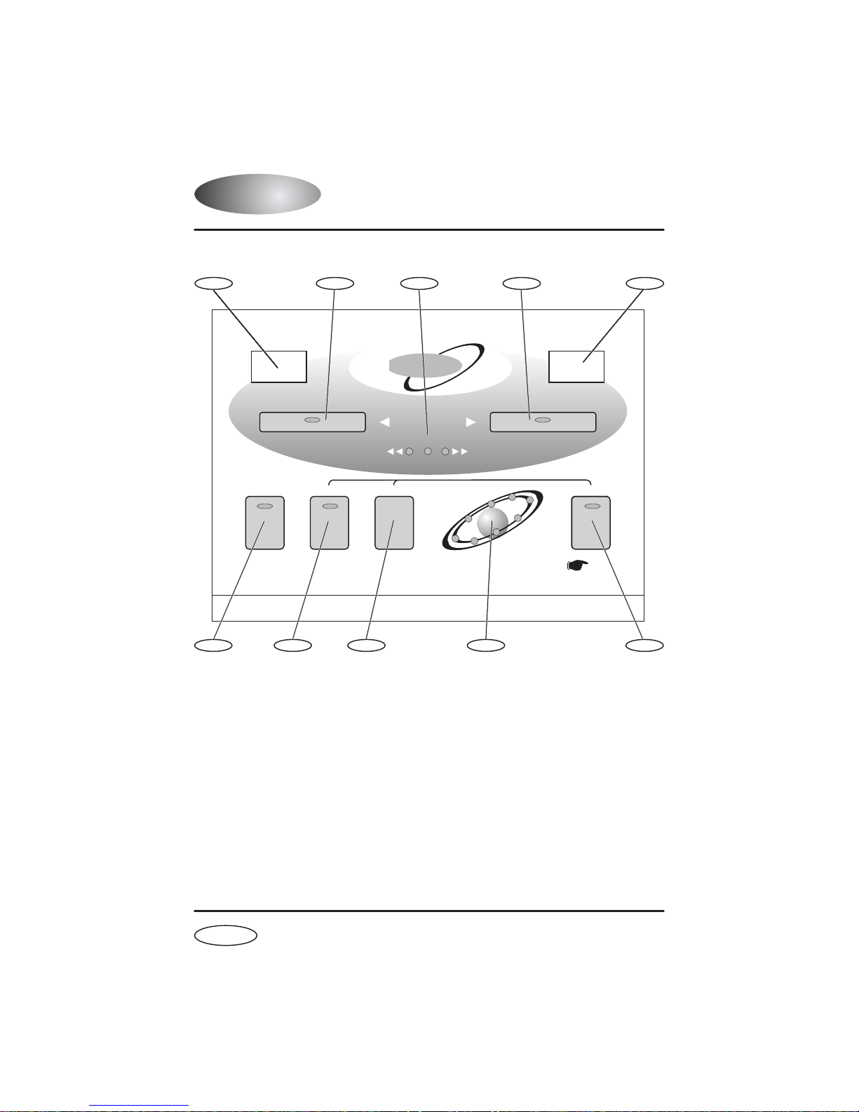
FRONT PANEL
1
www.redsound.com
CH 1 BPM
CHANNEL 1
6
1
CHANNEL 1 Display
7
2
CUERUN/PAUSE
RED
BEAT ONE
8
3
VOYAGER 1
Beat Xtractor
SELECT
OKPULL PUSH
BEAT TRACKING
+/ Up TempoEdit-/Down
RE-SET
CHANNEL 2
Beat One
MIDI CLOCK
9
4
CH 2 BPM
TAP
(STOP)
The BPM reading of the Channel 1 audio input will be displayed here.
5
10
2
CHANNEL 1 Button
Press this button to select Channel 1 as the active channel for driving the
MIDI Clock output. Also, press and hold to de-activate the beat tracking.
3
BEAT TRACKING Indicator
This 3-way indicator shows any internal synchronisation adjustments.
4
CHANNEL 2 Button
Press this button to select Channel 2 as the active channel for driving the
MIDI Clock output. Also, press and hold to de-activate the beat tracking.
3
VOYAGER 1 - FRONT PANEL

FRONT PANEL
5
CHANNEL 2 Display
The BPM reading of the Channel 2 audio input will be displayed here.
6
RUN/PAUSE Button
Press this button to Run and Pause your MIDI sequencer.
7
CUE Button
Press this button to set the 'Cue Paused' and 'Cue Ready' modes - see
page16 for further information.
8
BEAT ONE RE-SET Button
Press and release this button to re-align the start point (beat1/bar1) of the
current pattern or song in your MIDI sequencer with any chosen point in the
audio track.
9
MIDI CLOCK Display
This 8 indicator display 'rotates' at the detected BPM speed when the
VOYAGER 1 is in RUN mode (MIDI Clock running). As the display rotates,
the 'Beat One' indicator flashes brighter to show each beat of the bar. The
Beat One indicator also flashes at the detected BPM when the
VOYAGER 1 is in PAUSE mode.
10
TAP (STOP) Button
'Tap' this button to manually enter a tempo if there is no audio signal
present or when the regular patterns and beats in the audio track become
unavailable. When used in conjunction with the '- / Down' and '+/ Up'
buttons (Tempo Edit mode - LED on) the tempo can be set more accurately
in single BPM steps. The MIDI Clock will run at the set BPM.
Also, when this button is pressed and held for approx.1 second the MIDI
Clock will stop.
VOYAGER 1 MISSION GUIDE
4
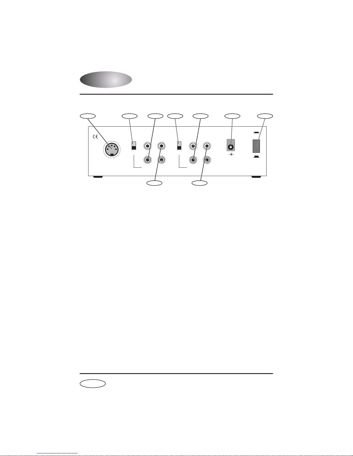
REAR PANEL
1 4 76
www.redsound.com
MIDI CLOCK
OUT
VOYAGER 1
Beat Xtractor
1
MIDI OUT Connector
23
CHANNEL 2
PHONO PHONO
L
CD/LINE CD/LINE
R
IN OUT
RED Sound Systems Ltd
89
5
CHANNEL 1
OUTIN
POWER
L
-
R
+
9v DC
REFER TO QUALIFIED SERVICE PERSONNEL
NO USER SERVICEABLE PARTSINSIDE
MADE IN ENGLAND
CAUTION: DO NOT OPEN CASE
ON
OFF
Use a suitable MIDI cable to connect the MIDI 'IN' of your MIDI sequencer
to this connector .
2
CHANNEL 2 Input select switch
This selects the Channel 2 input signal level.
NOTE:
The setting of this
switch must always match the input channel on your mixing desk. i.e if
'PHONO' input is selected on the VOYAGER 1 use a 'PHONO' level input
on your mixing desk. Nominal input levels - CD/Line 2.0V - Phono 5mV
3
CHANNEL 2 Input connectors
Connect the left (L) and right (R) output of the Channel 2 sound source
(CD, phono, tape etc.) to these connectors.
4
CHANNEL 1 Input select switch
This selects the Channel 1 input signal level -
5
CHANNEL 1 Input connectors
Connect the left (L) and right (R) output of the Channel 1 sound source
(or the mixing desks MASTER outputs (see Option B) to these connectors.
6
DC POWER IN connector
Only use the AC/DC adaptor supplied with this product - 'RED PSU'.
7
POWER switch
This turns the power on/off.
5
VOYAGER 1 - REAR PANEL
see NOTE at 2 above.

MIDI SETTINGS
8
CHANNEL 2 Output connectors
Connect the channel 2 audio outputs to a suitable mixing desk input.
9
CHANNEL 1 Output connectors
Connect the channel 1 audio outputs to a suitable mixing desk input.
EXTERNAL MIDI SEQUENCER SETTINGS
Before the VOYAGER 1 can operate correctly you must first ensure that
your MIDI sequencer is set to respond to MIDI Clock commands.
Please consult the manufacturers operation manual to make the necessary
settings. Here are some typical examples:
ROLAND MC-303
In System Settings, set the 'SYNCHRONIZATION SETTING' to 'Slave'
mode.
E-MU Orbit / Planet Phatt etc.
In Master Menu, set 'GLOBAL TEMPO' down below 1 BPM to 'External'
mode and set the 'BEATS MODE to 1, 2 or 3.
External
QUASIMIDI RAVE-O-LUTION 309
In the 'EDIT' page press F3 to select 'SYSTEM'. Select page 3 with the
'PAGE' dial. Use the 'EDIT VALUE' wheel to set MIDI SYNC to 'EXT'.
OPERATING CRITERIA
This product has been designed to operate most effectively with
dance music - i.e. music which is based on strong regular beats and
patterns. However, as the range of pre-recorded dance material is
virtually limitless (and the audio mix of individual tracks unknown) we
cannot guarantee the performance of the VOYAGER 1 with every
dance track.
The VOYAGER 1 may operate unsatisfactorily if the beat information
is either unavailable or indefinable within the audio track. Please note
this when selecting your audio source material.
VOYAGER 1 MISSION GUIDE
6
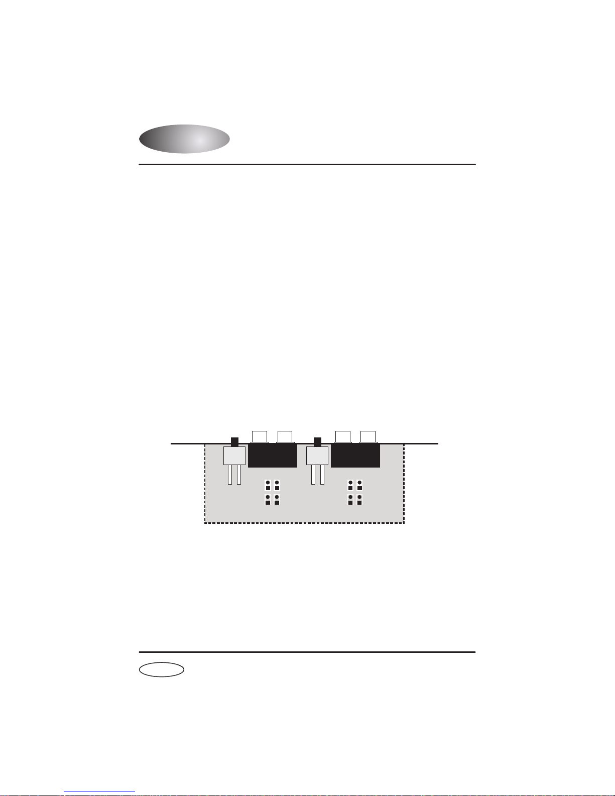
INPUT LEVELS
CD/LINE LEVEL SETTINGS
Selecting the correct input level is of the
VOYAGER 1. If the range setting is used you may experience
incorrect
problems with the VOYAGER 1's ability to detect the BPM (due to
critical to the performance
internal
low or overloaded signal levels).
The VOYAGER 1 is shipped with it's CD/Line levels preset for 'DJ' type
CD players. i.e. those which have a nominal output level of 2V 0dB.
If you wish to use the VOYAGER 1 with a Hi-Fi type CD player (or any
other player which has a nominal output level between 100 to 350mV) you
must first make changes to the jumper links for that channel within the
product.
1. Turn off the power and remove all the connectors from the back panel.
2. Turn the product over and remove the 4 screws holding the rear panel.
3. Lift off the rear panel and identify the 8 'jumper' links located on the
circuit card behind the rear panel connectors as detailed below.
CHANNEL 2 CHANNEL 1
J6
J5
DJ DJ
LOW LOW
J9
J10
CH 2
J11
J8
J7
J12
CH 1
'DJ' = 1V to 2.5V 'LOW' = 140mV to 350mV
5. To set Channel 1 to 'LOW ' level operation remove the two links J7, J8
and re-fit to J11, J12. To set Channel 2 to 'LOW ' level operation remove
the two links J5, J6 and re-fit to J9,J10. Press links firmly into position.
6. Check that no loose parts are left inside the product.
7. Replace the rear panel and refit the 4 screws.
7
VOYAGER 1 - INPUT LEVELS
 Loading...