

Page 1
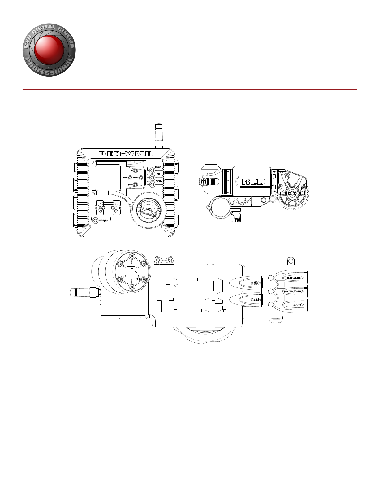
RED 3-AXIS LENS CONTROL SYSTEM
OPERATION GUIDE
W.M.D. | T.H.C. | Lens ConTroL MoTor
RED.COM
Page 2

RED 3-AXIS SYSTEM OPERATION GUIDE
TABLE OF CONTENTS
Disclaimer 3
Copyright Notice 3
Trademark Disclaimer 3
Compliance Statements 3
Safety Instructions 5
Battery Storage and Handling 6
Shipping Disclaimer 6
Chapter 1: 3-Axis System Overview 7
Introduction 7
3-Axis System Components 8
Additional Resources 9
Chapter 2: 3-Axis System Launch Sequence 10
Recommended Equipment 10
Prepare the Camera 11
Install the 3-Axis System 11
Connect the 3-Axis System 13
Configure the 3-Axis System 14
Configure Lens Control Motors 15
Metadata and Lens Profiles 15
Lens Limits and Lens Locks 15
Chapter 3: Wireless Motor Driver (W.M.D.) 16
W.M.D. Overview 16
W.M.D. Controls 17
W.M.D. LEDs 18
W.M.D. Connectors 19
Mount the W.M.D. 21
Power the W.M.D. 23
Connect Motors 23
Initialize with the W.M.D. 23
W.M.D. Main Menu 24
Configure Focus, Iris, and Zoom Motors 24
Configure Wireless Settings 26
View Motor Status 26
Configure Start/Stop, Genlock, TimeCode, Tally 27
W.M.D. Lens Profiles 28
Select a Lens Profile 29
Clear the Active Lens Profiles 29
Modify a Lens Profile 29
Save a Lens Profile 30
View Lens Metadata 30
Export Lens Profiles 30
Import Lens Profiles 30
Manage Lens Profiles 31
Access W.M.D. Diagnostic Data 31
Erase Settings on the W.M.D. 31
Chapter 4: Tactical Hand Controller (T.H.C.) 32
T.H.C. Overview 32
T.H.C. Controls 33
T.H.C. LEDs 34
T.H.C. Connectors 36
Wired Operation 37
Pair the T.H.C. 37
Change the Wireless Channel 38
Wireless Settings 38
Connect Two (2) T.H.C. Units 38
Initialize with the T.H.C. 38
Set a Lens Limit 39
Remove a Lens Limit 39
Set a Lens Lock 40
Remove a Lens Lock 40
Record Start/Stop with the T.H.C. 40
Chapter 5: Lens Control Motor 41
Lens Control Motor Overview 41
Lens Control Motor Mounting Bracket 42
19mm-to-15mm Rod Reducers 42
Lens Drive Gears 43
Install the Lens Control Motor 43
Connect the Lens Control Motor 44
Install a Lens Drive Gear 44
Remove a Lens Drive Gear 44
Chapter 6: System Maintenance 45
Clean 3-Axis System Components 45
Store the 3-Axis System 45
Chapter 7: Upgrade Firmware 46
MicroSD Card Preparation 46
Verify Current W.M.D. Firmware 46
Upgrade W.M.D. 46
Verify Current T.H.C. Firmware 47
Upgrade T.H.C. 47
Chapter 8: Troubleshoot the System 48
General Topics 48
Troubleshoot the W.M.D. 49
Troubleshoot Lens Control Motors 49
Troubleshoot Wireless Operations 50
Troubleshoot Firmware Upgrade 51
Appendix A: Technical Specifications 52
Tactical Hand Controller (T.H.C.) 52
Wireless Motor Driver (W.M.D.) 52
Lens Control Motor 53
RED Li Battery 7.2V 53
Appendix B: 3-Axis System Compatibility 54
Compatible Motors 54
Compatible Motor Drivers 54
Compatible Lenses 54
Appendix C: Connector and Cable Pinouts 55
W.M.D. Connectors 55
T.H.C. Connectors 60
Lens Control Motor Connectors 62
3-Axis System Cables 63
Appendix D: W.M.D. Main Menu Map 70
CoPYrIGHT © 2014 reD.CoM, InC
955-0044, reV-D | 2
Page 3
RED 3-AXIS SYSTEM OPERATION GUIDE
DISCLAIMER
RED has made every effort to provide clear and accurate information
in these installation instructions, which are provided solely for the
user’s information. While thought to be accurate, the information in
this document is provided strictly “as is” and RED will not be held
responsible for issues arising from typographical errors or user’s
interpretation of the language used herein that is different from that
intended by RED. All safety and general information is subject to
change as a result of changes in local, federal or other applicable
laws.
RED reserves the right to revise this document and make changes
from time to time in the content hereof without obligation to notify
any person of such revisions or changes. In no event shall RED, its
employees or authorized agents be liable to you for any damages
or losses, direct or indirect, arising from the use of any technical or
operational information contained in this document.
For comments or questions about content in this Operation Guide,
please send a detailed e-mail to OpsGuides@red.com.
COMPLIANCE STATEMENTS
INDUSTRIAL CANADA EMISSION COMPLIANCE STATEMENTS
This device complies with Industry Canada license-exempt RSS
standards RSS 139 and RSS 210. Operation is subject to the following two conditions: (1) this device may not cause interference, and
(2) this device must accept any interference, including interference
that may cause undesired operation of the device.
This Class B digital apparatus complies with Canadian ICES-003.
Le présent appareil est conforme aux CNR d’Industrie Canada ap-
plicables aux appareils radio exempts de licence. L’exploitation est
autorisée aux deux conditions suivantes : (1) l’appareil ne doit pas
produire de brouillage, et (2) l’utilisateur de l’appareil doit accepter
tout brouillage radioélectrique subi, même si le brouillage est susceptible d’en compromettre le fonctionnement.Cet appareil numérique de la classe B est conforme à la norme NMB-003 du Canada.
FEDERAL COMMUNICATIONS COMMISSION (FCC) STATEMENTS
This equipment has been tested and found to
comply with the limits for a Class B digital device, pursuant to part 15 of the FCC Rules.
These limits are designed to provide reasonable protection against harmful interference
in a residential installation. This equipment
generates, uses and can radiate radio fre-
quency energy and, if not installed and used
in accordance with the instructions, may cause harmful interference
to radio communications. However, there is no guarantee that interference will not occur in a particular installation. If this equipment
does cause harmful interference to radio or television reception,
which can be determined by turning the equipment off and on, the
user is encouraged to try to correct the interference by one or more
of the following measures:
Reorient or relocate the receiving antenna.
Increase the separation between the equipment and receiver.
Connect the equipment into an outlet on a circuit different from
that to which the receiver is connected.
Consult the dealer or an experienced radio/TV technician for
help.
In order to maintain compliance with FCC regulations, shielded
cables must be used with this equipment. Operation with non-approved equipment or unshielded cables is likely to result in interference to radio and TV reception. The user is cautioned that changes
and modifications made to the equipment without approval of manufacturer could void the users authority to operate this equipment.
COPYRIGHT NOTICE
COPYRIGHT© 2014 RED.COM, INC.
All trademarks, trade names, logos, icons, images, written material,
code, and product names used in association with the accompanying product are the copyrights, trademarks or other intellectual
property owned and controlled exclusively by RED.COM, INC.
TRADEMARK DISCLAIMER
All other company, brand, and product names are trademarks or
registered trademarks of their respective holders. RED has no affiliation to, is not associated or sponsored with, and has no express
rights in third-party trademarks. SD and microSD are registered
trademark of SD-3C, LLC in the United States, other countries or
both.
NOTE: This device complies with Part 15 of the FCC Rules.
Operation is subjected to the following two conditions (1) this device
may not cause harmful interference, and (2) this device must accept
any interference received, including that may cause undesirable interference.
CAUTION: Exposure to Radio Frequency Radiation.
The device shall be used in such a manner that the potential for human contact is minimized
This equipment complies with FCC radiation exposure limits set
forth for an uncontrolled environment. This equipment should be
installed and operated with a minimum distance of 20 cm between
the radiator and your body.
CAUTION: Regulations of the FCC and FAA
prohibit airborne operation of radio-frequency
wireless devices because their signals could
interfere with critical aircraft instruments.
CAUTION: If the device is changed or modified
without permission from RED, the user may
void his or her authority to operate the equipment.
AUSTRALIA AND NEW ZEALAND STATEMENTS
RED declares that the radio equipment described in this document
comply with the following international standards.
IEC 60065 - Product Safety
ETSI EN 300 328 - Technical requirement for radio equipment
RED declares digital devices described in this document comply
with the following Australian and New Zealand standards.
AS/NZS CISPR 22 – Electromagnetic Interference
AS/NZS 61000.3.2 – Power Line Harmonics
AS/NZS 61000.3.3 – Power Line Flicker
CoPYrIGHT © 2014 reD.CoM, InC 955-0044, reV-D | 3
Page 4
RED 3-AXIS SYSTEM OPERATION GUIDE
JAPAN STATEMENTS
This is a Class B product based on the
standard of the Voluntary Control Council
for Interference (VCCI) for information technology equipment. If this equipment is used
near a radio or television receiver in a domestic environment, it may cause radio interference. Install and use the equipment
according to the instruction manual.
EUROPEAN UNION COMPLIANCE STATEMENTS
RED declares that the radio
equipment described in this
document complies with the
R&TTE Directive (1999/5/
EC) issued by the Commission of the European Community.
Compliance with this directive implies conformity to the following
European Norms (in brackets are the equivalent international standards).
EN 60065 (IEC 60065) – Product Safety
ETSI EN 300 328 Technical requirement for radio equipment
ETSI EN 301 489 General EMC requirements for radio equip-
ment.
INFORMATION
Products with the CE marking comply with the EMC Directive
(2004/108/EC) and the Low Voltage Directive (2006/95/EC) issued
by the Commission of the European Community. Compliance with
these directives implies conformity to the following European Product Family Standards.
EN 55022 (CISPR 22) – Electromagnetic Interference
EN 55024-1 (CISPR 24) – Electromagnetic Immunity
EN 61000-3-2 (IEC610000-3-2) – Power Line Harmonics
EN 61000-3-3 (IEC610000) – Power Line Flicker
EN 60065 (IEC60065) – Product Safety
your nearest designated collection point. Penalties may be applicable for incorrect disposal of this waste, in accordance with you
national legislation.
For business users in the European Union, if you wish to discard
electrical and electronic equipment, please contact your dealer or
supplier for further information.
USAGE RESTRICTIONS FOR PRODUCTS THAT INCORPORATE
REDLINK
Products that fall into this category are denoted
by inclusion of the Class 2 identifier symbol (exclamation mark in a circle) accompanying the CE
Mark on the products regulatory label, example to
the left.
FRANCE
Usage Restrictions - Geographic Area Where Restriction Applies :
France
For mainland France
2.400 - 2.4835 GHz (Channels 1-16) authorized for indoor use
2.400 - 2.454 GHz (Channels 1-10) authorized for outdoor use
Restrictions d’utilisation - Zone géographique où les restrictions
s’appliquent : France
Pour la France métropolitaine
2.400 - 2.4835 GHz (Canaux 1 à 16) autorisé en usage intérieur
2.400 - 2.454 GHz (canaux 1 à 10) autorisé en usage extérieur
NORWAY
This subsection does not apply for the geographical area within a
radius of 20 km from the centre of Ny-Ålesund
Dette gjelder ikke for det geografiske området innenfor en radius av
20 km fra sentrum av Ny-Ålesund
RESPONSIBLE PARTY:
RED Digital Cinema
34 Parker
Irvine, CA 92618
USA
WASTE ELECTRICAL AND ELECTRONIC EQUIPMENT (WEEE)
The Waste Electrical and Electronic Equip-
ment (WEEE) mark applies only to countries
within the European Union (EU) and Norway.
This symbol on the product and accompanying documents means that used electrical
and electronic products should not be mixed
with general household waste. For proper
treatment, recovery and recycling, please
take this product to designated collection
points where it will be accepted free of
charge. Alternatively, in some countries you
may be able to return your products to your
local retailer upon purchase of an equivalent
new product.
Disposing of this product correctly will help save valuable resources
and prevent any potential negative effects on human health and the
environment, which could otherwise arise from inappropriate waste
handling. Please contact your local authority for further details of
CoPYrIGHT © 2014 reD.CoM, InC
955-0044, reV-D | 4
Page 5
RED 3-AXIS SYSTEM OPERATION GUIDE
SAFETY INSTRUCTIONS
DO NOT use the system or accessories near water. Avoid ex-
posing your system to moisture. The system is not waterproof,
so contact with water could cause permanent damage to the
system as well as electric shock and serious injury to the user.
DO NOT use the system in the rain or under other conditions
with high moisture without appropriate protection, and immediately remove power source if system or accessories are exposed to moisture.
WARNING: To reduce the risk of fire or electric shock, do not expose the camera or
system to rain or moisture.
DO NOT expose your system to excessive vibration or impact
(shock). Be careful not to drop your camera or system. Internal
mechanisms may be damaged by severe shock. Mechanical
alignment of optical elements may be affected by excessive
vibration.
ELECTROMAGNETIC INTERFERENCE: The use of devices us-
ing radio or other communication waves may result in the malfunction or interference with the unit and/or with audio and
video signals.
Clean only using a dry cloth. When cleaning your system, re-
member that it is not waterproof and moisture can damage
electronic circuitry. DO NOT rinse or immerse any element of
the camera, lens or other accessory, keep them dry at all times.
DO NOT use soaps, detergents, ammonia, alkaline cleaners,
and abrasive cleaning compounds or solvents. These substances may damage lens coatings and electronic circuitry.
Maintain sufficient ventilation - DO NOT block any ventilation
openings or obstruct cooling fan airflow.
CAUTION: Proper camera ventilation requires a minimum 1/2" (1.25 cm) clearance between the camera ventilation
openings and external surfaces. Verify
that objects that can block the fan intake
and exhaust ports do not impede airflow.
Failure to permit adequate airflow may result in overheating of the camera, degraded operation and in extreme situations,
damage to the camera.
en over by a vehicle. Replace any power cords suspected of
sustaining damage due to crushing or other forms of damage.
Lithium Ion batteries may be subject to special handling re-
quirements pursuant to federal and local laws. Please refer to
specific shipping instructions included with your battery regarding proper transport of your battery. Do not handle your
battery if it is damaged or leaking. Disposal of batteries must
be in accordance with local environmental regulations. For example, California law requires that all rechargeable batteries
must be recycled by an authorized recycle center. Storing batteries that are fully charged, fully discharged, in high temperatures, or otherwise outside the recommended storage conditions may permanently reduce the life of the battery. Available
battery capacity may also be temporarily lessened after storage in low temperature conditions.
WARNING: DO NOT expose batteries to excessive heat.
WARNING: Danger of explosion if an incorrect battery is charged with a RED Li
Battery Charger 7.2V or is used to power
the T.H.C. Replace only with the same or
equivalent type battery.
CAUTION: Refer all service and repair to
qualified RED service personnel. To reduce
the risk of electric shock, and damage to
the camera or accessories, DO NOT attempt to perform any servicing other than
any procedures that are recommended in
the operating instructions.
DO NOT operate or store near any heat sources such as radia-
tors, heat registers, stoves, or any other apparatus that produce heat. Store in a protected, level and ventilated place.
Avoid exposure to temperature extremes, damp, severe vibration, strong magnetic fields, direct sunlight or local heat sources during storage. Remove any batteries from the T.H.C. before
storage. Recommended storage and usage temperatures for
your system are:
‒ Operating range: 0°C to 40°C (32°F to 104°F)
‒ Storage range: -20°C to 50°C (-4°F to 122°F)
If there are any performance issues with your system when
operating within this temperature range, please file a support
ticket on support.red.com.
The W.M.D. is NOT HOT SWAPPABLE – meaning you cannot
remove or install while the camera is powered on. Before installing or removing, you MUST power down the camera. Failure to do so may result in damage to the accessory and / or
camera brain that will not be covered under warranty.
Protect all power cords from being pinched, walked on or driv-
CoPYrIGHT © 2014 reD.CoM, InC 955-0044, reV-D | 5
Page 6
RED 3-AXIS SYSTEM OPERATION GUIDE
BATTERY STORAGE AND HANDLING
WARNING: Failure to read, understand, and
follow these instructions may result in overheating, chemical leakage, smoke emission,
fire, or other potentially harmful results.
Always follow proper battery handling and storage practices. Improper handling and/or failure to abide by proper storage instructions may cause permanent damage to batteries, or degrade charge
capacity. Improper handling practices or failure to comply with instructions may also put you at risk.
LONG TERM STORAGE AND HANDLING
Lithium-Ion batteries, like the RED Li Battery 7.2V, REDVOLT®, REDVOLT XL, and RED BRICK®, self-discharge over time. When storing
for long periods of time, store batteries separately from the camera
or charger and remember to charge batteries to a capacity level of
50% to 80%. If batteries will be stored for long periods of time, RED
recommends that you check the charge level at least once every
six (6) months, and recharge batteries to a capacity level of 50%
to 80%.
When not in use, remove the battery from the camera or charger
and store the battery in a cool, dry place. Avoid non-insulated storage areas with fluctuating temperatures, extreme hot temperatures
(such as inside a hot car), corrosive gas, and direct sunlight. The
optimal storage temperature for batteries is between -20°C to 20°C
(-4°F to 68°F).
BATTERY CAUTIONS AND WARNINGS
WARNING: Batteries stored for a prolonged
period of time at less than 50% charge level
may permanently lose the ability to hold a
charge.
permanent damage.
DO NOT connect the positive (+) and negative (-) terminals to
a metal object such as a wire.
DO NOT allow batteries to get wet.
DO NOT transport or store batteries together with metal ob-
jects such as jewelry, hairpins, etc. as they may generate heat
if they come into contact with the battery.
DO NOT pierce batteries with pointed or other sharp objects.
DO NOT step on, throw, or strike batteries with a hammer.
DO NOT use batteries that appear to be deformed or damaged.
DO NOT put batteries into pressurized containers or micro-
wave ovens.
DO NOT use or subject batteries to intense sunlight or hot
temperatures such as a vehicle on a hot day.
Battery incorporates built-in safety devices. DO NOT use it in a
location where static electricity may be present.
DO NOT exceed the recharging temperature range of 0˚C to
40˚C (32˚F to 104˚F).
Only use RED chargers to recharge RED batteries.
If a battery leaks or gives off a bad odor, discontinue use im-
mediately.
If a battery gives off an odor, generates heat, becomes discol-
ored or deformed, or in any way appears abnormal during use,
recharging or storage, immediately remove it from the equip-
ment or battery charger and discontinue use.
If electrolyte from batteries comes into contact with skin or
clothing, immediately wash the area with running water. Failure
to do this may result in skin inflammation.
If electrolyte reaches the eyes, DO NOT rub them. Instead,
rinse the eyes with clean running water and immediately seek
medical attention. Failure to do this may result in eye injury.
If you find discoloration, a bad odor due to leakage, overheat-
ing and/or other irregularities when using a battery for the first
time, contact your Bomb Squad representative immediately.
WARNING: DO NOT use the battery for pur-
poses other than those specified.
WARNING: If recharging operation fails to
complete even after the specified recharging
time has elapsed, immediately stop further recharging.
Store batteries out of the reach of children.
DO NOT store batteries in a fully charged or discharged state
for extended periods of time.
DO NOT store batteries in a camera, camera module, or char-
ger for extended periods of time.
DO NOT store batteries in extreme hot or cold temperatures.
DO NOT expose batteries to fire or excessive heat.
DO NOT store batteries in direct sunlight.
DO NOT store, use, or recharge batteries near a heat source
such as a fire or a heater.
DO NOT use third-party chargers with your RED batteries.
DO NOT disassemble or modify batteries.
DO NOT overcharge batteries. Overcharging may increase in-
ternal temperature beyond the recommended limits and cause
CoPYrIGHT © 2014 reD.CoM, InC
NOTE: For more information regarding RED
battery charging and instructions for care,
please refer to our Terms and Conditions.
SHIPPING DISCLAIMER
Unless you have been certified to ship dangerous goods, you must
work with a Dangerous Goods, Class 9-certified shipper to assist
you with a shipment that includes a RED BRICK (or other regulated
lithium ion batteries). Please note that applicable laws prohibit the
shipping of batteries that are physically damaged. We urge you to
look into the formal rules and regulations of shipping Class 9 Dangerous Goods prior to preparing your shipment. For more information on these regulations, please visit www.iata.org and www.dot.
gov.
955-0044, reV-D | 6
Page 7
RED 3-AXIS SYSTEM OPERATION GUIDE
3-AXIS SYSTEM
01
01
INTRODUCTION
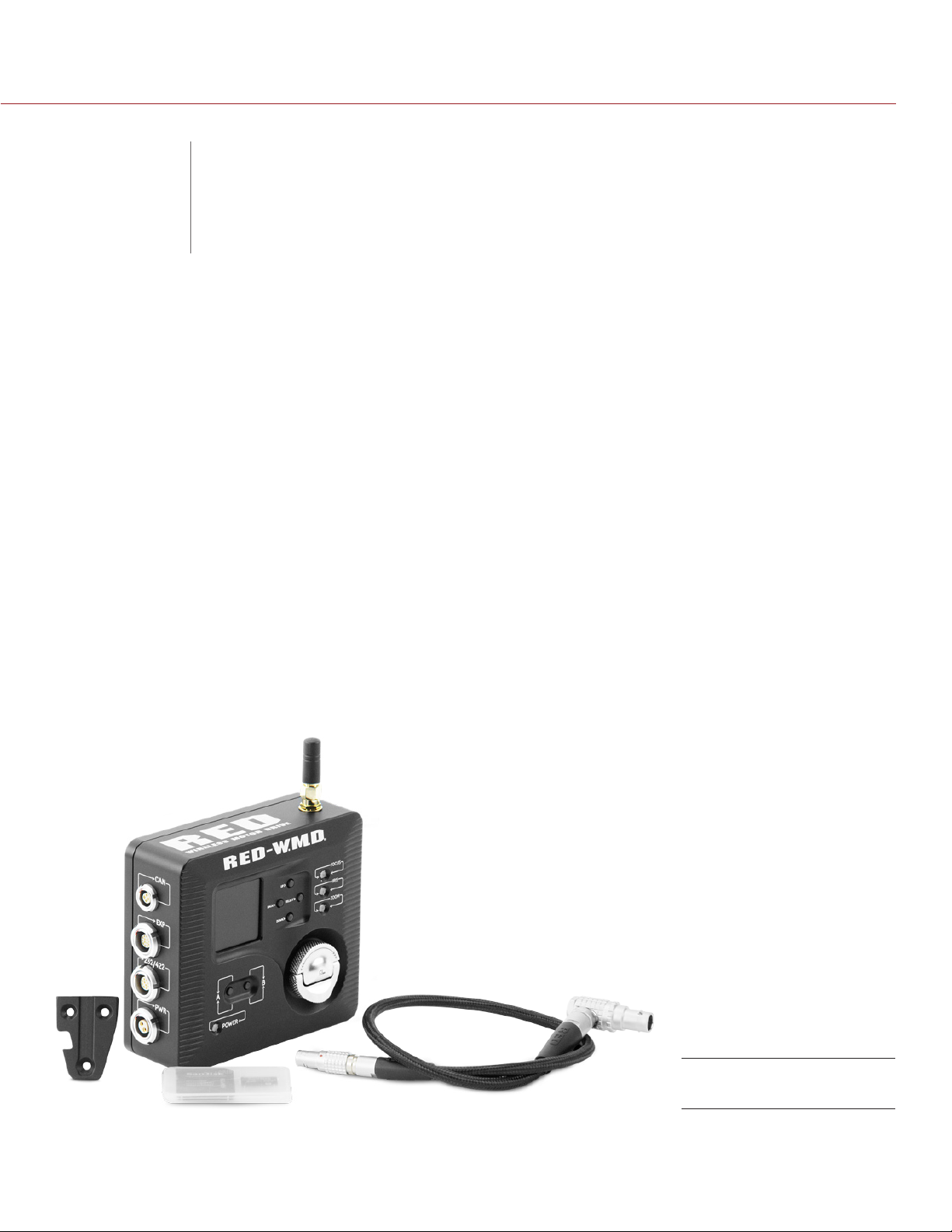
The RED 3-Axis Lens Control System is a versatile and highly accurate wireless lens control system. Use the
RED® Lens Control Motor, RED® Tactical Hand Controller (T.H.C.), RED® Wireless Motor Driver (W.M.D.), and
related RED accessories to configure a low-profile lens control system for your camera rig. This guide provides
setup and operation instructions for the RED Lens Control Motor, T.H.C., W.M.D., and related accessories.
The Tactical Hand Controller is also compatible with the REDLINK™ Bridge for wireless control of supported
Canon® and Nikon® motorized lenses. For more information, see the REDLINK Bridge Operation Guide, available
at www.red.com/downloads.
WARNING: ALWAYS use the RED motor cable with the appropriate internal identification resistor when using
RED LENS CONTROL MOTORs with third-party motor drivers. Any damage caused to motors or motor drivers
resulting from the use of third-party cables will not be covered under warranty.
NOTE: The DSMC does not require a minimum firmware version for operation with the W.M.D., T.H.C.,
Lens Control Motor, and other components of the RED 3-Axis Lens Control System.
OVERVIEW
COPYRIGHT © 2014 RED.COM, INC
955-0044, REV-D | 7
Page 8

RED 3-AXIS SYSTEM OPERATION GUIDE
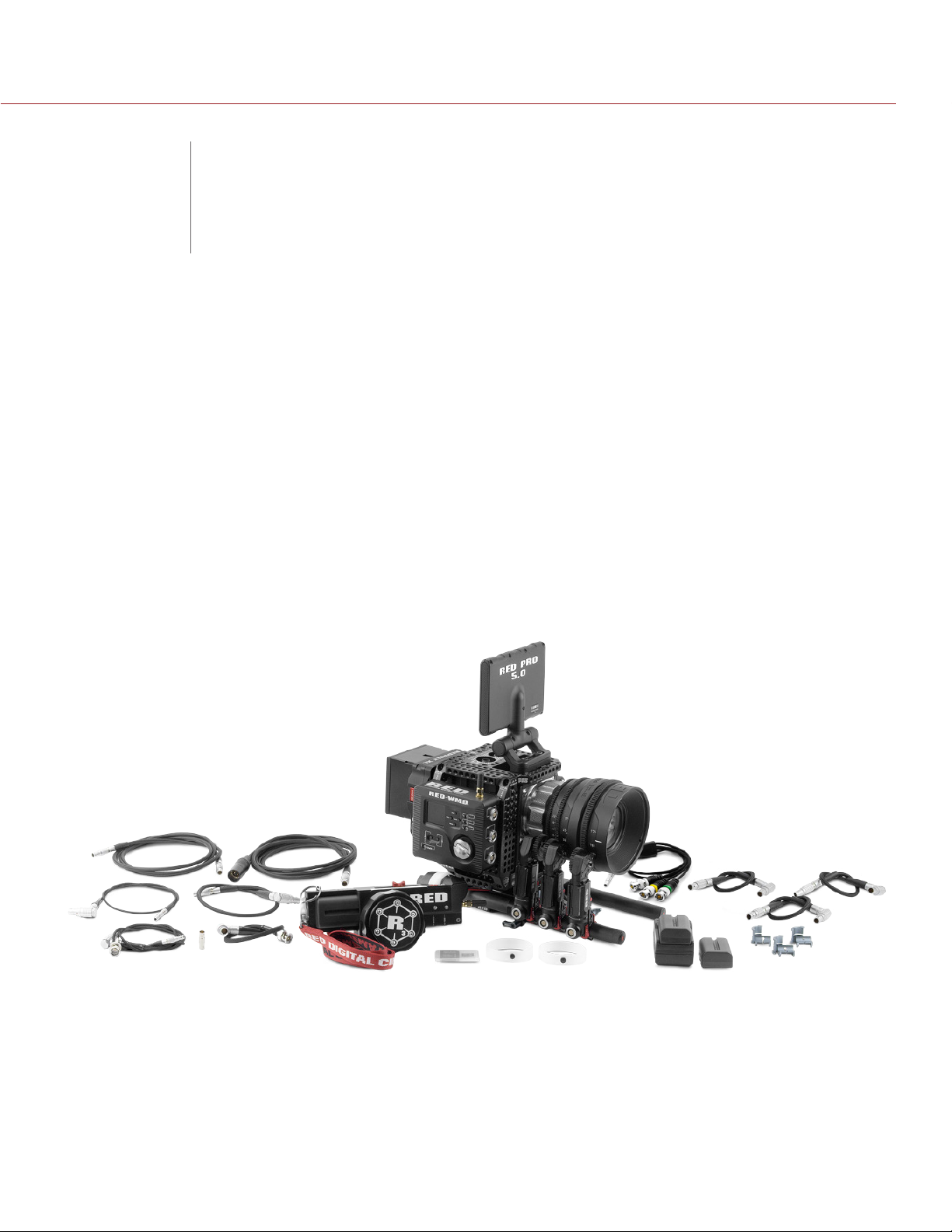
3-AXIS SYSTEM COMPONENTS
RED offers the following RED 3-Axis Lens Control System components individually, enabling you to customize
your lens control setup. For more information, visit the RED Store at www.red.com/store.
ITEM PART NUMBER
RED® 3-Axis Lens Control System 760-0147
RED® W.M.D. (Wireless Motor Driver) 790-0414
RED® T.H.C. (Tactical Hand Controller) 790-0413
RED® Lens Control Motor 760-0146
RED® Lens Drive Gear M 0.8 760-0139
RED® Lens Drive Gear M 0.6 760-0140
RED® Lens Drive Gear M 0.5 760-0141
RED® Lens Drive Gear M 0.4 760-0142
19mm-to-15mm Rod Reducer Kit 760-0151
RED® Lens Control Motor Mounting Bracket (Standard) 760-0137
RED® W.M.D. Motor Cable 7-Pin Straight to 7-Pin Right (12") 790-0434
RED® W.M.D. Motor Cable 7-Pin Straight to 7-Pin Right (18") 790-0406
RED® W.M.D. Motor Cable 7-Pin Straight to 7-Pin Right (24") 790-0412
RED® Lens Motor Cable (3.3KΩ version) 18" 790-0439
RED® Lens Motor Cable (3.3KΩ version) 24" 790-0438
RED® W.M.D. Power Cable 2-Pin 1B to 2-Pin 0B (18") 790-0410
RED® W.M.D. Power Cable 2-Pin 1B to 4-Pin XLR (8') 790-0411
RED® CAN Command Cable (5') 790-0407
RED® CAN Command Cable (50') 790-0408
RED® CAN Command Cable (100') 790-0409
REDLINK™-to-T.H.C. Connector Cable (3') 790-0444
RED® Start/Stop Cable (1B to Sync, Ctrl, BNC) 790-0415
RED® Start/Stop Cable (1B to BNC) 790-0416
RED® Start/Stop Cable (1B to 00B Sync) 790-0428
3BNC-to-00 Lemo Sync Cable 790-0154
Accessory Mount (V-Lock) 790-0370
RED® T.H.C./W.M.D. Antenna 790-0420
T.H.C. Focus Marking Ring 790-0430
Lanyard, RED Digital Cinema 010-0119
RED® Li Battery 7.2V 740-0032
RED® Li Battery Charger 7.2V 740-0033
3-Axis Systems Storage Case 790-0421
BNC-TO-BNC Adaptor 790-0435
COPYRIGHT © 2014 RED.COM, INC
955-0044, REV-D | 8
Page 9

RED 3-AXIS SYSTEM OPERATION GUIDE
ADDITIONAL RESOURCES
The following resources offer additional information about RED, the DSMC® system, and the RED community:
RED.com: Check the official RED website for latest information about RED products.
RED Learn Articles: RED offers in-depth technical articles about RED cameras, post-production, and digital
cinematography.
RED.com/downloads: Go to the RED Downloads page to download the latest firmware, operation guides,
and post-production software.
Support.red.com: Check the RED SUPPORT site for FAQs, or to file a support ticket.
REDUser.net: Discuss all things RED on the REDUSER third-party forum.
COPYRIGHT © 2014 RED.COM, INC 955-0044, REV-D | 9
Page 10

RED 3-AXIS SYSTEM OPERATION GUIDE
3-AXIS SYSTEM
02
This section offers condensed installation and operating instructions to help you get started using the
RED 3-Axis Lens Control System. For more detailed information on specific components, please refer to the
respective chapter in this guide.
WARNING: The DSMC® BRAIN® must be powered off during any installation process.
LAUNCH SEQUENCE
RECOMMENDED EQUIPMENT
The following RED products are suggestions for use, or are used to depict operations within this section:
12 - 18 V DC power source
‒ AC Power Adaptor (DSMC) with REDVOLT® XL Module
‒ RED Quickplate (Short) Module with attached RED BRICK
‒ Backpack Quickplate (Short) with attached RED BRICK
Mounting platform
‒ DSMC Tactical Cage
‒ DSMC Tactical Right Plate
Mounting system
‒ DSMC Modular Assault Plate Pack
‒ Quick Release Platform or Quick Release Platform (Mini)
15mm or 19mm support rods
‒ RED CARBON-X Rod (Carbon Fiber)
‒ Black Rod (Aluminum)
‒ Steel Rod (Steel)
NOTE: For more information and other compatible products, visit the RED Store at www.red.com/store.
®
COPYRIGHT © 2014 RED.COM, INC
955-0044, REV-D | 10
Page 11
RED 3-AXIS SYSTEM OPERATION GUIDE
PREPARE THE CAMERA
1. Install a mounting platform for the W.M.D. (Example: DSMC Tactical Cage or Tactical Right Plate)
2. Install a support rod system. (Example: DSMC Modular Assault Plate or Quick Release Platform)
3. Install 15mm or 19mm support rods.
INSTALL THE 3-AXIS SYSTEM
These instructions provide installation steps using a tactical cage or other cheeseplate. For more information
and other installation methods, go to “Mount the W.M.D.” on page 21.
1. Mount the W.M.D.
A. Remove the guide pin from the recessed storage location on the bottom of the unit.
B. Insert the guide pin into the bottom right mounting hole on the back of the W.M.D. for 18 mm mounting
configurations. Use the left mounting hole for 25 mm configurations.
Install the W.M.D. Guide
Pin
C. Position the W.M.D. at the desired location on the mounting platform, using the guide pin for alignment.
NOTE: Ensure you leave enough clearance on the sides to connect cables.
D. Push in and turn the 1/4-20 captive thumbscrew to initiate threading.
Mount the W.M.D.
COPYRIGHT © 2014 RED.COM, INC 955-0044, REV-D | 11
Page 12

RED 3-AXIS SYSTEM OPERATION GUIDE
E. Tighten the thumbscrew until hand tight.
WARNING: DO NOT OVERTIGHTEN.
2. Install the RED Lens Control Motor Mounting Bracket.
A. Push the lock button on the Lens Control Motor Mounting Bracket to disengage the locking mechanism.
B. Slide the dove-tail rail on the Lens Control Motor Mounting Bracket into the dove-tail slot on the
Lens Control Motor.
C. Release the lock button.
D. Tighten the M4 thumbscrew on the side of the Lens Control Motor Mounting Bracket to lock the bracket
in place.
3. Mount the Lens Control Motors to the support rods.
A. If you are using 15mm support rods, install the 19mm-to-15mm Reducer Bushings into the clamp.
B. Position the Lens Control Motors at the desired position on the support rods.
C. Use the thumbscrew to tighten the clamp on the Lens Control Motor Mounting Bracket.
NOTE: For more information, go to “Lens Control Motor” on page 41.
Mount
Lens Control Motors
COPYRIGHT © 2014 RED.COM, INC
955-0044, REV-D | 12
Page 13
RED 3-AXIS SYSTEM OPERATION GUIDE
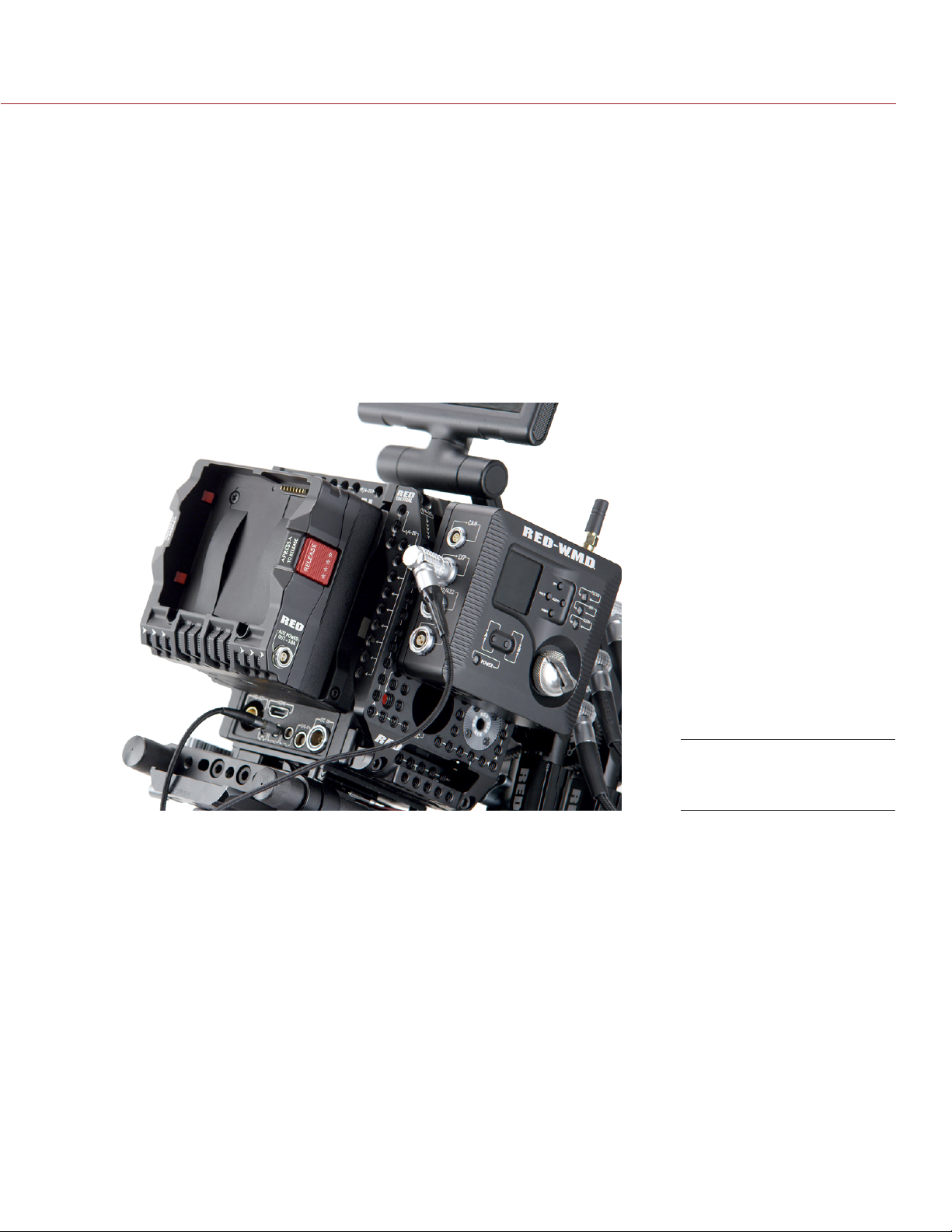
CONNECT THE 3-AXIS SYSTEM
1. Connect the RED Lens Control Motors.
A. Connect the RED W.M.D. Motor Cable to the pivoting connector on each Lens Control Motor.
B. Connect the opposite end of the LENS CONTROL MOTOR CABLE to the desired lens function.
C. Repeat steps A and B for additional motors.
2. Connect the desired RED Start/Stop cable.
A. Connect the desired RED Start/Stop Cables to the W.M.D. EXP port.
B. Connect the desired RED Start/Stop Cables to the appropriate SYNC and CTRL ports on the BRAIN.
WARNING: DO NOT connect Start/Stop Cables to the CTRL port only. This may result in undesired consequences or cause the camera to crash.
NOTE: For more information, go to “Configure Start/Stop, Genlock, TimeCode, Tally” on page 27.
Connect RED
Start/Stop Cable
3. Connect power to the W.M.D.
A. Connect the desired W.M.D. Power Cable to the W.M.D. PWR port.
B. Connect the opposite end of the W.M.D. Power Cable to a 12 V DC power supply with sufficient am-
perage.
NOTE: It is recommended that you connect the W.M.D. to a dedicated power source, such as shore
power, when operating power intensive configurations or stiff lenses that require high torque settings.
NOTE: For more information, go to “Wireless Motor Driver (W.M.D.)” on page 16.
4. Connect the T.H.C.
A. Connect the 4-pin RED CAN Command Cable to the CAN connector port on the W.M.D.
B. Connect the opposite end of the RED CAN Command Cable to the T.H.C. (CAN) port.
C. Toggle the T.H.C. power switch to Cable mode.
NOTE: The W.M.D. communicates wireless settings information via the RED CAN Command Cable. For
more information, go to “Tactical Hand Controller (T.H.C.)” on page 32.
COPYRIGHT © 2014 RED.COM, INC 955-0044, REV-D | 13
Page 14

RED 3-AXIS SYSTEM OPERATION GUIDE
CONFIGURE THE 3-AXIS SYSTEM
1. Pair the T.H.C.
A. Ensure the RED CAN Command Cable is connected to the W.M.D. and T.H.C.
B. Toggle the T.H.C. power switch to Cable mode.
Once paired, the T.H.C. retains wireless information for that W.M.D.
C. Insert a charged RED Li Battery 7.2V.
D. Toggle the T.H.C. power switch to Battery mode.
Wait a few seconds for the T.H.C. wireless LED to turn solid blue, signalling a wireless connection.
E. Remove the RED CAN Command Cable.
The T.H.C. is now successfully paired.
NOTE: For more information, go to “Pair the T.H.C.” on page 37.
2. Set motor type.
A. In the W.M.D. main menu, navigate to Focus/Iris/Zoom > Model.
B. Select your motor type. (Example: RED DLM1)
NOTE: For more information, go to “Select Motor Type/Model” on page 25.
3. Configure wireless settings.
A. In the W.M.D. main menu, select Wireless.
If you are operating the T.H.C. in close proximity (Up to 25 feet), select Low.
If you are operating the T.H.C. from greater distances, select High.
If operating multiple systems in the same vicinity, select a unique wireless channel.
NOTE: For more information, go to “Configure Wireless Settings” on page 26.
4. Initialize motors.
A. Press and hold the Initialize button on the T.H.C., or the B button on the W.M.D. for two (2) seconds.
NOTE: Fore more information, go to “Initialize the System” on page 14.
The RED 3-Axis Lens Control System is now successfully setup and ready for wireless operation. The remainder of this section offers further guidance on initialization, motor configuration, lens profiles, metadata, and
T.H.C. controls.
INITIALIZE THE SYSTEM
Initialization detects the range of motion for each motor and stores the data in the W.M.D. Lens data remains in
W.M.D. for approximately 14 hours even if system reboots are performed. W.M.D. LEDs display motor initialization status. Red LEDs indicate motors that are not initialized, solid green indicates motors that are initialized,
and flashing green LEDs indicate an initialization process is in progress.
To initialize the system, perform one of the following actions:
Press and hold the Initialize button on the T.H.C. for two (2) seconds to initialize all connected motors.
Press and hold the B button on the W.M.D. for two (2) seconds to initialize all connected motors.
Press and release the Initialize or B button to initialize only motors that need it.
A single motor can be initialized by disconnecting and reconnecting the motor cable.
IMPORTANT: Initialize motors any time a modification is made.
NOTE: The W.M.D. must be unlocked for the B button to be active. Press and hold the A button for two (2) sec-
onds to unlock the unit and access the menu.
The RED 3-Axis Lens Control System is now successfully setup and ready for wireless operation. The remain-
der of this section offers guidance on non-essential features.
COPYRIGHT © 2014 RED.COM, INC
955-0044, REV-D | 14
Page 15

RED 3-AXIS SYSTEM OPERATION GUIDE
CONFIGURE LENS CONTROL MOTORS
The W.M.D. features a number of adjustments in the Focus, Iris, and Zoom menu topics to fine-tune specific
motor/lens combinations. After initializing the system, you may need to adjust the following settings:
Torque
Direction
Type/Model
Backlash
Endstop
NOTE: For more information, go to “Configure Focus, Iris, and Zoom Motors” on page 24.
METADATA AND LENS PROFILES
The microSD slot on the W.M.D. is used to update firmware, as well as save and share modified lens profiles
that allow you to view real-time metadata on the W.M.D. This guide offers information on the following topics:
Select a Lens Profile
Modify a Lens Profile
Clear the Active Lens Profile
View Lens Metadata
Export Lens Profiles
Import Lens Profiles
NOTE: For more information, go to “W.M.D. Lens Profiles” on page 28.
LENS LIMITS AND LENS LOCKS
The T.H.C. features several convenient and easy-to-use features for precision wireless control. This guide offers
information on the following topics:
Set a Lens Limit
Remove a Lens Limit
Set a Lens Lock
Remove a Lens Lock
NOTE: For more information, go to the chapter “Tactical Hand Controller (T.H.C.)” on page 32.
COPYRIGHT © 2014 RED.COM, INC 955-0044, REV-D | 15
Page 16
RED 3-AXIS SYSTEM OPERATION GUIDE
WIRELESS MOTOR
03
DRIVER (W.M.D.)
W.M.D. OVERVIEW
The RED® Wireless Motor Driver (W.M.D.) is the brain of the RED 3-Axis Lens Control System. The W.M.D.
receives control signals from the RED Tactical Hand Controller (T.H.C.) to drive up to three (3) RED
Lens Control MotorS. With the W.M.D., you can adjust the following settings for each motor:
Torque
Direction
Type/Model
Backlash
Endstop
R3D metadata integration is a standard on the W.M.D., allowing your recorded lens control information to carry
over into post-production. Expansion ports, tool-free installation, and start/stop connectivity make the W.M.D.
versatile and easy-to-use.
NOTE: DO NOT USE the Pro I/O Module to power the RED W.M.D. The Pro I/O Module does not provide enough
power and is not designed to support the W.M.D.
NOTE: For more information on compatibility, go to “3-Axis System Compatibility” on page 54.
NOTE: Go to the RED Downloads page at www.red.com/downloads for the latest firmware version, operation
guide, and other support resources.
COPYRIGHT © 2014 RED.COM, INC
RED W.M.D.
955-0044, REV-D | 16
Page 17

RED 3-AXIS SYSTEM OPERATION GUIDE
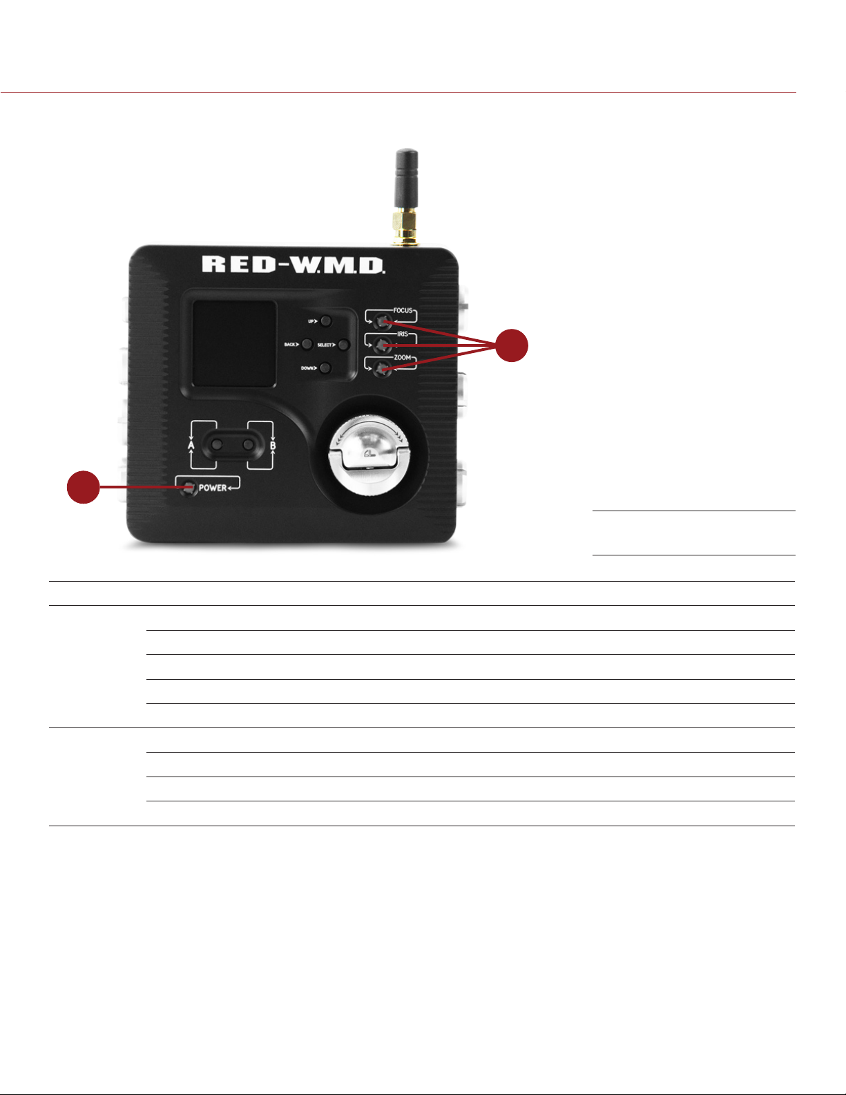
W.M.D. CONTROLS
4
1
5
6
7
2
3
# CONTROL DESCRIPTION
1 LCD display View the W.M.D. menus
2 A button Return to home screen; Toggles lock/unlock buttons
3 B button Short press initializes motors that are in an error state; long press initializes
all motors
4 Up button Navigate up through the W.M.D. main menus
8
W.M.D. Controls
5 Back button Return to the previous menu
6 Select button Enter or adjust the selected (highlighted) menu or item
7 Down button Navigate down through the W.M.D. main menus
8 Mounting
thumbscrew
COPYRIGHT © 2014 RED.COM, INC 955-0044, REV-D | 17
Press and turn to install (CW) or uninstall (CCW) the W.M.D. to a mounting
plate (Example: DSMC TACTICAL RIGHT PLATE)
Page 18
RED 3-AXIS SYSTEM OPERATION GUIDE
W.M.D. LEDS
2
1
# LED COLOR/FLASHING DESCRIPTION
1 Power Off No power connected
Green flashing Firmware upgrading
Green Power on; Firmware upgraded
Red Power error
Amber flashing System boot indicator or initialization in progress
2 Focus,
Iris,
Zoom
Off No motor connected
Green flashing Initialization in progress
Green Initialized and ready for operation
Red Motor error or failed initialization
W.M.D. LEDs
COPYRIGHT © 2014 RED.COM, INC
955-0044, REV-D | 18
Page 19
RED 3-AXIS SYSTEM OPERATION GUIDE
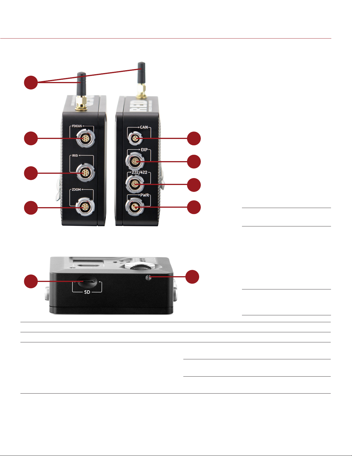
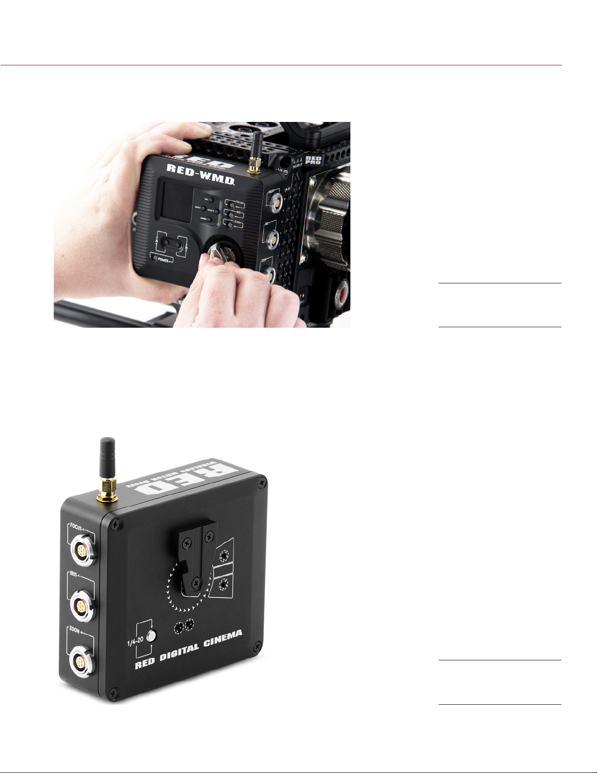
W.M.D. CONNECTORS
1
2
5
6
3
7
4
9
8
W.M.D. Connectors (Side)
10
W.M.D. Connectors
(Bottom)
# CONNECTOR DESCRIPTION COMPATIBLE PARTS PART NUMBERS
1 Wireless antenna Removeable antenna RED T.H.C./W.M.D. Antenna 790-0420
2 Focus connector
(7-pin 1B LEMO)
COPYRIGHT © 2014 RED.COM, INC 955-0044, REV-D | 19
Connect the W.M.D. to the
Focus Lens Control Motor
RED W.M.D. Motor Cable 7-Pin
Straight to 7-Pin Right (12”)
RED W.M.D. Motor Cable 7-Pin
Straight to 7-Pin Right (18”)
RED W.M.D. Motor Cable 7-Pin
Straight to 7-Pin Right (24”)
790-0434
790-0406
790-0412
Page 20

RED 3-AXIS SYSTEM OPERATION GUIDE
# CONNECTOR DESCRIPTION COMPATIBLE PARTS PART NUMBERS
3 Iris connector
(7-pin 1B LEMO)
4 Zoom connector
(7-pin 1B LEMO)
5 CAN connector
(4-pin 0B LEMO)
6 Expansion port
(14-pin 1B LEMO)
Connect the W.M.D. to the
Iris Lens Control Motor
Connect the W.M.D. to the
Zoom Lens Control Motor
CAN port for T.H.C. wired
communication
Expansion port to connect to
DSMC via the SYNC port and
control Start/Stop functions
on the DSMC
RED W.M.D. Motor Cable 7-Pin
Straight to 7-Pin Right (12”)
RED W.M.D. Motor Cable 7-Pin
Straight to 7-Pin Right (18”)
RED W.M.D. Motor Cable 7-Pin
Straight to 7-Pin Right (24”)
RED W.M.D. Motor Cable 7-Pin
Straight to 7-Pin Right (12”)
RED W.M.D. Motor Cable 7-Pin
Straight to 7-Pin Right (18”)
RED W.M.D. Motor Cable 7-Pin
Straight to 7-Pin Right (24”)
RED CAN Command Cable (5') 790-0407
RED CAN Command Cable (50') 790-0408
RED CAN Command Cable (100') 790-0409
RED Start/Stop Cable (1B to Sync,
Ctrl, BNC)
RED Start/Stop Cable (1B to BNC) 790-0416
790-0434
790-0406
790-0412
790-0434
790-0406
790-0412
790-0415
7 232/422 port
(10-pin LEMO)
8 PWR connector
(2-pin 1B LEMO)
9 MicroSD card slot MicroSD card slot for upgrad-
10 Guide pin 1/4" guide pin to install the V-
Serial port to communicate
with third-party devices
Power in RED W.M.D. Power Cable 2-Pin 1B
ing W.M.D. firmware
LOCK to a DSMC TACTICAL
RIGHT PLATE
RED Start/Stop Cable (1B to 00B
Sync)
3BNC-to-00 LEMO Sync Cable 790-0154
BNC-TO-BNC Adaptor 790-0435
N/A N/A
to 2-Pin 0B (18”)
RED W.M.D. Power Cable 2-Pin 1B
to 4-Pin XLR (8’)
MicroSD card N/A
1/4" guide pin N/A
790-0428
790-0410
790-0411
COPYRIGHT © 2014 RED.COM, INC
955-0044, REV-D | 20
Page 21
RED 3-AXIS SYSTEM OPERATION GUIDE
MOUNT THE W.M.D.
The W.M.D. is designed to support various mounting requirements, enabling you to customize your setup for
your own camera configuration.
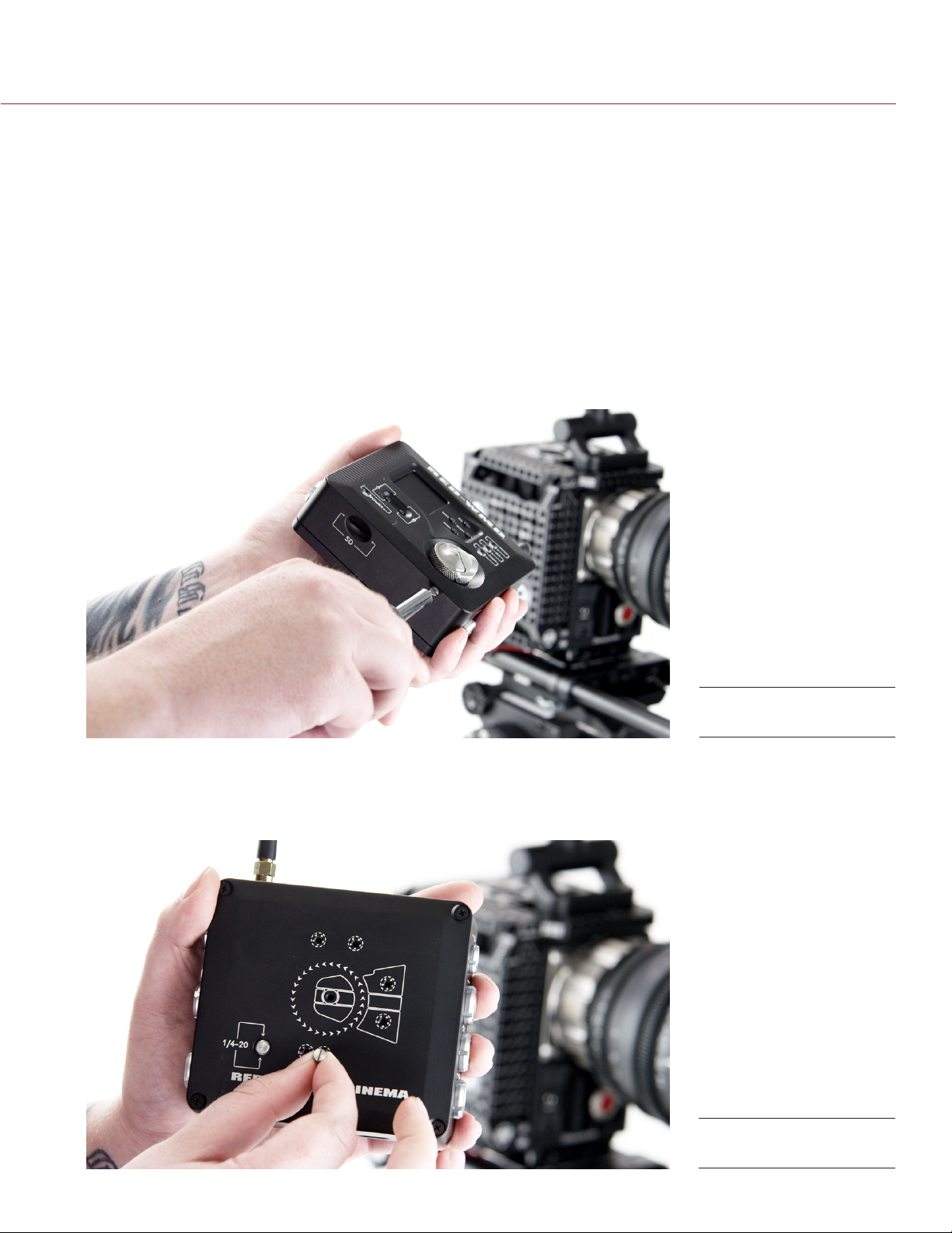
ATTACH THE W.M.D. TO THE DSMC TACTICAL RIGHT PLATE
When the V-LOCK is removed from the back of the W.M.D., it can be attached to a DSMC® Tactical Right Plate
using the built-in thumbscrew and guide pin.
The W.M.D. can be attached to a DSMC Tactical Right Plate or other mounting plate with 1/4-20 screw holes.
The built-in thumbscrew and 1/4" guide pin provide convenient, tool-free attachment for the W.M.D.
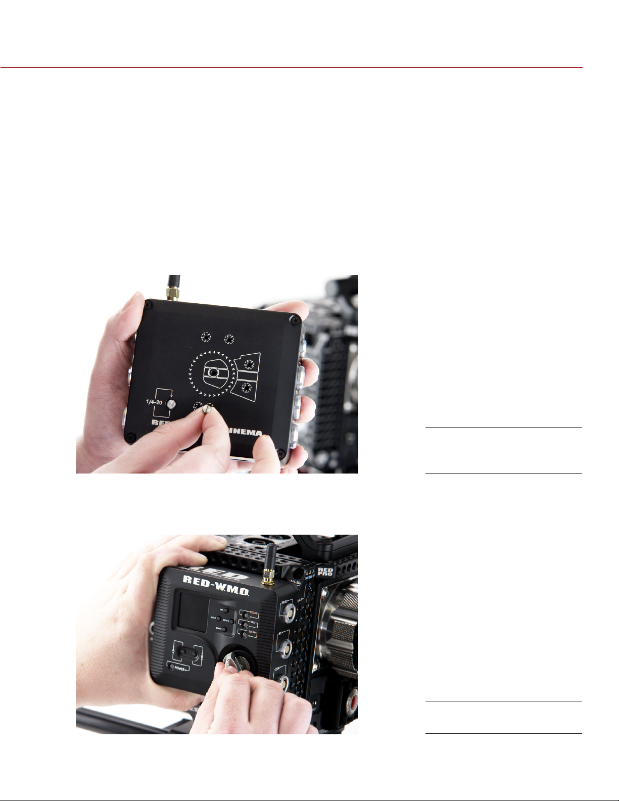
1. Ensure that the V-LOCK is removed from the back of the W.M.D. For more information about how to remove
the V-LOCK, go to “Mount the W.M.D. to a V-Mount Receiver” on page 22.
2. Use a slotted screwdriver to remove the guide pin from the bottom of the W.M.D.
Remove Guide Pin
3. Use a slotted screwdriver to install the guide pin in the appropriate mounting hole on the back of the W.M.D.
Select the mounting hole based on your mounting configuration:
‒ DSMC Tactical Right Plate: Use the screw hole closest to the 1/4-20 screw for 18 mm spacing.
‒ Third-party cheeseplate: Use the screw hole farthest from the 1/4-20 screw for 25 mm spacing.
Install Guide Pin
COPYRIGHT © 2014 RED.COM, INC 955-0044, REV-D | 21
Page 22
RED 3-AXIS SYSTEM OPERATION GUIDE
4. Place the W.M.D. against the Tactical Plate so that the guide pin and 1/4-20 screw each align with a 1/420 screw hole.
5. Push and turn the W.M.D. 1/4-20 thumbscrew until it is hand-tight. DO NOT OVERTIGHTEN.
Push and Turn
Thumbscrew
MOUNT THE W.M.D. TO A V-MOUNT RECEIVER
The W.M.D. ships with a V-LOCK to mount the W.M.D. to most industry-standard female v-mount receivers.
1. Align the V-LOCK in the desired position on the back of the W.M.D.
2. Use a Phillips #1 screwdriver to install three (3) M3x0.5 x 8 mm flathead screws that attach the V-LOCK to
the W.M.D. Fully tighten. DO NOT OVERTIGHTEN.
Use a Phillips #1 screwdriver to remove the three (3) M3x0.5 x 8 mm flathead screws, when finished.
COPYRIGHT © 2014 RED.COM, INC
W.M.D. Rear
(V-LOCK Installed)
955-0044, REV-D | 22
Page 23

RED 3-AXIS SYSTEM OPERATION GUIDE
POWER THE W.M.D.
1. Connect the 2-pin 1B LEMO connector of a RED W.M.D. Power Cable to the PWR port on the W.M.D.
2. Connect the opposite end to a 12 V DC power source with sufficient amperage.
NOTE: The W.M.D. is powered on when the power cable is connected to a live power source. Disconnect
the power cable to turn off the W.M.D.
CONNECT MOTORS
1. Connect a RED W.M.D. Motor Cable to the 7-pin LEMO connector on the motor.
2. Connect the opposite end of the RED W.M.D. Motor Cable to the corresponding lens function (Focus, Iris,
Zoom) 7-pin LEMO connector on the W.M.D.
3. After connecting all motors to the W.M.D., configure the settings for that motor. For more information about
configuring motor settings, go to “Configure Focus, Iris, and Zoom Motors” on page 24.
INITIALIZE WITH THE W.M.D.
Motor initialization detects each motor’s range of motion for the attached lens and stores the encoder positions and lens parameters within the W.M.D. lens data gathered by the initialization process remains in W.M.D.
memory for approximately 14 hours, even if system reboots are performed. This 14 hour period begins when
the W.M.D. is powered off for the first time.
To initialize ALL motors:
Press and hold the B button on the W.M.D. for two (2) seconds.
To initialize ONLY motors with unrecognized positions:
Press and release the B button.
A single motor can be initialized by disconnecting and reconnecting the motor cable.
WARNING: It is important to initialize every time a change is made to a lens or a motor. Failing to initialize may
damage lenses or motors.
COPYRIGHT © 2014 RED.COM, INC 955-0044, REV-D | 23
Page 24

RED 3-AXIS SYSTEM OPERATION GUIDE
W.M.D. MAIN MENU
The W.M.D. home screen displays the following system information for convenient user access:
Lock status icon
Wireless power setting icon
‒ H: Wireless power set to High
‒ L: Wireless power set to Low
Currently selected lens profile
‒ White: Designates a default profile
‒ Yellow: Designates a modified AND saved User profile
‒ Red: Designates a modified profile that has not been saved
When changes are made to these W.M.D. main menu settings, they automatically update on the home screen.
AUTO-LOCK FEATURE
The W.M.D. features a menu lock function to prevent inadvertent changes to system settings. When locked, the
lock status indicator is displayed in the upper left corner of the W.M.D. home screen.
The W.M.D. automatically locks after 60 seconds of non-use. Press the A button from any W.M.D. menu to lock
the W.M.D. and return to the home screen.
UNLOCK THE W.M.D.
When the W.M.D. is locked, only the A button remains active. Unlock the W.M.D. to return to the main menu.
Press and hold the A button for two (2) seconds to unlock W.M.D.
W.M.D. BUTTON LOCK
In the W.M.D. Options menu, the Button Lock feature provides the user with the ability to disable the auto-lock
feature when a menu time-out occurs. When the lock is disabled, the user no longer has to hold the A button
for two (2) seconds to unlock the unit. Regardless of the setting, pressing the A button will lock the W.M.D.
Disable the auto-lock in the W.M.D. menu, under Options > Button Lock.
CONFIGURE FOCUS, IRIS, AND ZOOM MOTORS
After initializing the W.M.D. with a Lens Control Motor, you may need to adjust the following settings:
Torque
Direction
Type/Model
Backlash
Endstop
ADJUST TORQUE
Keep the torque setting as low as possible to avoid damaging the lens and lens motors. Increase the torque
setting if the motor does not successfully initialize or an error message is displayed.
1. In the W.M.D. main menu, select the desired motor. (Example: Focus, Iris, Zoom)
2. Select Torque.
3. Press Select to cycle through to the desired torque setting. (Example: Low, Medium, High)
COPYRIGHT © 2014 RED.COM, INC
955-0044, REV-D | 24
Page 25

RED 3-AXIS SYSTEM OPERATION GUIDE
CHANGE MOTOR DIRECTION
The last direction of the motor persists between reboots.
1. In the W.M.D. main menu, select the desired motor. (Example: Focus, Iris, Zoom)
2. Select Direction.
3. Press Select to toggle to motor direction. (Example: CW, CCW)
SELECT MOTOR TYPE/MODEL
1. In the W.M.D. main menu, select the lens function for the specific motor. (Example: Focus, Iris, or Zoom)
2. Select Model.
3. Navigate to the desired motor model.
4. Press Select.
NOTE: For a list of default motor profiles, go to “3-Axis System Compatibility” on page 54 or the “W.M.D.
Main Menu Map” on page 70.
ADJUST BACKLASH
The RED Lens Control Motor offers next to zero backlash when properly installed. However, you may experience backlash with third-party motors, or certain lens and motor combinations.
The W.M.D. allows you to compensate for any backlash. Select an anti-backlash setting in the range of 0–3,000
encoder counts.
1. In the W.M.D. main menu, select the lens function for the specific motor. (Example: Focus, Iris, or Zoom)
2. Select Backlash.
3. Use the Select and Back buttons to navigate between digit values.
‒ Press Select to move the cursor to the right one (1) digit.
‒ Press Back to move the cursor to the left one (1) digit.
‒ Press Up to increase the value or press Down to decrease the value.
4. Adjust the setting until backlash is removed.
5. Deselect the digits and return to the menu.
ADJUST ENDSTOP
The W.M.D. provides a buffer for the endstops. However, different lenses have varying requirements for this
buffer. Some lenses require the motor to drive the lens right up to the endstop. Other lenses do not require this
and allow a large buffer to prevent high speed moves from overshooting into the end stop.
The W.M.D. allows you to compensate for the endstop buffer range. Select an endstop setting in the range of
0-3,000 encoder counts.
1. In the W.M.D. main menu, select the lens function for the specific motor. (Example: Focus, Iris, or Zoom)
2. Select Endstop.
3. Use the Select and Back buttons to navigate between digit values.
‒ Press Select to move the cursor to the right one (1) digit.
‒ Press Back to move the cursor to the left one (1) digit.
‒ Press Up to increase the value or press Down to decrease the value.
4. Adjust the setting as needed.
5. Deselect the digits and return to the menu.
COPYRIGHT © 2014 RED.COM, INC 955-0044, REV-D | 25
Page 26

RED 3-AXIS SYSTEM OPERATION GUIDE
CONFIGURE WIRELESS SETTINGS
In order for the T.H.C. to control the W.M.D., the RED 3-Axis Lens Control System uses a Frequency-Hopping
Spread Spectrum (FHSS) wireless link and offers 42 channels.
1. In the W.M.D. main menu, select Wireless.
2. Select a Channel. The range is 1–42.
3. Select a power setting for the strength of the wireless signal.
‒ Low: The low power setting balances range and low power and is appropriate in most cases.
‒ High: For maximum range, the high power setting can be used.
NOTE: Be sure to set W.M.D. wireless settings appropriately. If the W.M.D. wireless setting is set to High,
the T.H.C. may not perform as desired or may lose connection if operating in close proximity to the W.M.D.
When using wireless on high, the T.H.C. should be at least one meter from the W.M.D. for proper operation.
VIEW MOTOR STATUS
This section describes each motor status and provides tips on how to resolve issues if an error occurs.
In the W.M.D. main menu, select Status to view the state of each motor.
MOTOR STATUS DESCRIPTION/POSSIBLE CAUSES TROUBLESHOOTING OPTIONS
— Motor not detected Disconnect and reconnect the motor to
the W.M.D.
Ensure that the LEMO connectors on
both ends of the cable are fully seated
and locked
Bad PWM W.M.D. cannot detect that the motor is
moving
Torque setting is too high for the lens
Bad cable or malfunctioning motor
Homing W.M.D. cannot find the endstops after mov-
ing the motor for 40 seconds
OK Motor functioning correctly N/A
Over Drive Incorrect parameters are being used for mo-
tor acceleration
Over Torque Motor was disengaged and reengaged
without re-initializing the motor, which al-
lowed the motor to drive into a hard stop
Lens is obstructed and cannot move
Torque setting is too low for the lens
Decrease torque until the status changes
to “OK”
Ensure that the correct motor model is
selected in the W.M.D. main menu
Try a different RED W.M.D. Motor Cable
Try a different motor
Ensure that the teeth on the motor drive
gear fully mesh with the teeth on the lens
gear
Ensure that the pin on the motor drive
gear properly engages the slot on the
motor hub
Ensure that all motor parameters are
properly selected in the W.M.D.
Initialize the motor
Ensure that lens movement is not ob-
structed
Increase torque and initialize
COPYRIGHT © 2014 RED.COM, INC
955-0044, REV-D | 26
Page 27

RED 3-AXIS SYSTEM OPERATION GUIDE
CONFIGURE START/STOP, GENLOCK, TIMECODE, TALLY
This section explains how to set up start/stop, genlock, and timecode with the W.M.D. and a DSMC.
For more information about cables and configurations, go to “3-Axis System Cables” on page 63.
1. Configure Start/Stop in the DSMC menu.
A. Go to Menu > Settings > Setup > GPIO/Sync > Brain GPIO.
B. Select General Purpose In from the Camera In drop-down menu.
2. Connect the appropriate RED Start/Stop Cables for your desired configuration.
FUNCTIONS CABLE PART NUMBERS HOW TO CONNECT
Start/Stop,
Genlock,
Timecode,
and Tally
Start/Stop,
Genlock,
and Timecode
Start/Stop RED Start/Stop Cable
RED Start/Stop Cable
(1B to Sync, Ctrl, BNC)
3BNC-to-00 LEMO Sync
Cable
RED Start/Stop Cable
(1B to BNC)
3BNC-to-00 LEMO Sync
Cable
(1B to 00B Sync)
790-0415 1. Connect the 14-pin 1B LEMO to the EXP
port on the W.M.D.
2. Connect the 4-pin LEMO start/stop con-
nector to the CTRL port on the DSMC
BRAIN
3. Connect the BNC connector to the
White BNC connector of the 3BNCto-00 LEMO Sync Cable using a BNCTO-BNC Adaptor (included with the
RED 3-Axis Lens Control System)
790-0154 4. Connect the 4-pin 00 LEMO connector to
the SYNC port on the DSMC BRAIN
790-0416 1. Connect the 14-pin 1B LEMO to the EXP
port on the W.M.D.
2. Connect the BNC connector to the
White BNC connector of the 3BNCto-00 LEMO Sync Cable using a BNCTO-BNC Adaptor (included with the
RED 3-Axis Lens Control System)
790-0154 3. Connect the 4-pin 00 LEMO connector to
the SYNC port on the DSMC BRAIN
790-0428 1. Connect the 14-pin 1B LEMO to the EXP
port on the W.M.D.
2. Connect the 4-pin 00 LEMO connector to
the SYNC port on the DSMC BRAIN
COPYRIGHT © 2014 RED.COM, INC 955-0044, REV-D | 27
Page 28

RED 3-AXIS SYSTEM OPERATION GUIDE
3. Configure Start/Stop in the W.M.D. main menu.
A. Select Start/Stop.
B. Select a start/stop option based on the intended functionality and cables used.
FUNCTIONS START/STOP CABLE PART NUMBER TYPE
Disable Start/Stop N/A N/A Off
Start/Stop, Genlock, Time-
code, and Tally with DSMC
Start/Stop, Genlock, and
Timecode with DSMC
Start/Stop with DSMC RED Start/Stop Cable (1B to 00B Sync) 790-0428 EPIC
Start/Stop
with RED ONE
C. Press Select.
RED Start/Stop Cable (1B to Sync, Ctrl,
BNC)
RED Start/Stop Cable (1B to BNC) 790-0416 EPIC
RED currently does not provide start/
stop cables to connect the W.M.D. to the
RED ONE
790-0415 EPIC+Tally
N/A RED ONE
W.M.D. LENS PROFILES
The W.M.D. includes default lens profiles, as well as the capability to modify default profiles for fine tuning. Lens
profiles are separated into three (3) menu categories, Prime (default), Zoom (default), and User (modified). If a
modification is made to a lens profile, the modified version can be saved under the User category.
NOTE: If a particular lens does not have a default profile, the W.M.D. will not support metadata. It may still be
compatible with the system. For more information, go to “3-Axis System Compatibility” on page 54.
The following lenses are supported with default profiles in the W.M.D. firmware:
PRIME LENSES
ARRI Ultra Prime: 14mm, 16mm, 20mm, 24mm, 28mm, 32mm, 50mm, 65mm, 85mm, 100mm, 135mm
ARRI Master Prime: 14mm, 16mm, 18mm, 21mm, 25mm, 27mm, 50mm, 65mm, 75mm, 150mm
Cooke S5: 25mm, 32mm, 50mm, 75mm
Cooke S4: 14mm, 18mm, 21mm, 25mm, 27mm, 32mm, 35mm, 50mm, 65mm, 75mm, 100mm, 300mm
Elite Digital: 18mm, 24mm, 35mm, 50mm, 75mm, 100mm, 135mm
Leica Summilux-C: 21mm, 25mm, 40mm, 50mm, 75mm, 100mm
RED PRO PRIME: 18mm, 25mm, 35mm, 50mm, 85mm, 100mm, 300mm
ZOOM LENSES
Angénieux Optimo: 15-40mm, 17-80mm, 30-80mm
ARRI/Fujinon Alura: 18-80mm T2.6
Fujinon Cine: 14.5-45mm T2, 19-90mm
RED ZOOM: 17-50mm, 18-85mm, 18-50mm T3, 50-150mm T3
COPYRIGHT © 2014 RED.COM, INC
955-0044, REV-D | 28
Page 29

RED 3-AXIS SYSTEM OPERATION GUIDE
SELECT A LENS PROFILE
Default lens profiles are located Prime or Zoom menus. Modified lens profiles are saved in the User menu.
1. In the W.M.D. main menu, select Profiles.
2. Select the desired lens profile type. (Example: Prime, Zoom, or User)
3. Select the manufacturer.
4. Select the model.
5. Select the focal length.
6. Press Select to choose the lens profile for the specific lens.
Select a Lens Profile
CLEAR THE ACTIVE LENS PROFILES
The clear function deselects the current lens profiles. This will clear the active profile. Reselect a lens profile if
you wish to view metadata.
1. In the W.M.D. main menu, select Profiles.
2. Select Clear.
3. Press Back to exit to the Profiles menu.
Or press A to lock the W.M.D. and return to the home screen.
MODIFY A LENS PROFILE
The W.M.D. allows you to modify the encoder position related to a specific data point to fine-tune the active
lens profile.
1. In the W.M.D. main menu, select Profiles.
2. Select Modify.
NOTE: The 60 second auto-lock feature is disabled while the Modify menu is open.
3. Select the desired lens function. (Example: Focus, Iris, or Zoom)
4. Perform fine-tuning adjustments to calibrate the selected lens.
A. Adjust the gear so that the physical marking on the lens matches the “Mrk” value on the W.M.D. screen.
B. Press Select to update. The updated encoder position “At” value, should now match the “Mrk” value.
C. Repeat for each focal position on the lens as needed.
5. Press Down to save the profile and exit to the Profiles menu.
Or press Back to exit to the Profiles menu without saving lens profile changes.
Or press A to lock the W.M.D. and return to the home screen. This does not save lens profile changes.
COPYRIGHT © 2014 RED.COM, INC 955-0044, REV-D | 29
Page 30

RED 3-AXIS SYSTEM OPERATION GUIDE
SAVE A LENS PROFILE
If you have made lens profile modifications but did not save changes at the time, follow these steps to save
your changes.
1. In the W.M.D. main menu, select Profiles.
2. Select Save.
VIEW LENS METADATA
Metadata format is dependent on your lens profile setting:
Lens profile is selected (Select > Profiles): Focus, Iris, and Zoom data extrapolated from the motor encoder
positions displays for each lens function (Focus, Iris, Zoom).
Lens profile NOT selected: Hexadecimal motor position data displays for each lens function (Focus, Iris,
Zoom).
Once a lens profile is selected, you can view lens metadata on the W.M.D. screen.
1. In the W.M.D. main menu, select Metadata.
NOTE: If a lens does not support a particular lens function (Example: prime lenses do not have zoom) or a motor
is not connected, the resulting value is displayed as a hexadecimal value.
EXPORT LENS PROFILES
Use the export function to save modified profiles to the microSD card for repeat use and sharing.
1. In the W.M.D. main menu, select Profiles > Save.
2. Select Export.
3. Choose one of the following options:
‒ Overwrite: Exports all profiles, overwriting any differences on the microSD. Saves existing profiles.
‒ Keep: Adds W.M.D. profile library to existing microSD contents.
‒ Only: Clears the microSD and replaces contents with the existing W.M.D. profile library.
The W.M.D. displays “success” when the export is complete.
4. Press Back to exit, or press A to lock the W.M.D. and return to the home screen.
5. Remove the microSD card.
IMPORT LENS PROFILES
Use the import function to load modified profiles onto the W.M.D. from the microSD card.
1. Ensure that the desired profile “.pfl” files are loaded on the microSD card.
2. Insert the microSD card into the W.M.D.
3. In the W.M.D. main menu, select Profiles > Import.
4. Choose one of the following options:
‒ Overwrite: Imports all profiles, overwriting any differences on the W.M.D. Saves existing profiles.
‒ Keep: Adds microSD contents to existing W.M.D. profile library.
‒ Only: Clears the W.M.D. and rebuilds profile library with microSD contents.
The W.M.D. displays “success” when the import is complete.
5. Press Back to exit, or press A to lock the W.M.D. and return to the home screen.
COPYRIGHT © 2014 RED.COM, INC
955-0044, REV-D | 30
Page 31

RED 3-AXIS SYSTEM OPERATION GUIDE
MANAGE LENS PROFILES
The W.M.D. automatically reads lens information and renames the profile on import. This effectively removes
any custom profile names. (Example: A renamed RED PRO PRIME 50mm lens profile is automatically renamed
to RED-PRIME-50mm.pfl when imported to the W.M.D.) For this reason, we recommend saving .pfl files in custom named folders, rather than changing the lens profile name.
Once you have exported lens profiles from the W.M.D. save them to your computer.
1. Insert the microSD card into your computer. Use a microSD to SD adapter, if necessary.
2. Save the .pfl files to a safe location on your computer.
A. Create a new folder on your desktop and label it appropriately. (Example: “WMD_Jun8”)
B. Place .pfl files into the new folder.
ACCESS W.M.D. DIAGNOSTIC DATA
Hardware status data for each W.M.D. component is found in the “About” menu. If you contact RED for support,
a RED representative may ask you for the hardware status of the W.M.D.
1. In the W.M.D. main menu, select About.
ERASE SETTINGS ON THE W.M.D.
If you are experiencing problems with the W.M.D. or for other reasons want to reset the unit to factory default
settings, perform the following steps:
1. In the W.M.D. main menu, select Options.
2. Select Erase Settings.
NOTE: Erasing settings will delete all existing User profiles and other adjustments that have been made on
the W.M.D. It is recommended that you export User profiles and save them to your computer before performing this operation.
COPYRIGHT © 2014 RED.COM, INC 955-0044, REV-D | 31
Page 32

RED 3-AXIS SYSTEM OPERATION GUIDE
TACTICAL HAND
04
CONTROLLER (T.H.C.)
T.H.C. OVERVIEW
The RED Tactical Hand Controller (T.H.C.) works with the RED Wireless Motor Driver (W.M.D.) and RED
Lens Control Motor to provide wireless operation of lens adjustments (Focus, Iris, Zoom). The T.H.C. delivers
on-the-fly precision tuning with independent Focus, Iris, and Zoom adjustment controls.
Up to two (2) T.H.C. units can be paired with a W.M.D. for individual operator control during shoots. The T.H.C.
uses a 2.4GHz Frequency-Hopping Spread Spectrum (FHSS) wireless link with multiple channel support. The
T.H.C. also features a field replaceable marking ring for convenient lens adjustments. A lanyard loop provides
a secure place to attach the T.H.C. to a lanyard or wristband.
The Tactical Hand Controller is also compatible with the REDLINK™ Bridge for wireless Iris and Focus control
of supported Canon® and Nikon® motorized lenses. For more information, see the REDLINK™ Bridge Operation
Guide, available at www.red.com/downloads.
NOTE: Go to the RED Downloads page at www.red.com/downloads for the latest firmware version, operation
guide, and other support resources.
COPYRIGHT © 2014 RED.COM, INC
RED T.H.C. Kit
955-0044, REV-D | 32
Page 33

RED 3-AXIS SYSTEM OPERATION GUIDE
T.H.C. CONTROLS
1
2
4
3
5
6
T.H.C. Controls
7
8
9
10
T.H.C. Controls
# CONTROL DESCRIPTION
1 Run button Record button for mobile Start/Stop
2 Iris slider
3 Zoom wheel
4 Initialize button Press and hold for two (2) seconds to initialize the system;
5 Power switch Toggles power source from cabled to battery mode
1
1
Adjusts motor connected to Iris port
Adjusts motor connected to Zoom port
OR press and release to initialize only motors unknown positions
(Must be paired or connected via CAN cable)
6 Zoom Limit button Hold down to set the “zoom” lens limit or lens lock
7 Focus wheel
8 Iris Limit button Hold down to set the “iris” lens limit or lens lock
9 Focus Limit button Hold down to set the “focus” lens limit or lens lock
10 Eject battery release Press to release the rechargeable battery from the T.H.C.
1. Focus, Iris, and Zoom controls can be used interchangeably by connecting the Lens Control Motor to the desired lens function connec-
tor on the W.M.D.
COPYRIGHT © 2014 RED.COM, INC 955-0044, REV-D | 33
1
Adjusts motor connected Focus port
Page 34

RED 3-AXIS SYSTEM OPERATION GUIDE
T.H.C. LEDS
1
2
3
4
T.H.C. LEDs
5
6
7
# LED COLOR/FLASHING DESCRIPTION
1 Focus Limit Off Function active; no limits set
Green flashing (slow) Actively setting limit (User is holding the limit button down)
Green flashing (fast) Function locked: no position updates are sent to the W.M.D.
Green Limit is enabled
2 Iris Limit Off Function active; no limits set
Green flashing (slow) Actively setting limit (User is holding the limit button down)
Green flashing (fast) Function locked: no position updates are sent to the W.M.D.
Green Limit is enabled
3 Wireless Off Off/wired connection; not attempting to connect
Blue flashing Attempting to connect to W.M.D.
T.H.C. LEDs
Blue Connected to W.M.D.
COPYRIGHT © 2014 RED.COM, INC
955-0044, REV-D | 34
Page 35

RED 3-AXIS SYSTEM OPERATION GUIDE
# LED COLOR/FLASHING DESCRIPTION
4 Battery/Tally1Green Charged battery
Amber Low battery
Red Very low battery (replace immediately to avoid power loss)
Flashing Tally on; camera is recording
Solid Tally off; camera is not recording
5 Initialize Off One or motor motors must be initialized; no motors detected
Green flashing Initialization in process
Green All detected motors are initialized
6 Power Off Power off
Green Power on
7 Zoom Limit Off Function active; no limits set
Green flashing (slow) Actively setting limit (User is holding the limit button down)
Green flashing (fast) Function locked: no position updates are sent to the W.M.D.
Green Limit is enabled
1. The tally feature is only supported with specific cabling configurations. Refer to “Configure Start/Stop, Genlock, TimeCode, Tally” on
page 27.
COPYRIGHT © 2014 RED.COM, INC 955-0044, REV-D | 35
Page 36

RED 3-AXIS SYSTEM OPERATION GUIDE
T.H.C. CONNECTORS
1
2
T.H.C. Wired Connections
5
3
4
T.H.C. Battery, microSD, and
Antenna
# CONNECTOR DESCRIPTION COMPATIBLE PARTS PART NUMBERS
1 AUX port Auxiliary power and communica-
tion for accessories (RS-232 at
38.4 K)
2 CAN port CAN communication and power RED CAN Command Cable (5') 790-0407
3 Battery compart-
ment
4 MicroSD slot
(under battery)
5 Wireless antenna Removeable antenna RED T.H.C./W.M.D. Antenna 790-0420
Holds the RED LI BATTERY 7.2V RED Li Battery 7.2V 740-0032
Standard microSD slot used to
upgrade T.H.C. firmware
RS232-to-RS232 Cable 790-0150
REDLINK-to-T.H.C. Connector
Cable (3')
RED CAN Command Cable (50') 790-0408
RED CAN Command Cable (100') 790-0409
Standard microSD N/A
790-0444
COPYRIGHT © 2014 RED.COM, INC
955-0044, REV-D | 36
Page 37

RED 3-AXIS SYSTEM OPERATION GUIDE
WIRED OPERATION
1. Connect the T.H.C. to the W.M.D. using the RED CAN Command Cable (provided).
2. Toggle the power switch to Cable mode.
The T.H.C. is now connected and ready for wired operation.
T.H.C. Wired Connection
PAIR THE T.H.C.
Connect and pair the T.H.C. with your W.M.D. to operate in wireless mode. Once paired, the T.H.C. stores
wireless information for that W.M.D. and automatically reconnects when in range. The T.H.C. retains the MAC
address information for a single W.M.D.
1. Ensure the W.M.D. is receiving power.
2. Connect the T.H.C. to the W.M.D. using a RED CAN Command Cable.
3. Toggle the power switch to Cable mode.
The T.H.C. automatically pairs when the W.M.D. is on.
4. Install a RED LI BATTERY 7.2V.
5. Toggle the T.H.C. power switch to Battery mode.
6. Remove the RED CAN Command Cable.
The T.H.C. searches for the wireless connection. The wireless LED stops flashing and remains solid blue
when connected.
NOTE: The RED CAN Command Cable also provides power to the T.H.C. up to approximately 500 ft. When using
a cable longer than 500 ft, insert a battery and toggle the power switch to Battery to provide sufficient power.
The CAN cable will continue to support serial communication over a much longer distance.
NOTE: For more information, go to “Configure Wireless Settings” on page 26.
COPYRIGHT © 2014 RED.COM, INC 955-0044, REV-D | 37
Page 38

RED 3-AXIS SYSTEM OPERATION GUIDE
CHANGE THE WIRELESS CHANNEL
1. Power off the T.H.C. by toggling the power switch to Cable mode.
2. Press and hold the Focus Limit button, and toggle the power switch to Battery mode.
3. After a few seconds, release Focus Limit. Iris Limit and Focus Limit LEDs flash corresponding to the current
channel setting:
‒ Iris Limit: Flashes to represent the tens.
‒ Focus Limit: Flashes to represent the ones.
For example, if the Iris LED flashes twice and the Focus LED flashes once, the current channel is 21.
4. After LEDs stop flashing, press the Iris Limit and Focus Limit buttons to set the new channel:
‒ Iris Limit: Press to set the tens.
‒ Focus Limit: Press to set the ones.
For example, to set the channel to 14, press the Iris button once, and press the Focus button four (4) times.
5. Wait a few seconds for the Iris Limit and Focus Limit LEDs to flash indicating the new channel.
NOTE: For more information, go to “Configure Wireless Settings” on page 26.
WIRELESS SETTINGS
The wireless settings for the T.H.C. are managed in the W.M.D. menu. If wireless settings are changed in the
W.M.D., the T.H.C. must be connected via a wired connection to obtain the new wireless information.
NOTE: For more information, go to “Configure Wireless Settings” on page 26.
CONNECT TWO (2) T.H.C. UNITS
The W.M.D. supports up to two (2) T.H.C. units. Both units have full control over all adjustment functions. Use
the lens lock function to prevent both controllers from sending conflicting commands while both units are in
operation.
Connect a second T.H.C. using the same method described in “Pair the T.H.C.” on page 37.
INITIALIZE WITH THE T.H.C.
The motor initialization process detects each motor’s range of motion for the equipped lens and stores the encoder position and effective range information within the W.M.D. Once stored, the settings remain in the W.M.D.
for approximately 14 hours.
To initialize ALL motors:
Press and hold the Initialize button on the T.H.C. for two (2) seconds.
To initialize ONLY motors with unrecognized positions:
Press and release the Initialize button.
A single motor can be initialized by disconnecting and reconnecting the motor cable.
WARNING: It is important to initialize the system every time a modification is made to a lens or a motor. Failing
to perform the initialization sequence may cause severe damage to your lens, motor, or camera.
COPYRIGHT © 2014 RED.COM, INC
955-0044, REV-D | 38
Page 39

RED 3-AXIS SYSTEM OPERATION GUIDE
SET A LENS LIMIT
The T.H.C. enables precision on-the-fly adjustments for lens functions.
1. Adjust the desired lens function knob/slider (Focus, Iris, or Zoom) to the min/max position.
(Example: zoomed out to capture full setting)
2. Press and hold the corresponding Limit button (Focus, Iris, or Zoom) on the T.H.C.
Hold Limit Button and Adjust
3. Adjust the corresponding lens function knob/slider (Focus, Iris, or Zoom) to the max/min position.
(Example: zoomed in on target)
4. Release the Limit button.
Press and release the corresponding Limit button to reinstate a previously set limit.
NOTE: The T.H.C. is a persistent state device, meaning that the lens limit will be maintained even if the unit is
powered down.
NOTE: When a lens limit button is held for three (3) seconds without a change made to the adjustment knob/
slider, the lens function limit will lock. For more information, go to “Set a Lens Lock” on page 40.
REMOVE A LENS LIMIT
1. Press and release the corresponding Limit button.
The lens limit is now deactivated. The LED turns off to indicate that the lens limit is not set.
Press and release the Limit button again to reset the limit.
NOTE: Holding down the limit button for three (3) seconds without any change to any input locks the respec-
tive lens adjustment function on that T.H.C. unit. For more information, go to “Set a Lens Lock” on page
40.
COPYRIGHT © 2014 RED.COM, INC 955-0044, REV-D | 39
Page 40

RED 3-AXIS SYSTEM OPERATION GUIDE
SET A LENS LOCK
The W.M.D. can support wireless communication with up to two (2) T.H.C. units at any given time. Use the lens
function lock feature on the T.H.C. to prevent accidental/unwanted manipulation of that lens function on your
T.H.C. unit.
1. Press and hold the Limit button for the desired lens function for three (3) seconds. DO NOT make adjust-
ments to the knob/slider during this time.
Hold Limit Button for 3 sec
2. Release the Limit button when the corresponding LED flashes green slowly.
The lens function is now locked for that T.H.C. unit. The lens function LED will flash green to signal an active lens lock.
REMOVE A LENS LOCK
1. Press and hold the Limit button for the desired lens function for three (3) seconds.
2. Release the Limit button once the corresponding LED becomes solid.
The lens function is now unlocked.
RECORD START/STOP WITH THE T.H.C.
The Battery/Tally LED, near the top of the T.H.C., flashes when the camera is recording.
1. Press and release the Run button to start recording.
2. Press and release the Run button again to stop recording.
NOTE: The Battery/Tally LED serves a dual purpose on the T.H.C. Flashing indicates that the camera is rolling, color indicates battery charge level.
COPYRIGHT © 2014 RED.COM, INC
955-0044, REV-D | 40
Page 41

RED 3-AXIS SYSTEM OPERATION GUIDE
LENS CONTROL
05
MOTOR
Lens ControL Motor oVerVIeW
The Lens Control Motor delivers precision control and flexibility in a slim, lightweight design. The
Lens Control Motor features dual-sided dovetail rails, a tool-free mounting clamp, and a rotating 7-pin LEMO
connector for space-saving low profile configuration. It is also engineered with adjustable torque settings,
mounting options for 15mm or 19mm support rods, and a magnetic-locking gear system to accommodate a
wide variety of lenses.
The RED Lens Control Motor is also compatible with third-party motor drivers using the appropriate RED motor cable with the proper resistance identification. For more information, visit the RED Store at http://www.red.
com/store or contact your Bomb Squad representative.
WArnInG: ALWAYS use the RED motor cable with the appropriate internal identification resistor when using RED
Lens Control Motors with third-party motor drivers. Any damage caused to motors or motor drivers resulting
from the use of third-party cables will not be covered under warranty.
note: For more information on compatibility, go to “Compatible Motor Drivers” on page 54.
This section provides information on the following Lens Control Motor components:
RED Lens Control Motor
RED Lens Control Motor Mounting Bracket
19mm-to-15mm Rod Reducer Kit
Lens Control Motor Gear M 0.8
COPYRIGHT © 2014 RED.COM, INC
Lens Control Motor with Lens Control Motor Mounting Bracket
955-0044, REV-D | 41
Page 42

RED 3-AXIS SYSTEM OPERATION GUIDE
Lens ControL Motor MoUntInG BrACKet
Mount the Lens Control Motor to 15mm or 19mm support rods using the flexible and tool-free Lens Control Motor Mounting Bracket. The bracket securely attaches to the built-in dove-tail mounting rails on the
Lens Control Motor. The bracket is designed for 19mm support rods and is also compatible with 15mm support
rods using snap-on reducer bushings.
Lens Control Motor Mounting
Bracket
19MM-to-15MM roD reDUCers
The 19mm-to-15mm Rod Reducers enable the Lens Control Motor Mounting Bracket to attach to 15 mm diameter support rods. Snap the 19mm-to-15mm Rod Reducers into the Lens Control Motor Mounting Bracket and
it will accommodate 15mm support rods.
19mm-to-15mm Rod Reducers
COPYRIGHT © 2014 RED.COM, INC
955-0044, REV-D | 42
Page 43

RED 3-AXIS SYSTEM OPERATION GUIDE
Lens DrIVe GeArs
RED Lens Drive Gears are magnetic-locking and interchangeable without the use of any tools. Additionally,
Lens Drive Gears can be installed on either side of a Lens Control Motor for optimized motor orientation and
low profile setup.
note: For more information, visit the RED Store at http://www.red.com/store or contact your Bomb Squad
representative.
RED Lens Drive Gear M 0.8
AttACH tHe Lens ControL Motor MoUntInG BrACKet
1. Align the dove-tail bracket on the Lens Control Motor Mounting Bracket with the desired mounting rail on
the Lens Control Motor.
2. Insert the Lens Control Motor Mounting Bracket and compress the locking guide pin to attach.
3. Slide the Lens Control Motor Mounting Bracket into place.
4. Tighten the adjustment knob to secure the Lens Control Motor Mounting Bracket into place.
reMoVe A Lens ControL Motor MoUntInG BrACKet
1. Loosen the adjustment knob to allow the Lens Control Motor Mounting Bracket to slide.
2. Compress the locking guide pin and slide the Lens Control Motor Mounting Bracket off of the dove-tail
mount.
InstALL tHe Lens ControL Motor
Dual dove-tail mounting rails on both sides of the Lens Control Motor offer flexible and convenient installation, regardless of your camera setup. With the Lens Control Motor Mounting Bracket attached to the
Lens Control Motor, perform the following steps:
1. Loosen the thumbscrew lock and open to clamp on the Lens Control Motor Mounting Bracket.
2. Install 19mm-to-15mm Rod Reducers (as necessary).
3. Position the Lens Control Motor Mounting Bracket on the support rod at the desired location. Ensure that
the Lens Control Motor gear can reach the desired lens adjustment gear.
note: Allow for a small amount of give between the motor gear and the lens adjustment gear when mounting the Lens Control Motor.
4. Close the clamp and move the pivoting Lens Control Motor Mounting Bracket lock into place.
5. Tighten the thumbscrew lock on the Lens Control Motor Mounting Bracket to secure the Lens Control Motor
to the support rod.
COPYRIGHT © 2014 RED.COM, INC 955-0044, REV-D | 43
Page 44

RED 3-AXIS SYSTEM OPERATION GUIDE
ConneCt tHe Lens ControL Motor
1. Connect a RED W.M.D. Motor Cable to the rotating connector on the Lens Control Motor.
2. Connect the opposite end of the RED W.M.D. Motor Cable to the corresponding lens function (Focus, Iris,
Zoom) 7-pin LEMO port on the W.M.D.
3. Retract the spring-loaded thumb latch to rotate the connector to the desired position.
4. Release the thumb latch and the rotating connector locks in place.
InstALL A Lens DrIVe GeAr
1. Insert the Lens Drive Gear mounting rod into the Lens Control Motor.
2. Twist the gear to align the guide pins.
3. Continue to apply light pressure, the gear magnetically snaps into place when properly aligned.
RED Lens Drive Gear M 0.8 Installed
reMoVe A Lens DrIVe GeAr
1. Push on the gear axle to eject the gear from the Lens Control Motor.
Alternatively, grasp the Lens Drive Gear by the gear teeth and pull to disengage and remove the gear.
COPYRIGHT © 2014 RED.COM, INC
955-0044, REV-D | 44
Page 45

RED 3-AXIS SYSTEM OPERATION GUIDE
SYSTEM
06
All RED products are designed for rugged durability, but precision instruments demand proper care. Please take
note the special care guidelines in this section.
WARNING: DO NOT attempt to modify, dismantle or open the Lens Control Motor, Tactical Hand Controller
(T.H.C.), Wireless Motor Driver (W.M.D.), or other accessory as doing so may expose you to electric shock and
serious injury. There are no user-serviceable parts inside. Alteration or repairs made to the Lens Control Motor,
T.H.C., W.M.D., or other accessory, except by a RED authorized service facility, will void the Limited Warranty.
MAINTENANCE
CLEAN 3-AXIS SYSTEM COMPONENTS
Clean ONLY using a dry cloth. When cleaning your Lens Control Motor, T.H.C., W.M.D., or other accessory,
remember that the components are not waterproof and moisture can damage electronic circuitry.
WARNING: DO NOT rinse or immerse any part of the Lens Control Motor, T.H.C., W.M.D., or other accessory.
Keep components dry at all times.
WARNING: DO NOT use soaps, detergents, ammonia, acetone, alkaline cleaners, abrasive cleaning compounds,
or solvents. These substances may damage electronic circuitry.
NOTE: Using any fastener or adhesive material may leave residue on equipment. If residue is left behind, use an
appropriate isopropyl alcohol cleaner and a lint-free cloth to clean. Apply a small amount of cleaning solution
to the lint-free cloth and wipe.
STORE THE 3-AXIS SYSTEM
It is important to properly store and protect your equipment when it is not in use. Use the following tips when
storing components of the RED 3-Axis Lens Control System:
Remove the detachable antenna from the T.H.C. and W.M.D. to prevent accidental damage to the antenna
and antenna connector.
Remove the battery from the T.H.C. When the battery is removed, ensure that dirt, dust, or other debris
does not get into the battery bay or the microSD slot.
COPYRIGHT © 2014 RED.COM, INC
955-0044, REV-D | 45
Page 46

RED 3-AXIS SYSTEM OPERATION GUIDE
UPGRADE
07
As part of RED Digital Cinema’s commitment to ongoing product support and development, the
Tactical Hand Controller (T.H.C.) and Wireless Motor Driver (W.M.D.) are designed to support firmware upgrades for improved functionality and additional features in the future.
The T.H.C. and W.M.D. are updated independently of each other. You can load both the T.H.C. and W.M.D.
firmware to the microSD card at the same time, since each device only reads its own firmware.
Visit www.red.com/downloads for the latest RED 3-Axis Lens Control System firmware and resources.
NOTE: User-selected settings on the T.H.C. and W.M.D. are not affected by firmware upgrades.
FIRMWARE
MICROSD CARD PREPARATION
Format the microSD card as MS-DOS FAT (for Mac) or FAT32 (for PC). The microSD card must be formatted
properly before saving firmware upgrade file.
Use the provided microSD card and SD card adaptor for best results when upgrading firmware. Oth-
er brands or models of microSD cards and SD card adaptors may not be compatible with the
RED 3-Axis Lens Control System.
VERIFY CURRENT W.M.D. FIRMWARE
The current firmware version can be found in the W.M.D. main menu.
1. In the W.M.D. main menu, navigate to the About menu.
2. Press Select.
The firmware version displays in green. A higher number reflects a later release version.
UPGRADE W.M.D.
IMPORTANT: If operating on battery power, ensure that the battery is fully charged before upgrading.
NOTE: User-selected settings on the T.H.C. and W.M.D. are not affected by firmware upgrades.
1. Insert the microSD card to the SD card adaptor.
2. Insert the SD card adaptor to the SD card slot on your computer or SD card reader.
3. Format the microSD card as MS-DOS FAT (for Mac) or FAT32 (for PC).
4. Download the most recent W.M.D. firmware from www.red.com/downloads.
NOTE: You can load both the T.H.C. and W.M.D. firmware to the microSD card at the same time, since each
device only reads its own firmware.
5. Save the firmware file to the root directory of the microSD card. Do not copy the file to a folder.
6. Power off the W.M.D.
7. Insert the microSD card in the microSD slot on the bottom of the W.M.D.
NOTE: Ensure the battery is fully charged before starting the firmware upgrade.
8. Power on the W.M.D.
The upgrade process starts when the W.M.D. is powered on. The upgrade status displays on the LCD dis-
COPYRIGHT © 2014 RED.COM, INC
955-0044, REV-D | 46
Page 47

RED 3-AXIS SYSTEM OPERATION GUIDE
play and the Power LED flashes green. When the upgrade is complete, the LCD display shows “Done” and
the Power LED turns solid green.
9. Power off the W.M.D.
10. Remove the microSD card.
VERIFY CURRENT T.H.C. FIRMWARE
There is currently no way to verify current firmware version. If you are experiencing problems, upgrade to the
latest firmware version available at www.red.com/downloads.
UPGRADE T.H.C.
IMPORTANT: Ensure that the battery is connected and fully charged. It is recommended that you also connect
the T.H.C. to a power source using the RED CAN COMMAND CABLE.
NOTE: User-selected settings on the T.H.C. and W.M.D. are not affected by firmware upgrades.
1. Insert the microSD card to the SD card adaptor.
2. Insert the SD card adaptor to the SD card slot on your computer or SD card reader.
3. The microSD card must be formatted each time before using it to upgrade. Format the microSD card as
MS-DOS FAT (for Mac) or FAT32 (for PC).
4. Download the most recent T.H.C. firmware from www.red.com/downloads.
NOTE: You can load both the T.H.C. and W.M.D. firmware to the microSD card at the same time, since each
device only reads its own firmware.
5. Save the firmware file to the root directory of the microSD card. Do not copy the file to a folder.
6. Power off the T.H.C.
7. Remove the battery to reveal the microSD slot in the battery bay.
8. Using your fingernail or other non-conductive material, move the microSD compartment to the open position and pull the hinged compartment open.
9. Insert the microSD card so that the contacts mate with the card reader connections on the T.H.C.
10. Close the microSD compartment.
11. Power the T.H.C. using the CAN cable or battery.
The upgrade process starts as soon as the T.H.C. is powered. The Battery LED flashes green rapidly for 15
seconds. When the upgrade is complete, the Battery LED turns solid green.
12. Power off the T.H.C.
13. Remove the microSD card.
COPYRIGHT © 2014 RED.COM, INC 955-0044, REV-D | 47
Page 48

RED 3-AXIS SYSTEM OPERATION GUIDE
TROUBLESHOOT
08
THE SYSTEM
GENERAL TOPICS
POWER FAILURE
SYMPTOM
The W.M.D. shuts off randomly during operation.
EXPLANATION
The 12 V auxiliary (AUX) port(s) on many DSMC® power modules, including the REDVOLT® XL MODULE, provide
a maximum of 3.8 A of current and is sufficient for most operating conditions. In certain instances, when driving
multiple motors simultaneously on a stiffer than normal lens, the W.M.D. may draw more than 3.8 A. This event
may cause an interruption of power supplied to the W.M.D. and result in a shutdown.
POTENTIAL RESOLUTIONS
Connect the W.M.D. to a 12 V DC power source with sufficient amperage.
Unplug a motor that is not being used for a particular shooting sequence. Removing a motor will reduce the
overall load on the W.M.D. during initialization, when not enough current is available.
OVER TORQUE MESSAGES AND POWER FAILURE
SYMPTOM
The DSMC monitor displays an error message stating that an over-torque situation has occurred and too much
current has been drawn from the camera. This results in the port ceasing to provide power.
EXPLANATION
In this instance, the DSMC notifies the user and removes power from that port. This may occur due to insufficient power sources or if you are using very stiff lenses that require high torque settings to adjust.
POTENTIAL RESOLUTIONS
Ensure that motors are set to the appropriate torque setting in the W.M.D. Main Menu. The low torque set-
ting may not be sufficient to rotate the lens gear. For more information, go to “Adjust Torque” on page 24.
Ensure that the lens is set to manual focus, if applicable.
NOTE: If you are using a very stiff lens and have already set the W.M.D. torque setting to High, then the lens
may not be compatible with the RED 3-Axis Lens Control System.
COPYRIGHT © 2014 RED.COM, INC
955-0044, REV-D | 48
Page 49

RED 3-AXIS SYSTEM OPERATION GUIDE
TROUBLESHOOT THE W.M.D.
W.M.D. DOES NOT RECOGNIZE MOTOR
SYMPTOM
The W.M.D. does not recognize a motor.
POTENTIAL RESOLUTIONS
Ensure that the W.M.D. is connected to the motor.
Ensure that the problem is not related to a faulty or damaged cable. Try connecting the W.M.D. and motor
with another cable.
Ensure that you are using a supported motor (for a list of supported motors, go to “3-Axis System Compat-
ibility” on page 54.
TROUBLESHOOT LENS CONTROL MOTORS
LENS CONTROL MOTOR GEAR SLIPS DURING OPERATION
SYMPTOM
A Lens Control Motor gear slips on the lens gear during operation.
EXPLANATION
Gear slips may occur due to support rod flexing when using carbon fiber support rods with lenses that are stiff
and require high torque levels. RED recommends using the BLACK ROD, STEEL ROD, or other stiff support
rods.
POTENTIAL RESOLUTIONS
Ensure that the gear is properly installed.
Ensure that the proper gear pitch is correct for the installed lens.
Ensure that support rods are firmly and properly installed.
Ensure that the Lens Control Motor and Lens Control Motor Mounting Bracket is properly installed and
tightened on the support rod.
The motor’s torque setting may be set too high. For more information, go to “Adjust Torque” on page 24.
LENS CONTROL MOTOR ERROR CODE
SYMPTOM
A Lens Control Motor is not functioning correctly or an error code is displayed.
POTENTIAL RESOLUTIONS
Navigate to Select > Status in the W.M.D. main menu and see if there is an error code.
Power cycle the W.M.D. to clear the error.
NOTE: For more information and resolutions regarding errors, go to “View Motor Status” on page 26.
COPYRIGHT © 2014 RED.COM, INC 955-0044, REV-D | 49
Page 50

RED 3-AXIS SYSTEM OPERATION GUIDE
LENS FUNCTION DOES NOT RESPOND
SYMPTOM
A lens function (Focus, Iris, Zoom) is not responding.
POTENTIAL RESOLUTIONS
The lens function may be locked. To resolve this issue, use the steps described in “Remove a Lens Lock”
on page 40.
Ensure the motor’s torque setting is set appropriately. The torque value may be too low.
Ensure you are using the appropriate motor cable.
If you are experiencing issues with the W.M.D., ensure that sufficient power is available for the operations.
Try connecting the W.M.D. to shore power and attempt the operation again.
TROUBLESHOOT WIRELESS OPERATIONS
T.H.C. DOES NOT PAIR WITH W.M.D.
SYMPTOM
The T.H.C. will not pair with the W.M.D.
EXPLANATION
The Tactical Hand Controller retains one (1) MAC address for the W.M.D. (or other controller) that it is connected to. Each W.M.D. can pair with up to two (2) T.H.C. units.
POTENTIAL RESOLUTION
Connect the T.H.C. to the W.M.D. using the RED CAN Command Cable.
1. Connect one end of the 4-pin 0B LEMO CAN connector cable to the CAN port on the W.M.D.
2. Connect the opposite end of the 4-pin 0B LEMO CAN connector cable to the CAN port on the T.H.C.
3. Ensure the wireless blue light stops flashing and turns off. This indicates that communication is established
and the wireless information has been exchanged.
INTERMITTENT WIRELESS SIGNAL
SYMPTOM
The wireless signal transmitting between the T.H.C. and W.M.D. is intermittent, resulting in intermittent or unreliable functionality.
POTENTIAL RESOLUTIONS
The W.M.D. wireless setting (Select > Wireless > Power) may need to change. When the T.H.C. is close to
the W.M.D., select Low. When the T.H.C. is farther away from the W.M.D., select High.
Ensure that the RED T.H.C./W.M.D. Antenna is securely connected to the T.H.C. and W.M.D.
A common cause for poor wireless connection is a low battery level in the T.H.C.
COPYRIGHT © 2014 RED.COM, INC
955-0044, REV-D | 50
Page 51

RED 3-AXIS SYSTEM OPERATION GUIDE
TROUBLESHOOT FIRMWARE UPGRADE
SYMPTOM
The W.M.D. or T.H.C. does not recognize the firmware upgrade file or is not upgrading properly.
POTENTIAL RESOLUTIONS
Start with a freshly formatted microSD card.
Ensure that there is no other data on the microSD card besides the upgrade file.
Use the microSD card provided by RED.
If you are unable to use the microSD card, you may need to experiment with different brands or models of
microSD cards or SD card adaptors.
Verify that the correct firmware file is downloaded to the root directory of the microSD card.
Verify that the microSD card is formatted as MS-DOS FAT (for Mac) or FAT32 (for PC).
COPYRIGHT © 2014 RED.COM, INC 955-0044, REV-D | 51
Page 52

RED 3-AXIS SYSTEM OPERATION GUIDE
TECHNICAL
A
SPECIFICATIONS
TacTical Hand conTroller (T.H.c.)
Dimensions Height (with antenna): 9.00 in. (228.6 mm)
Height (without antenna): 8.08 in. (205.2 mm)
Width: 3.50 in. (88.9 mm)
Depth: 4.32 in. (109.7 mm)
Weight 32.1 oz (885 g)
Material Aluminum
Construction Machined
Coating Black and red anodized coating
Operating Temperature Range 0˚C to 40˚C (32˚F to 104˚F)
Storage Temperature Range -20˚C to 50˚C (-4˚F to 122˚F)
Wireless Operating Frequency 2.4GHz FHSS
Input Supply Voltage 12 V to 18 V
Supported Battery Type RED® LI BATTERY 7.2V
Battery Capacity 2200 mAh at 7.2V
Wireless MoTor driver (W.M.d.)
Dimensions Height (with antenna): 4.95 in. (125.7 mm)
Height (without antenna): 4.05 in. (102.9 mm)
Width: 4.48 in. (113.8 mm)
Depth: 1.83 in. (46.5 mm)
Weight 19.2 oz (544 g)
Material Aluminum
Construction Machined
Coating Black anodized coating
Operating Temperature Range 0˚C to 40˚C (32˚F to 104˚F)
Storage Temperature Range -20˚C to 50˚C (-4˚F to 122˚F)
Frequency 2.4GHz FHSS
DC Power Supply Requirements 12 to 18 V DC
COPYRIGHT © 2014 RED.COM, INC
955-0044, REV-D | 52
Page 53

RED 3-AXIS SYSTEM OPERATION GUIDE
lens conTrol MoTor
Maximum Peak Torque 0.85 Nm
Maximum Speed 4.5 rev/second
Dimensions Height: 1.75 in. (44.5 mm)
Width: 1.00 in. (25.4 mm)
Depth: 4.50 in. (11.4 mm)
Weight 5.4 oz (155 g)
Material Aluminum
Construction Machined
Coating Black anodized coating
Operating Temperature
Storage Temperature -20˚C to 50˚C (-4˚F to 122˚F)
Typical Operating
Power Consumption < 10 W
Peak Operating
Power Consumption 25 W
1. The operating temperature range represents the low and high ambient temperature that the Lens Control Motor operates in without user-
intervention and is consistent with most other professional electronic imaging equipment. Extreme conditions require adequate preparation
and on-set handling. Any damage caused to the Lens Control Motor or your camera system caused by operating outside of the specified
temperature range is not covered under any RED warranty.
1
0˚C to 40˚C (32˚F to 104˚F)
red li BaTTerY 7.2v
Dimensions Height: 1.50 in. (38.1 mm)
Width: 0.80 in. (20.3 mm)
Depth: 2.20 in. (55.8 mm)
Weight 2.8 oz (78 g)
Battery Capacity 2200 mAh at 7.2 V
Rechargeable Yes
Operating Temperature Range 0˚C to 40˚C (32˚F to 104˚F)
Storage Temperature Range -20˚C to 50˚C (-4˚F to 122˚F)
COPYRIGHT © 2014 RED.COM, INC 955-0044, REV-D | 53
Page 54

RED 3-AXIS SYSTEM OPERATION GUIDE
3-AXIS SYSTEM
B
COMPATIBILITY
COMPATIBLE MOTORS
The following motors are currently supported by the RED® Wireless Motor Driver (W.M.D.) and RED
Tactical Hand Controller (T.H.C.):
RED Lens Control Motor (DLM1)
Element DLM1 (coming soon)
Heden M21VE
Heden M26VE
Preston DM1
Preston DM1x
Preston DM2
COMPATIBLE MOTOR DRIVERS
RED Lens Control Motors are compatible with the following motor drivers, which require a 3.3KΩ resistance,
using the RED Lens Motor Cable (3.3KΩ version):
Bartech® Focus Device, single-axis system
Preston® MDR1
Preston MDR2
Preston MDR3
cmotion® camin® motor drivers
WARNING: ALWAYS use the RED motor cable with the appropriate internal identification resistor when using RED
Lens Control Motors with third-party motor drivers. Any damage caused to motors or motor drivers resulting
from the use of third-party cables will not be covered under warranty.
NOTE: RED is in the process of testing and developing additional cables with the appropriate internal identification resistor to support seamless communication with other third-party motor systems.
COMPATIBLE LENSES
RED Lens Control Motors can be equipped with accessory drive gears to interface with lenses using any of the
following gear modules:
0.8 M
0.4 M
0.5 M
0.6 M
As with most lens control motors, there will be some lenses that will be too large, too heavy, or too stiff for the
motor. Additionally, cold ambient temperatures may also make it more difficult for the motor to rotate the lens.
NOTE: For information about lenses with default profiles, refer to “W.M.D. Lens Profiles” on page 28.
COPYRIGHT © 2014 RED.COM, INC
955-0044, REV-D | 54
Page 55

RED 3-AXIS SYSTEM OPERATION GUIDE
CONNECTOR AND
C
This appendix provides RED 3-Axis Lens Control System pinout information for the Wireless Motor Driver,
Tactical Hand Controller, Lens Control Motor as well as RED® connector cables that are used with the system
components.
NOTE: When connecting a cable to a connector, align the key and red marker on the cable connector with the
corresponding key and marker on the device connection.
NOTE: Connector diagram images are for reference only. Diagrams are not to scale.
CABLE PINOUTS
W.M.D. CONNECTORS
1
4
5
2
6
3
# CONNECTOR CONNECTOR TYPE CONNECTOR FUNCTION
1 FOCUS 7-pin 1B LEMO Lens motor drive support; Focus control knob on T.H.C.
2 IRIS 7-pin 1B LEMO Lens motor drive support; Iris control knob on T.H.C.
3 ZOOM 7-pin 1B LEMO Lens motor drive support; Zoom control slider on T.H.C.
4 CAN 4-pin 0B LEMO CAN communication and power for the T.H.C.
5 EXP 14-pin 1B LEMO Start/Stop, Tally, RS-232, GPIOs
6 232/422 10-pin 1B LEMO RS-232/422 communication
7
W.M.D. Connections
7 PWR 2-pin 1B LEMO 12 V to 18 V power
COPYRIGHT © 2014 RED.COM, INC
955-0044, REV-D | 55
Page 56

RED 3-AXIS SYSTEM OPERATION GUIDE
W.M.D. LENS MOTOR CONNECTOR
The W.M.D. Lens Motor connector is an industry-standard 7-pin 1B LEMO connector.
1 6
2
7 5
3
PIN SIGNAL
1 Motor (+)
2 Motor (-)
3 Encoder A
4 +5 V
5 GND
6 Encoder B
7 Motor ID
4
7-PIN 1B LEMO LENS DRIVE CONNECTOR
W.M.D. 7-Pin 1B lens drive connector
W.M.D. CAN CONNECTOR
The W.M.D. CAN connector is a 4-pin 0B LEMO connector that provides power and CAN communications between the W.M.D. and T.H.C., or other auxiliary devices.
1
2
PIN SIGNAL
COPYRIGHT © 2014 RED.COM, INC
4
3
1 GND
2 CANL
3 CANH
4 VCC
W.M.D. 4-Pin 0B CAN connector
4-PIN 0B LEMO CAN CONNECTOR
955-0044, REV-D | 56
Page 57

RED 3-AXIS SYSTEM OPERATION GUIDE
W.M.D. START/STOP/TALLY EXPANSION CONNECTOR
The W.M.D. Start/Stop/Tally expansion connector is a 14-pin 1B connector that provides expansion (EXP) support for the RED 3-Axis Lens Control System.
1 10
2 9
11
3
1412
8
13
4
5
PIN SIGNAL
1 GND
2 232_Rx
3 +12 V
4 232_TX
5 Momentary
6 EPIC Tally
7 EPIC Start/Stop
7
6
14-PIN 1B LEMO START/STOP EXPANSION CONNECTOR
Start/Stop
W.M.D. 14-Pin Start/Stop and Tally
connector
8 AUX GPIO 1_3.3
9 +3.3 V
10 Cable ID
11 12 AUX GPIO 2_3.3
13 14 -
COPYRIGHT © 2014 RED.COM, INC 955-0044, REV-D | 57
Page 58

RED 3-AXIS SYSTEM OPERATION GUIDE
W.M.D. AUX CONNECTOR
The W.M.D. AUX connector is a 10-pin 1B connector used for RS-232 communication and power with other
third-party systems and accessories.
1 8
72 9
3 6
10
4 5
PIN SIGNAL
1 Pwr Out
2 232 Tx
3 232 Rx
4 422 Tx+
5 422 Rx+
6 422 Rx-
7 422 Tx-
8 232 Jumper
9 232 Jumper
10 GND
W.M.D. 10-pin 0B RS232 connector
6-PIN 0B LEMO AUX CONNECTOR
COPYRIGHT © 2014 RED.COM, INC
955-0044, REV-D | 58
Page 59

RED 3-AXIS SYSTEM OPERATION GUIDE
W.M.D. POWER CONNECTOR
The W.M.D. PWR connector is a 2-pin 1B LEMO power connector to supply power to the W.M.D. from your
camera or other power modules.
1
2
W.M.D. 2-Pin 1B Power connector
2-PIN 1B LEMO POWER CONNECTOR
PIN SIGNAL
1 GND
2 +12 V
COPYRIGHT © 2014 RED.COM, INC 955-0044, REV-D | 59
Page 60

RED 3-AXIS SYSTEM OPERATION GUIDE
T.H.C. CONNECTORS
1
2
# CONNECTOR CONNECTOR TYPE CONNECTOR FUNCTION
1 AUX 6-pin 0B LEMO RS-232 communication to auxiliary devices
2 CAN 4-pin 1B LEMO CAN communication and power from the W.M.D.
T.H.C. Connections
T.H.C. AUX CONNECTOR
The T.H.C. AUX connector is a 6-pin 0B LEMO connector on the T.H.C. used for RS-232 communications and
power with third-party systems and accessories.
NOTE: The T.H.C. Auxiliary (AUX) connector is for future development and is not currently needed for operation.
1 6
52
3 4
T.H.C. 6-Pin 0B AUX Connector
6-PIN 0B LEMO AUX CONNECTOR
PIN SIGNAL
1 GND
2 Rx
3 Tx
4 Pwr Out
5 Pwr In
6 -
COPYRIGHT © 2014 RED.COM, INC
955-0044, REV-D | 60
Page 61

RED 3-AXIS SYSTEM OPERATION GUIDE
T.H.C. CAN CONNECTOR
The T.H.C. CAN connector is a 4-pin 0B LEMO connector that provides power and CAN communications between the W.M.D. and T.H.C., or other auxiliary devices.
1
2
PIN SIGNAL
4
3
1 GND
2 CANL
3 CANH
4 VCC
T.H.C. 4-Pin 0B CAN Connector
4-PIN 0B LEMO CAN CONNECTOR
COPYRIGHT © 2014 RED.COM, INC 955-0044, REV-D | 61
Page 62

RED 3-AXIS SYSTEM OPERATION GUIDE
LENS CONTROL MOTOR CONNECTORS
1
# CONNECTOR TYPE CONNECTOR FUNCTION
1 7-pin 1B LEMO Lens motor drive support
Lens Control Motor Connection
LENS CONTROL MOTOR CONNECTOR
The Lens Control Motor connector is an industry-standard 7-pin 1B LEMO connector.
1 6
2
3
7 5
4
Lens Control Motor 7-Pin 1B connector
7-PIN 1B LEMO LENS DRIVE CONNECTOR
PIN SIGNAL
1 Motor (+)
2 Motor (-)
3 Encoder A
4 +5 V
5 GND
6 Encoder B
7 Motor ID
COPYRIGHT © 2014 RED.COM, INC
955-0044, REV-D | 62
Page 63

RED 3-AXIS SYSTEM OPERATION GUIDE
3-AXIS SYSTEM CABLES
RED W.M.D. MOTOR CABLE (FOCUS, IRIS, ZOOM)
The RED W.M.D. Motor Cable is a 7-pin 1B to 7-pin 1B LEMO cable used to connect RED Lens Control Motors
to the W.M.D. Cables are available in 12", 18", and 24".
NOTE: The RED Lens Control Motor is also compatible with third-party systems using an appropriate RED motor
cable with the proper internal identification resistor. For more information, visit the RED Store at http://www.
red.com/store or contact your Bomb Squad representative.
RED W.M.D. Motor Cable (12")
W.M.D. LENS CONTROL MOTOR
FGG-1B.307.CLAD62Z FGG-1B.307.CLAD62Z
PIN SIGNAL WIRING PIN SIGNAL
1 Motor (+) 1-1 1 Motor (+)
2 Motor (-) 2-2 2 Motor (-)
3 Encoder A 3-3 3 Encoder A
4 +5 V 4-4 4 +5 V
5 GND 5-5 5 GND
6 Encoder B 6-6 6 Encoder B
7 Motor ID 7-7 7 Motor ID
COPYRIGHT © 2014 RED.COM, INC 955-0044, REV-D | 63
Page 64

RED 3-AXIS SYSTEM OPERATION GUIDE
RED LENS CONTROL MOTOR CABLE (3.3KΩ VERSION)
The RED Lens Control Motor Cable (3.3KΩ Version) provides a 7-pin 1B to 7-pin 1B LEMO cable used to connect RED Lens Control Motors to compatible third-party motor drivers. This cable provides a 3.3k ohms (Ω)
resistance identification to the motor driver. Cables are available in 18" and 24".
NOTE: The RED Lens Control Motor is also compatible with third-party systems using the appropriate RED mo-
tor cable with the proper internal identification resistor.
NOTE: For more information, go to “Compatible Motor Drivers” on page 54, or visit the RED Store at http://
www.red.com/store.
RED Lens Control Motor Cable
(3.3KΩ VERSION)
W.M.D. LENS CONTROL MOTOR
FGG-1B.307.CLAD62Z FGG-1B.307.CLAD62Z
PIN SIGNAL WIRING PIN SIGNAL
1 Motor (+) 1-1 1 Motor (+)
2 Motor (-) 2-2 2 Motor (-)
3 Encoder A 3-3 3 Encoder A
4 +5 V 4-4 4 +5 V
5 GND 5-5 5 GND
6 Encoder B 6-6 6 Encoder B
7 Motor ID 7-7 7 Motor ID
COPYRIGHT © 2014 RED.COM, INC
955-0044, REV-D | 64
Page 65

RED 3-AXIS SYSTEM OPERATION GUIDE
RED CAN COMMAND CABLE (5', 50', 100')
The RED CAN Command Cable is a 4-pin 0B to 4-pin 0B LEMO cable that provides CAN communications and
power from the W.M.D. to the T.H.C. It is used for wired operation and wireless pairing of T.H.C. units.
RED CAN Command Cable (5')
W.M.D. CAN T.H.C. CAN
FGG-0B.304.CLAD52Z FGG-0B.304.CLAD52Z
PIN SIGNAL WIRING PIN SIGNAL
1 GND 1-1 1 GND
2 CANL 2-2 2 CANL
3 CANH 3-3 3 CANH
4 VCC 4-4 4 VCC
REDLINK-TO-T.H.C. CONNECTOR CABLE (3')
The REDLINK™-to-T.H.C. Connector Cable (3') is a 6-pin 0B to 6-pin 0B LEMO cable that enables you to pair
the RED T.H.C. (Tactical Hand Controller) to your REDLINK Bridge to control the iris and focus of motorized
Canon and Nikon lenses.
REDLINK-to-T.H.C. Connector Cable
(3')
REDLINK AUX T.H.C. AUX
FGG-0B.306.CLAD56Z FGG-0B.306.CLAD56Z
PIN SIGNAL WIRING PIN SIGNAL
1 GND 1-1 1 GND
2 Rx 2-3 2 Tx
3 Tx 3-2 3 Rx
COPYRIGHT © 2014 RED.COM, INC 955-0044, REV-D | 65
Page 66

RED 3-AXIS SYSTEM OPERATION GUIDE
W.M.D. POWER CABLE 2-PIN 1B TO 2-PIN 0B
The W.M.D. Power Cable 2-Pin 1B to 2-Pin 0B (18") connects your RED W.M.D. to a standard 12 V 2-pin
0B LEMO accessory port (found on the QUICKPLATE MODULE and REDVOLT XL MODULE) to power the
RED 3-Axis Lens Control System.
W.M.D. Power Cable 2-Pin 1B
to 2-Pin 0B (18")
W.M.D. POWER DSMC POWER MODULE
FGG-1B.302.CLAD62Z FGG-0B.302.CLAD62Z
PIN SIGNAL WIRING PIN SIGNAL
1 GND 1-1 1 GND
2 +12 V 2-2 2 +12 V
W.M.D. POWER CABLE 2-PIN 1B TO 4-PIN XLR
The W.M.D. can also be powered by a 2-pin 1B LEMO to XLR cable.
W.M.D. POWER XLR POWER
FGG-1B.302.CLAD62Z NC4MXX-B
PIN SIGNAL WIRING PIN SIGNAL
1 GND 1-1 1 GND
2 +12 V 2-4 2 -
W.M.D. Power Cable 2-Pin
1B to 4-Pin XLR (8")
- - - 3 -
- - - 4 +12 V
COPYRIGHT © 2014 RED.COM, INC
955-0044, REV-D | 66
Page 67

RED 3-AXIS SYSTEM OPERATION GUIDE
RED START/STOP CABLE (1B TO SYNC, CTRL, BNC)
The RED Start/Stop Cable (1B to Sync, Ctrl, BNC) provides Start/Stop, Tally, Genlock and Timecode support.
This cable connects to the EXP port on the W.M.D. and the CTRL port of your DSMC, with an additional BNC
for jamming Timecode.
NOTE: Full support requires the 3BNC-to-00 LEMO Sync Cable and a BNC-TO–BNC Adaptor (included with the
RED 3-Axis Lens Control System).
RED Start/Stop Cable (1B to
Sync, Ctrl, BNC)
W.M.D. EXPANSION PORT EPIC START/STOP
FGG-1B.314.CLAD42Z BNC
PIN SIGNAL WIRING PIN SIGNAL
1 GND 1-Shield Shield GND
2 232_Rx 2-4 Coax EPIC Start/Stop
3 +12 V - - -
4 232_Tx 4-2 - -
5 Momentary
Start/Stop
6 EPIC Tally 6-3
7 EPIC Start/Stop 7-Coax 2 RS232 Rx
8 AUX GPIO 1_3.3 - 3 EPIC Tally
9 +3.3 V - 4 RS232 Tx
10 Cable ID - - 11 - - - 12 AUX GPIO 2_3.3 - - 13 - - - 14 - - - -
-
EPIC CTRL PORT
FGG.00.304.CLAD35Z
COPYRIGHT © 2014 RED.COM, INC 955-0044, REV-D | 67
Page 68

RED 3-AXIS SYSTEM OPERATION GUIDE
RED START/STOP CABLE (1B TO BNC)
The RED Start/Stop Cable (1B to BNC) provides Start/Stop, Genlock, and Timecode support. This cable connects to the EXP port on the W.M.D. and an auxiliary device for Start/Stop, Genlock and Timecode.
NOTE: Full support requires the 3BNC-to-00 LEMO Sync Cable and a BNC-TO–BNC Adaptor (included with the
RED 3-Axis Lens Control System).
RED Start/Stop Cable (1B to BNC)
W.M.D. EXPANSION PORT EPIC START/STOP
FGG-1B.314.CLAD42Z BNC
PIN SIGNAL WIRING PIN SIGNAL
1 GND 1-Shield Shield GND
2 232_Rx - Coax EPIC Start/Stop
3 +12 V - - 4 232_Tx - - 5 Momentary
Start/Stop
6 EPIC Tally - - 7 EPIC Start/Stop 7-Coax - 8 AUX GPIO 1_3.3 - - 9 +3.3 V - - -
10 Cable ID - - 11 - - - 12 AUX GPIO 2_3.3 - - 13 - - - 14 - - - -
- - -
COPYRIGHT © 2014 RED.COM, INC
955-0044, REV-D | 68
Page 69

RED 3-AXIS SYSTEM OPERATION GUIDE
RED START/STOP CABLE (1B TO 00B SYNC)
The RED Start/Stop Cable (1B to 00B Sync) supports Start/Stop functionality through the RED W.M.D. This
cable connects to the EXP port on the W.M.D. and to the SYNC port of your DSMC and is ideal for run-and-gun
shooters who want convenient Start/Stop capability only.
NOTE: When using the RED Start/Stop Cable (1B to 00B Sync), you must configure the W.M.D. for EPIC start/
stop operation only. On the W.M.D., go to Select > Start/Stop > EPIC.
NOTE: For use for direct Start/Stop applications. Eliminates Timecode, Genlock, and Tally options.
RED Start/Stop Cable (1B to 00B
Sync)
W.M.D. EXPANSION PORT EPIC START/STOP
FGG-1B.314.CLAD42Z FGG-00.304.CLAD35Z
PIN SIGNAL WIRING PIN SIGNAL
1 GND 1-1 1 GND
2 232 Rx_In - 2 EPIC Start/Stop
3 +12 V - 3 Timecode In
4 232 Tx-Out - 4 Genlock
5 Start/Stop
Contact Pin
6 Start/Stop
Status in 3V3
7 Epic Start/Stop
3.3 Con Pin
8 AUX GPIO 1_3.3 - - 9 +3.3 V - - -
10 Cable ID - - 11 - - - 12 AUX GPIO 2_3.3 - - -
- - -
- - -
7-2 - -
13 - - - 14 - - - -
COPYRIGHT © 2014 RED.COM, INC 955-0044, REV-D | 69
Page 70

RED 3-AXIS SYSTEM OPERATION GUIDE
W.M.D. MAIN
D
} Prime
} Zoom
} User
} Clear
} Modify
} Save
} Export
} Import
MENU MAP
FOCUS,
IRIS,
ZOOM
AUTOSET
W.M.D. MAIN MENU
} Focus Status
} Iris Status
} Zoom Status
POWER CHANNEL
} High
} Focus Data
} Iris Data
} Zoom Data
} 1–42} Low
START/STOP ABOUTPROFILES METADATASTATUSWIRELESS
} Off
} EPIC
} EPIC+Tally
} RED ONE
OPTIONS
} Button Lock
} Erase Settings
} Firmware Version
} Hardware
} Serial Number
TORQUE
} Low
} Medium
} High
COPYRIGHT © 2014 RED.COM, INC
DIRECTION
} CW (Clockwise)
} CCW (Counter-
clockwise)
MODEL
} Heden M21
} Heden M26
} Preston DM1
} Preston DM1x
} Preston DM2
} RED DLM1
} Element DLM1
BACKLASH
} 0–3,000
encoder counts
ENDSTOP
} 0–3,000
encoder counts
955-0044, REV-D | 70
Page 71

RED DIGITAL CINEMA
COPYRIGHT© 2014 RED.COM, INC.
All trademarks, trade names, logos, icons, images, written material, code and product names used in association with the accompanying product are the copyrights, trademarks or other intellectual property owned and
controlled exclusively by RED.COM, INC.
 Loading...