

Page 1
I-2 www.recom-power.comREV: 0/2014
R-78-0.5
INNOLINE
DC/DC-Converter
with 3 year Warranty
R-78-0.5
0.5 AMP
SIP3
Single Output
● Efficiency up to 97%,Non isolated,
no need for heatsinks
● Pin-out compatible with LM78XX Linears
● Very low profile( L*W*H=11.5*7.5*10.2 )
● Wide input range.(4.75V ~ 32V)
● Short circuit protection, Thermal shutdown
● Non standard outputs available as specials
● Low ripple and noise
● UL94V-0 package material
● EMC, Safety Certified
● See Innoline Application Notes for use as an
inverter (alternative to LM79xx Linear)
Features
Selection Guide
Part Input Output Output Efficiency
Number Range Voltage Current Min. Vin Max. Vin
SIP3 (V) (V) (A) (%) (%)
R-781.5-0.5 4.75 – 30
(1)
1.5 0.5 73 63
R-781.8-0.5 4.75 – 32 1.8 0.5 82 71
R-782.5-0.5 4.75 – 32 2.5 0.5 87 77
R-783.3-0.5 4.75
(2)
– 32 3.3 0.5 91 81
R-785.0-0.5 6.5 – 32 5.0 0.5 94 86
R-786.5-0.5 8.0 – 32 6.5 0.5 95 88
R-789.0-0.5 11 – 32 9.0 0.5 96 92
R-7812-0.5 15 – 32 12 0.5 97 94
R-7815-0.5 18 – 32 15 0.5 97 95
Output Power (%)
120
100
20
60
100750
-40
Operating Temperature (°C)
0
80
5025
71
Safe Operating Area
85
40
Derating-Graph
(Ambient Temperature)
Note 1: 1.5V Output can be unstable with Vin>30VDC
Note 2: Refer to Dynamic Load Stability
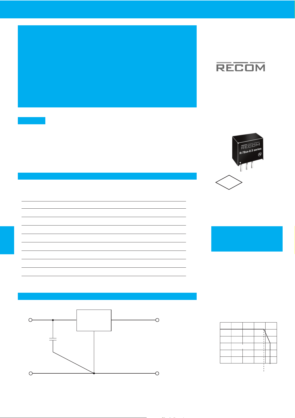
The R-78xx-Series high efficiency switching regulators are ideally suited to replace 78xx linear regulators and are pin
compatible. The efficiency of up to 97% means that very little energy is wasted as heat so there is no need for any heat
sinks with their additional space and mounting costs. Low ripple and noise figures and short circuit , overload and
over-temperature protection round off the specifications of this versatile converter series.This R-78xx-0.5 is fully
certified to EN 55022 (Emissions), and EN55024 (Immunity) EMC Standards and for EN-60950-1 Safety.
Description
EN-55022 Certified
EN-55024 Certified
EN-60950-1 Certified
R-78xx-0.5
-Vout
+Vout
+Vin
-Vin
C1
3.3µF~10µF*
* Input capacitor required if Vin>26VDC (3.3µF) or if the supply is a
battery or other low impedance source (4.7µF~10µF)
Capacitor should be electrolytic or MLCC with 1R resistor in series
Standard Application Circuit
RoHS
2011/65/EU
6/6
Page 2
R-78-0.5
www.recom-international.com I-3REV: 0/2014
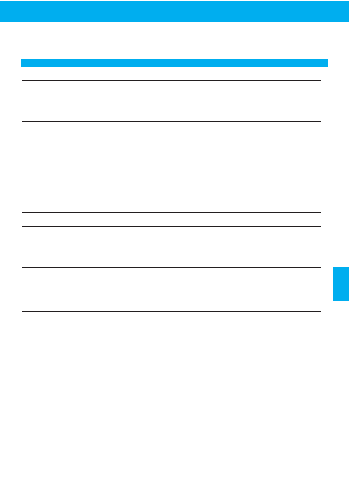
Characteristics Conditions Min. Typ. Max.
Input Voltage Range 1.5V 4.75 30V 34V abs. max.
1.8V to 15.5V 4.75 32V 34V abs. max.
Output Voltage Range (for customized parts) All Series 1.25 15.5V
Output Current (see note) All Series 0* 500mA
Output Current Limit All Series 2000mA
Short Circuit Input Current (Vin = 24V) All Series 60mA
Internal Power Dissipation 0.4W
Short Circuit Protection Continuous, automatic recovery
Output Voltage Accuracy (At 100% Load) All Series ±2 ±3%
Line Voltage Regulation (Vin = min. to max. at full load) 1.5V to 6.5V 0.2 0.4%
9V to 15.5V 0.1 0.2%
Load Regulation (10 to 100% full load) 1.5V to 6.5V 0.4 0.6%
9V to 15.5V 0.25 0.4%
Note: Operation under no load will not damage these devices, however they may not meet all specifications. A minimum load of 6mA is recommended
Dynamic Load Stability 100% <-> 50% load ±75mV
100% <-> 10% load ±100mV
Note: The R-783.3-0.5 requires Vin>5.5V to meet the Dynamic Load Stability Specification.
Ripple & Noise (without Output Capacitor) 1.5V to 6.5V 20mVp-p 30mVp-p
9V to 15.5V 30mVp-p 40mVp-p
Ripple & Noise (with Output Capacitor=100µF) 1.5V to 6.5V 15mVp-p 20mVp-p
9V to 15.5V 25mVp-p 35mVp-p
Temperature Coefficient -40°C ~ +85°C ambient 0.015%/°C
Max capacitance Load with normal start-up time, no external components 220µF
with <1 second start up time + diode protection circuit 6800µF
Switching Frequency 280 330 380kHz
Quiescent Current Vin = min. to max. at 0% load 5 7mA
Operating Temperature Range -40°C +85°C
Operating Case Temperature +100°C
Storage Temperature Range -55°C +125°C
Case Thermal Impendance 70°C / W
Thermal Shutdown Internal IC junction +160°C
Case Material Non-Conductive Black Plastic
Potting Material Epoxy (UL94V-0)
Conducted Emissions (with filter) EN55022 Class B
Radiated Emissions (with filter) EN55022 Class B
ESD EN61000-4-2 Class A
Radiated Immunity EN61000-4-3 Class A
Fast Transient EN61000-4-4 Class A
Conducted Immunity EN61000-4-6 Class A
Magnetic Field Immunity EN61000-4-8 Class A
Package Weight 1.9g
Packing Quantity 42pcs per Tube
MTBF (+25°C) using MIL-HDBK 217F 21098 x 10³ hours
(+71°C) using MIL-HDBK 217F 4212 x 10³ hours
Certifications
EN General Safety Report: SPCLVD 1301026-1 EN 60950-1:2006 + A12:2011
EMC Report: 5A111502E EN55022, EN61000, EN55024
R-78xx-0.5
Series
Specifications
( typical at 25°C, 10% minimum load, unless otherwise specified )
INNOLINE
DC/DC-Converter
}
Detailed Information see
Application Notes chapter "MTBF"
Page 3
I-4 www.recom-power.comREV: 0/2014
R-78-0.5
INNOLINE
DC/DC-Converter
Characteristics
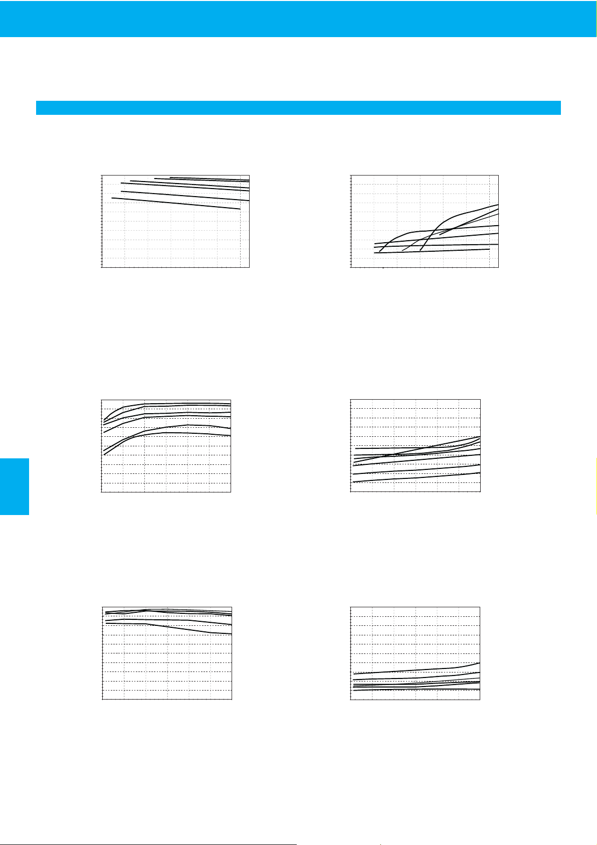
Efficiency (%)
100
20
10
Efficiency Vs
Vin (Full Load)
Vo=1.8V
Vo=3.3V
Vo=5V
Vo=9V
Vo=12V,15 V
50
Vin (V)
30
34
Vo=1.5V
Efficiency
Efficiency (%)
100
0.1
Efficiency Vs
Load ( Vin=Max )
Vo=1.8V
Vo=3.3V
Vo=5V
Vo=12V
50
Output Current ( A )
0.2
0.3
0.4
0.5
0.6
Vo=15V
Vo=1.5V
Efficiency (%)
100
0.1
Efficiency Vs
Load ( Vin=Min )
Vo=1.8V
Vo=3.3V
Vo=5V
Vo=12V,15V
50
Output Current ( A )
0.2
0.3
0.4
0.5
0.6
Vo=1.5V
Ripple (mV)
50
20
10
Ripple Vs
Vin (Full Load)
Vo=1.8V
Vo=3.3V
Vo=5V
Vo=9V
Vo=12V
25
30
Vin (V)
34
Vo=15V
Vo=1.5V
Ripple
Ripple (mV)
50
0.1
Ripple Vs
Load ( Vin=24V )
Vo=1.8V
Vo=3.3V
Vo=5V
Vo=12V
25
Output Current ( A )
0.2
0.3
0.4
0.5
0.6
Vo=9V
Vo=15V
Vo=1.5V
Ripple (mV)
50
0.1
Ripple Vs
Load ( Vin=Min )
Vo=1.8V
Vo=3.3, 9V
Vo=5V
Vo=12V
25
Output Current ( A )
0.2
0.3
0.4
0.5
0.6
Vo=15V
Vo=1.5V
R-78xx-0.5
Series
Page 4
R-78-0.5
www.recom-international.com I-5REV: 0/2014
Application Examples
INNOLINE
DC/DC-Converter
+Vin
-Vin
R-78xx-0.5
-Vout
+Vout
Com
C1 C2
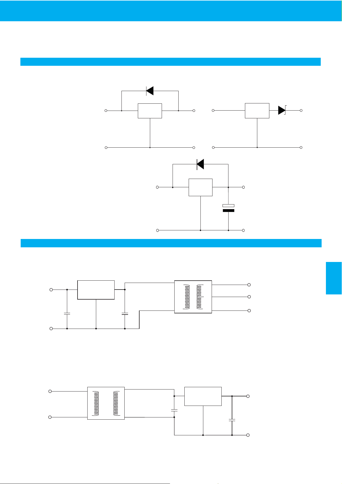
DC/DC Converter ( 1:1 )
- Isolated dual outputs
- Wide input range 4.75V to 34V
C1 , C2 : optional
+Vin
-Vin
R-78xx-1.0
-Vout
+Vout
C1
C2
DC/DC Converter ( 1:1 )
- Improved loading / line regulation
- Wide Input Voltage Range
C1 , C2 : optional
- Point-of-Load Architecture
- High isolation voltage
R-78xx-0.5
Series
High efficiency, isolated, dual unregulated outputs
Isolated (up to 6KV), wide Input range regulated output
Add a blocking diode to Vout if
current can flow backwards into
the output, as this can damage
the converter when it is powered
down.
The diode can either be fitted
across the device if the source is
low impedance or fitted in series
with the output (recommended).
Optional Diode Protection Circuit
Optional Protection 1:
Optional Protection 2:
R-78xx-xx
-Vout
+Vout
+Vin
-Vin
R-78xx-xx
-Vout
Vout=
+Vout -
0.3V
+Vin
-Vin
Schottky Diode
R-78xx-xx
-Vout
+Vout
+Vin
-Vin
6800µF
Application example:
Driving a high capacitive load
Page 5

I-6 www.recom-power.comREV: 0/2014
R-78-0.5
2.54
2.54
Top View
Bottom View
Front
7.55
2.0
0.25
5.08
3.21
213
4.10
0.51 typ.
0.7
± 0.1
10.2
RECOM
R-785.0-0.5
****
Pb
1.00ø+0.15/0
11.50
RECOM
R-785.0-0.5
****
Pb
Package Style and Pinning (mm)
SIP3 PIN Package
Pin Connections
Pin #
1 +Vin
2 GND
3 +Vout
xx.x ±0.5mm
xx.xx ±0.25mm
Recommended Footprint Details
INNOLINE
DC/DC-Converter
R-78xx-0.5
Series
The product information and specifications are subject to change without prior notice. All products are designed for non-safety critical commercial and industrial applications.
The Buyer agrees to implement safeguards that anticipate the consequences of any failures that might cause harm, loss of life and/or damage property.
 Loading...