

Page 1
User Manual
VW100
Page 2

Manual Version: 20120522.ver1.1
Publication Date: 2012 May
MUMVW0011
Page 3
1
VW100
Catalog
Disclaimer ----------------------------------------------------------------------------------------- 2
Feature ---------------------------------------------------------------------------------------------4
Product Specification --------------------------------------------------------------------------- 5
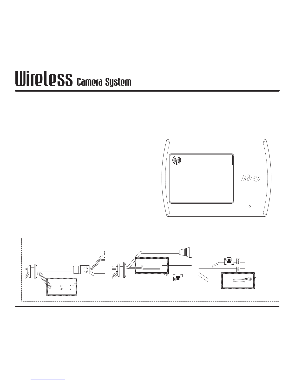
Wire connection position---------------------------------------------------------------------- 7
Installation position ----------------------------------------------------------------------------- 8
Installation method -----------------------------------------------------------------------------9
Operation ---------------------------------------------------------------------------------------- 10
Pairing -------------------------------------------------------------------------------------------- 11
Page 4
2
VW100
Disclaimer
1. Please notice operating voltage for wireless camera system. If
misconnection result in breakdown or damage, we are not going to provide
warranty.
2. If wireless camera system have been series connect to un-original
manufacture accessories and result in breakdown or damage, we are not
going to provide warranty.
3. No part of this publication may be reproduced, stored in a retrieval system,
or transmitted in any form or by any means, electronically, mechanically, by
photocopy, recording or otherwise, without the prior written permission of
REC Technology Co., Ltd.
Page 5
3
VW100
1.
This transmitter must not be co-located or operating in conjunction with any other antenna or transmitter
.
2.
This equipment complies with FCC RF radiation exposure limits ser forth for an uncontrolled environment.
This equipment should be installed and operated with a minimum distance of 20 centimeters between
the radiator and your body .
3.
This equipment has been tested and found to comply with the limits for a Class B digital device, pursuant
to part 15 of the FCC rules. These limits are designed to provide reasonable protection against harmful
interference in a residential installation. This equipment generates, uses and can radiate radio frequency
energy and, if not installed and used in accordance with the instructions, may cause harmful interference
to radio communications. However, there is no guarantee that interference will not occur in a particular
installation. If this equipment does cause harmful interference to radio or television reception, which
can be determined by turning the equipment off and on, the user is encouraged to try to correct the
interference by one or more of the following measures:
a. Reorient or relocate the receiving antenna.
b. Increase the separation between the equipment and receiver.
c. Connect the equipment into an outlet on a circuit different from that to which the receiver is
connected.
d. Consult the dealer or an experienced radio/TV technician for help.
4.
You are cautioned that changes or modifications not expressly approved by the party responsible for
compliance could void your authority to operate the equipment.
Disclaimer
Page 6
4
VW100
Feature
• 2.4G wireless digital signal transformation technology
• Cold start are less than 500ms
• Smart Hopping technology
• Strong anti-interference ability
• Operating temperature: -20~70 degree C
• Operating voltage: 9~16V
• VGA resolution video transfer
Page 7
5
VW100
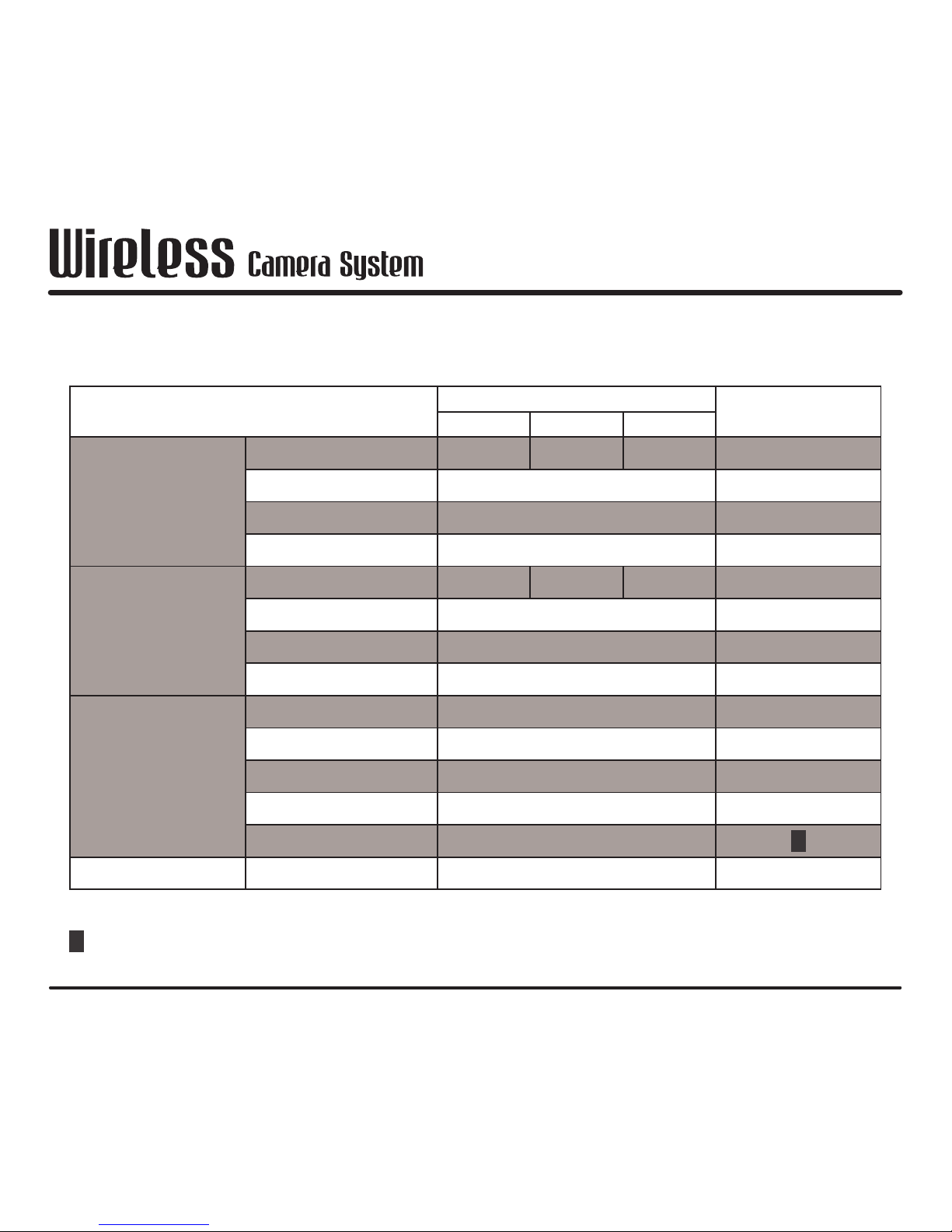
Product Specification
Item
Value
Note
Min Typical Max
Transmitter(TX)
Working voltage 9V 12V 16V
Video format MPEG4
Resolution Up to VGA @ 30fps
Power consumption < 450 mA
Receiver (RX)
Working voltage 9V 12V 16V
Power consumption < 350 mA
Monitor LCD Display
Video output NTSC
RF Section
Frequency range 2402 ~ 2478 MHz
Frequency size 2 MHz
Transmitter power 13.31 dBm
Sensitivity -79 dBm
Distance Open area up to 200m
*
Working temperature -20 ~ +70 °C
*
Transfer distance may affect by environment, weather, install angle, antenna type and more.
Page 8
6
VW100
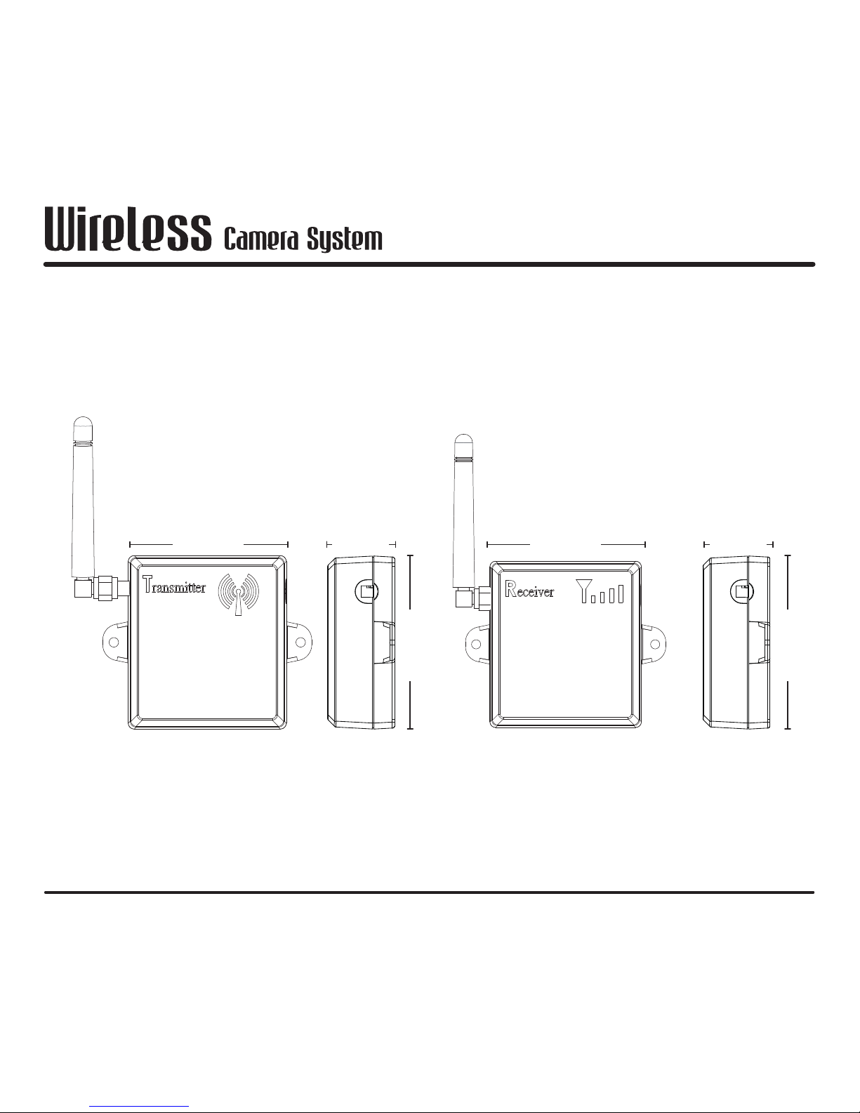
TX
RX
External antenna appearance is as followed:
66.2 66.2
72.6
72.6
28.1 28.1
Front view Front viewSide view Side view
Appearance
(External Antenna)
Page 9
7
VW100
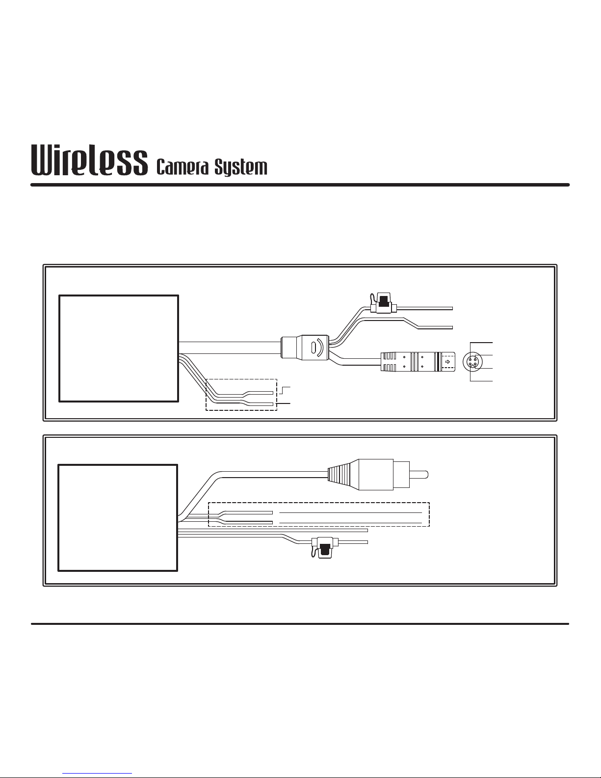
Wire connection position
Please refer to the following diagram for wire connection position
Dot line of PAIR/GND wire represent cover by heat-shrinkable tube
TX
TX
RX
RX
VIDEO OUTPUT
GND
(GREEN)
(WHITE)
GND
PAIR
GND
(BLACK)
+12V
(RED)
RCA
FUSE 2A
(GREEN)
(WHITE)
GND
PAIR
1
2
4
3
PVC Molding
Color:Green
1_+12V
2_GND
(RED)
(BLACK)
+12V
GND
VIDEO
FUSE 2A
Page 10
8
VW100
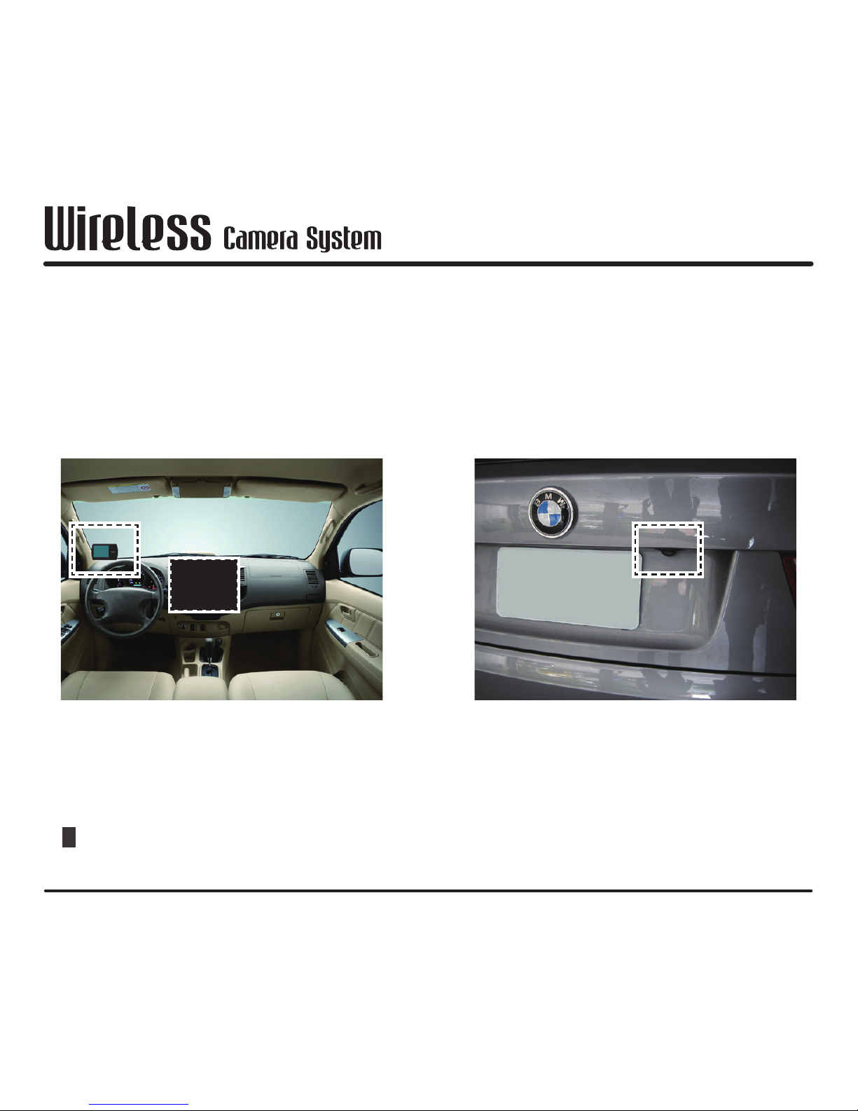
Please refer to the following diagram for installation position. TX and RX
installation position can be anywhere suitable except will affect driving safety.
Installation position
*
Part of product number are not contain vehicle monitor and backup camera,
please refer to [Product content]
Vehicle monitor installation position
Can connect to external monitor or
connect to 2-DIN monitor.
Backup camera
installation position
Page 11
9
VW100
Installation method
1. Install backup camera to proper position (if vehicle already have backup
camera, please skip to 2.)
2. Connect backup camera with TX.
3. Connect TX power to backup light's power. ( wire connection position please
refer to [Wire connection position])
4. Fix TX into proper position.
5. Connect RX power to ACC power. ( wire connection position please refer to
[Wire connection position])
6. Connect RX video signal into vehicle monitor.
7. Turn on power and wait until monitor showup than finish.
*
Connection position will be different for different vehicle monitor, please refer
to your vehicle monitor's manual.
Page 12
10
VW100
Operation
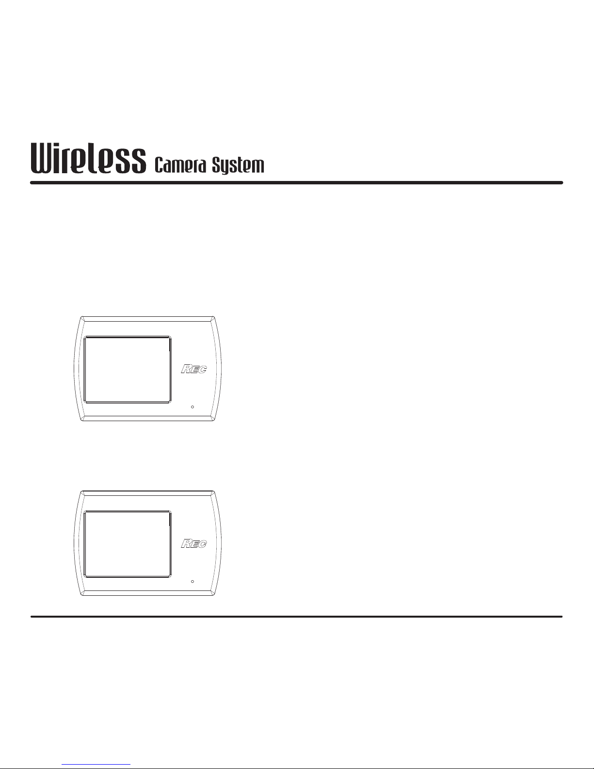
1. Monitor show nothing when car is moving or not reversing.
2. When shift into reverse gear, monitor will show up backup camera's image.
No signal
Backup
image
Page 13
11
VW100
Pairing
Our product is already pairing when first time deliver. You will need to pairing
when one of the TX/RX breakdown, damage and replace for a new one. Please
follow the following step to pairing.
1. Connect RX power into vehicle monitor
2. Take off RX and TX's heat-shrinkable tube.
3. Pull out white PAIR and green GND wire. ( please refer to [Wire connection
position] for wire definition)
4. Turn on monitor power.
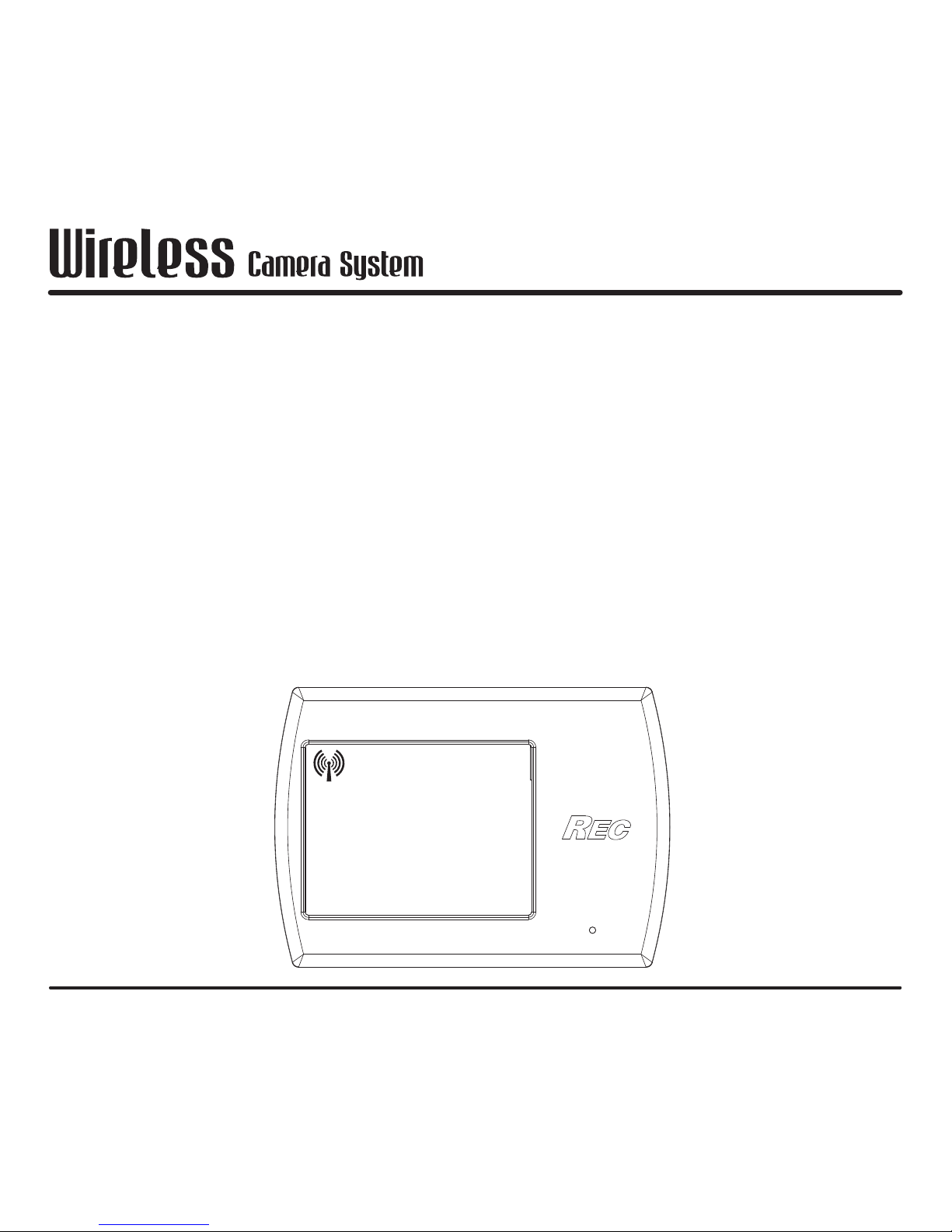
5. Monitor will show "No Signal" as followed.
No Signal
Page 14
12
VW100
VIDEO OUTPUT
GND
(GREEN)
(WHITE)
GND
PAIR
GND
(BLACK)
+12V
(RED)
S/R
RCA
FUSE 2A
(GREEN)
(WHITE)
GND
PAIR
1
2
4
3
PVC Molding
Color:Green
1_+12V
2_GND
(RED)
(BLACK)
S/R
+12V
GND
VIDEO
FUSE 2A
TX RX
Monitor
(GREEN)
(WHITE)
GND
PAIR
1_+12V
2_GND
(RED)
(BLACK)
Pairing
6. Connect RX's white PAIR and green GND wire for 3~% seconds.
7. Monitor will show " Please press paor
key on sensor side 30 sec" as right
diagram.
8. Connect TX's white PAIR and green
GND within 30 seconds (short circuit)
and wait until video show up than
finish pairing.
Please press pair key
on sensor side 30 sec
Page 15
www.rectech-global.com
 Loading...