

Page 1
BA No.: 02.07.147/2017-01
User Instructions
GB
Important!
Read the User Instructions before using the chair the first time and keep it at hand for the user.
Keep the User Instructions booklet at hand for future use and subsequent sales.
The user instructions and the maintenance manual are downloadable on our homepage.
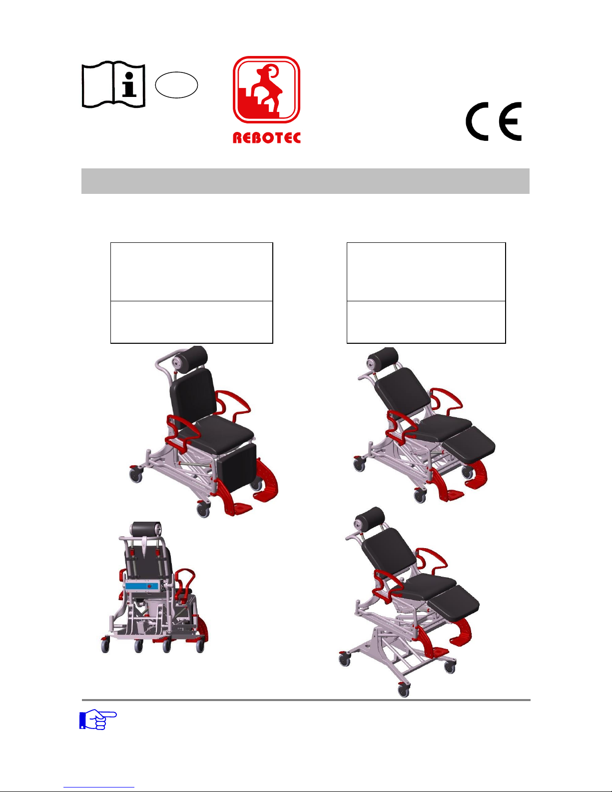
Electric Tilt & Lift Shower Chair
Phoenix Multi
Seat with hygiene opening
352.xx.10
Serial Number
Phoenix Multi
Enclosed seat
352.xx.40
Serial Number
Height adjustment
Laying position
Sitting position
REBOTEC
®
Rehabilitationsmittel GmbH
PO Box Q541
Queen Victoria Building
NSW 1230
rebotec.com.au
Page 2
REBOTEC / BA No.: 02.07.147/2017-01 GB
- 2 -
Product description
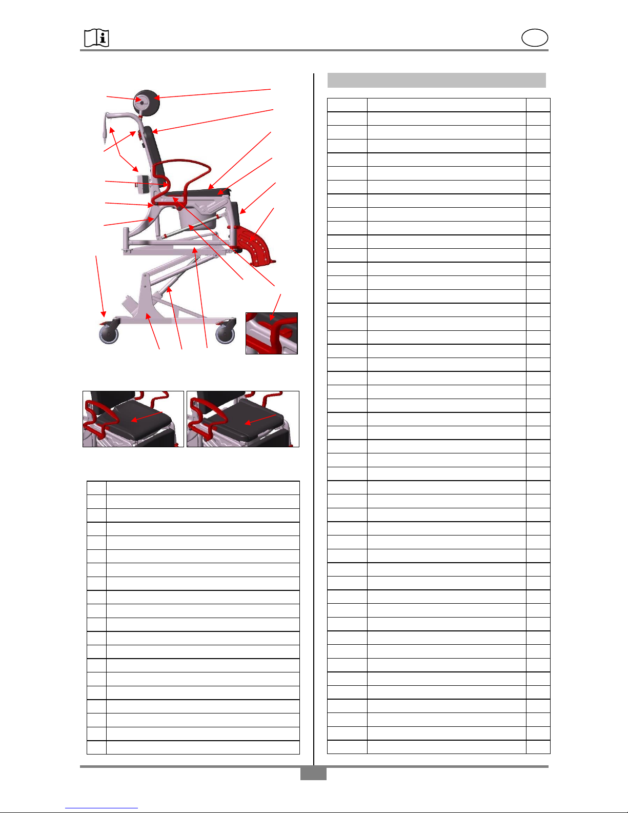
Dia 1
Seat - PS Seat PU (2-parts)
Dia. 2 Dia. 3
Chair diagram shows:
A
Rotation adjustment for PUR headrest
B
Backrest
C
Armrest (foldable)
D
Latching pins for armrest
E
Chair frame with incline adjustment
F
Castors with locking brakes
G
PUR headrest (replaceable)
H
PUR back upholstery (removable)
I
PUR seat upholstery (removable)
J
PUR seat, care opening, pan holder
K
PUR leg rest (removable)
L
Foot support with footrest (adjustable)
M
Locking lever for inclination setting
N
Toilet pan with lid (removable)
O
PUR transport seat (removable) (Dia. 2)
P
PUR seat, care opening with pad (Dia. 3)
Q
Lifting unit for seat height adjustment
R
Linear actuator
S
Control unit with hand switch
Z
Product nameplate
Table of contents
1.
General advisories
3
1.1
Introduction
3
1.2
Note LINAK mounting instructions
3
1.3
Intended proper use
3
1.4
Symbols used
3
1.5
Use and storage
3
1.6
Equipment
3
2.
Warranty
4
3.
Nameplate, ordering spare parts
4
4.
Re-use, product lifetime
4
5.
Disposal
4
6.
Safety advisories for use
4
7.
Product specifications
5
7.1
Delivery scope
5
7.2
Technical specifications
5
8.
Spare parts, accessories
6
9.
Setting up the chair for use
6
9.1
Position of the footrests
7
9.2
Adjusting the foot plate height
7
9.3
Installing, adjusting the headrest
7
9.4
Setting the inclination
7
9.5
Setting the headrest angle
8
9.6
Adjusting the seat height
8
9.7
Installing/removing the safety belt
8
10.
Electronic components
8
10.1
Battery
8
10.2
External battery charger
9
10.3
Control unit
10
10.4
EMERGENCY STOP function
10
10.5
Hand switch
10
10.6
Linear drive
11
11.
Using the chair
11
11.1
Sitting down
11
11.2
Standing up
11
11.3
Sitting and laying / low position
12
11.4
Sitting and laying while lifting
12
11.5
Using the castor locking brakes
12
11.6
Removing the seat pad
12
11.7
Folding away the footrests
12
11.8
Swiveling away the armrests
12
11.9
Removing the footrests
13
11.10
Using the commode pan
13
12.
Troubleshooting
13
13.
Care
13
14.
Maintenance and upkeep
14
14.1
Maintaining the chair
14
14.2
Maintaining electronic components
14
14.3
Upkeep
14
O
P
KB D
J
H L I
F
E
A
C
Z
M
N
S
Q
R
Page 3
REBOTEC / BA No.: 02.07.147/2017-01 GB
- 3 -
Packaging
Keep the packaging for later
transport. This will allow proper
packaging in the event of a return
shipment.
1. General advisories
1.1 Introduction
In this User Instructions booklet you will find
information and advisories for start-up, use,
operation, maintenance and care of the Phoenix
PU-E and PS-E wheelchairs.
Carefully read the User Instructions before using the
product. Abide by the safety instructions and act
accordingly.
1.2 Note LINAK-mounting instructions
The assembly instructions for the electronic drive
unit of LINAK GmbH are also applicable. The assembly instructions can be downloaded from
www.linak.de. This also makes it possible to print
out the information and read it if necessary.
The names listed in the table lead to the corresponding documents via the search function of the
website.
1.3 Intended proper use
The wheelchair is for household and out-patient
purposes. It is to be used exclusively for
assistance when going to the toilet, showering
(only with the seat cushion with hygiene opening:
model PU-E) or when transferring a person
indoors.
Rolling over a toilet is not possible!
The shower cabin should be constructed so that it
is possible to travel into it with a wheelchair. The
wheelchair is not suitable for extended periods of
sitting and for long patient transfer distances.
Persons with limited perception and senses, joint
damage in the arms, and inabilities to sit may not
use this wheelchair.
Maximum user weight is ca. 150kg
(330.69lbs).
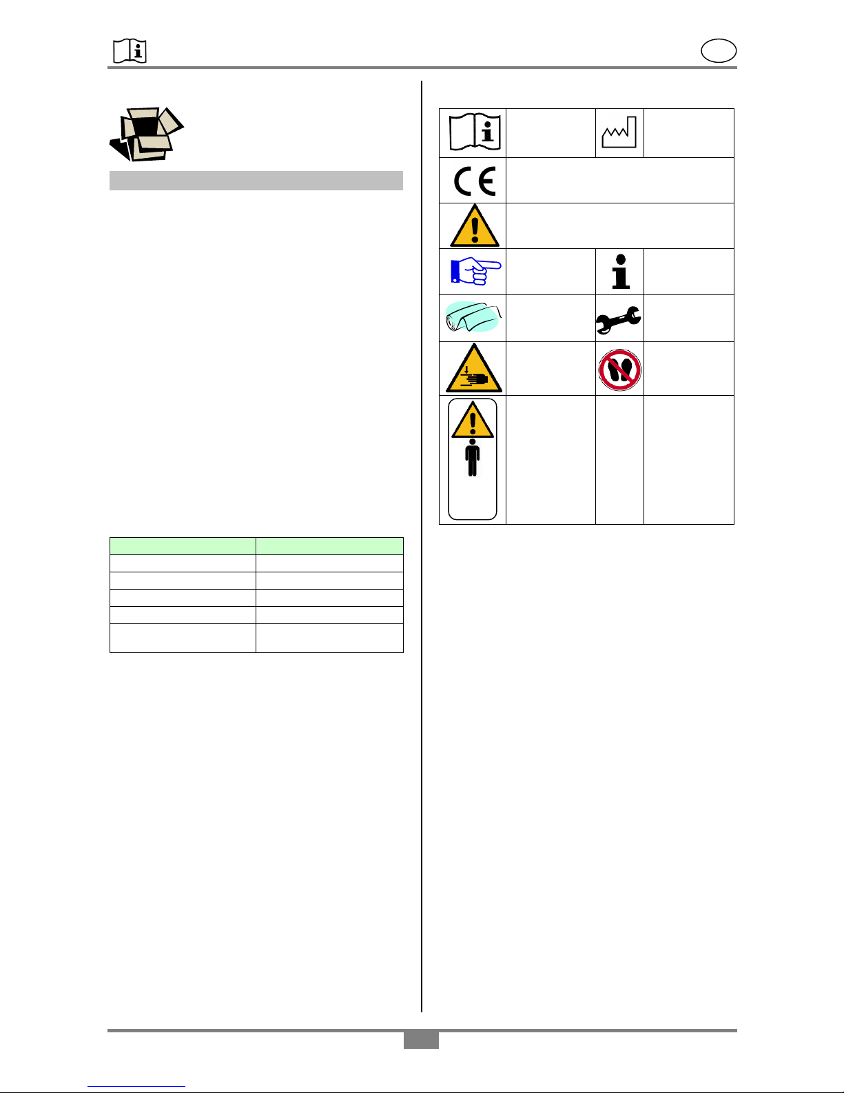
1.4 Symbols used
1.5 Use and storage
The product’s temperature range for use must be
between +41°F and +104°F. Store the product in
a dry room with a relative humidity of 30-50%. The
product may be used outside of these ranges, but
only for a short period of time.
Avoid heat sources impacting the product for
longer time periods (see safety advisory: “Caution:
danger of injury”).
The chairs may not be used in swimming pools or
sauna areas because the surface may change
colors, and limitations with respect to mechanical
stability may result.
1.6 Equipment
The chairs are made of a plastic frame, a lifting
frame made of aluminium mounted on four 5-inch
swivel castors equipped with locking brakes. The
armrests can be swiveled and have a latching
mechanism.
The footrests are height-adjustable and may be
removed or folded away. The headrests are
height-adjustable and can be rotated.
The chair’s inclination adjustment for the patient’s
back position is done by a lever unit.
With the electric lifting unit, the patient can be lifted
approx. 400mm (15.748”).
Depending on the equipment, a PUR pad is
included for transport purposes or a PUR pad with
hygiene opening (including commode pan).
Rebotec Description
LINAK Description
Linear actuator
Actuator LA31
Hand switch
Hand switch HB30
Battery
Battery module BAJ1
Control unit
Power supply CBJ2
External battery charger
External battery charger
CHJ2
Read the
instructions!
Year of
Manufacture
Product complies to the Medical
Products Directive 93/42/EEC
Caution!
Read the safety advisories
Attention!
Advisory
Important
Information!
Care
advisory
Maintenance
advisory
Danger of
hand injury
Stepping on
surface
forbidden
Caution!
Abide to
max. user
weight or
load limit
150kg
(330.69 lbs).
IPX5
IPX6
Types of
protection
See point
point 13
max.
150 kg
Page 4
REBOTEC / BA No.: 02.07.147/2017-01 GB
- 4 -
Because of the product’s design and purpose,
disassembly for transport and storing has not
been planned and is not necessary.
2. Warranty
We grant a warranty of 2 years on the product. The
warranty is valid as long as the product is used in
accordance to the operational requirements and
within the general terms and conditions stated in
this manual.
Unauthorized modifications done to the product
without the manufacturer’s permission
automatically leads to nullification of the warranty on
the product.
The delivery date written on the REBOTECdelivery note applies as the valid start date of
the warranty period.
3. Nameplate, ordering spare parts
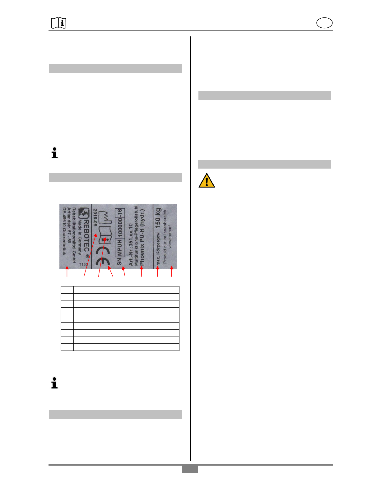
The nameplate contains the following information:
A
Symbol of conformity
B
Product serial number
C
Year of manufacture (month-year)
D
Load capability (max. body weight
330.69 lbs)
E
Product name
F
Advisory (on use)
G
Read the instruction manual
H
Manufacturer info (address)
The nameplate is important for identifying the
product and thus must not be removed.
To avoid faulty spare parts orders and for the
purpose of processing complaints, the
product’s name, serial number (SN) and year
of manufacture are needed.
4. Re-use, product lifetime
The product is designed for re-use. The re-use
(lifetime) depends on the product’s frequency of
use and the manner of use.
Before re-use, the product must be hygienically
prepared. The technical and functional safety of
the product must be checked and, if necessary, reestablished.
The expected lifetime of the wheelchair can be
up to 5 years.
The effective lifetime, however, depends on the
frequency of use, intensity of use, and its general
condition.
5. Disposal
Disposal and recycling of used products as well as
the packaging material must be done according to
the applicable rules and legal regulations. Please
contact your local disposal company or
environmental authorities for further information.
Further information can also be obtained from the
assembly instructions of LINAK. See point 1.2
6. Safety advisories for use
Abide by the following safety advisories
when using the chair:
Danger of slipping!
Before use, check to be sure the seat is firmly
mounted onto the seat frame.
Before using the chair, be sure to first lock the
castors in order to prevent the chair from rolling
away.
When sitting down, do not sit on the front seat
edge or on the pad, instead sit on the entire seat
surface.
Danger of tipping over!
The chair may be used when sitting, rolling, and
in the inclined and/or elevated position only when
the armrests are latched.
The chair may be pushed only using the push bow
(backrest).
The footrests must be swiveled away or folded up
before the patient sits down or gets up. User must
never attempt to stand on the footrests!
The chair must not bump into door sills,
thresholds or surface protrusions.
Use the chair only indoors, on solid, even and
non-slippery surfaces.
Walk only at a modest speed when pushing the
chair (with or without the patient).
Users must not lean out of the chair (when the
chair is still or in motion). If the swivel castors are
swiveled inwards, the stability of the chair is
decreased.
Use care when moving the chair (without user) in
the inclined position and/or when it is at its
maximum height!
Passenger transport may only be carried out in
the retracted position (initial position) of the chair.
Danger of pinching!
To prevent body parts, etc. from being pinched,
never reach into the hinge area when folding the
B G A D E H F
C
Page 5
REBOTEC / BA No.: 02.07.147/2017-01 GB
- 5 -
armrests up or down. See section 11.8, page 12
for more information.
To prevent body parts or objects from getting
pinched, do not reach between the seat and the
frame when pressing the pad into the seat frame
or adjusting the inclination.
Be sure other parts do not get jammed when
folding and unfolding the footrests.
When adjusting the headrest, be sure that no
body parts or objects get pinched.
There’s a risk of pinching soft flesh when pulling
out and pushing in the commode pan. To avoid
injury, the commode pan may be pulled out or
pushed in only when no one is sitting on the chair.
Danger of tipping!
When standing up, sitting and moving with the
chair, do so only when both armrests are latched
in position.
Sitting, standing up, moving, or laying in the chair
(when chair is in the inclined position) by the
patient, and lifting (height adjustment with lifting
unit) of the patient, are to be done only with the
help of a trained attendant. This depends on the
health condition of the patient.
Before and during the placement of the patient on
the chair, the patient should firmly hold on to the
armrests.
Use by patients who tend to have uncontrolled
movement and handling ability must not be done
without supervision.
Travelling on an inclined surface or ramp may be
done only with the help of an attendant. In
general an upward grade may be travelled on
while moving forwards, and a downward grade
while moving the chair backwards.
Danger of breakage!
The chair is suited only for the intended purpose.
Abide by the maximum allowable body weight
(specified on the nameplate)!
Danger of injury through temperature!
There is a risk of injury at a surface temperature
over 104°F. Therefore never keep the chair near a
strong heat source (direct sunlight. Do not store
the chair near a heat source such as a heater, or
clean it with hot water). Allow the surface of the
chair to first cool off before use.
When the chair is to be used by patients with
insensitive skin (persons who cannot feel
temperature rises and / or have skin damage),
an attendant must first check the chair for heat
(feel with the palm of the hand). Observe
Section 1.5
Safety advisory – lifting unit
Danger of pinching/crushing!
When raising or lowering the chair height, observe
the warning advisories (stickers in the area of the
lifting unit). The lifting unit in part comprises parts
that move with respect to each other and thus
present a danger of pinching or crushing when not
properly operated or used. Therefore keep hands
and feet away from these parts, and do not reach
into the lifting unit during raising and lowering the
chair.
Warning! Danger of injury!
Be sure that no third party or object is in the area
of hazard when the lifting unit is raised or lowered.
Before using the chair and the lifting unit, the chair
must be on a solid and stable surface.
Observe the maximum allowable patient body
weight, as the chair is designed only for this max.
load.
Also observe the safety instructions in the
assembly instructions of LINAK GmbH (see point
1.2)
7. Product specifications
7.1 Delivery scope
The product was checked for freedom of defects
and for completeness at the factory. After receiving
the product, check it for any damage that may have
occurred during transport and for completeness.
1 wheelchair PU-E or PS-E
1 headrest unit
1 safety belt (Art. No.: 322.30.10)
1 changeover battery
1 external battery charger
1 User Instructions
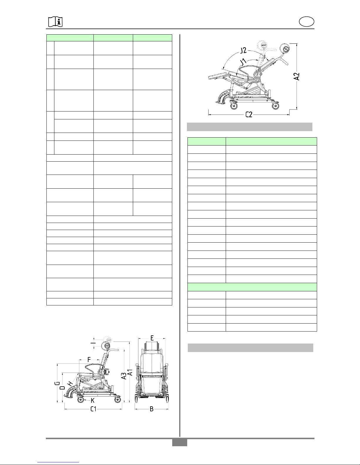
7.2. Technical specifications
For the purpose of continuous development, we
reserve the right to make modifications with respect
to the chair depicted in the User Instructions
booklet.
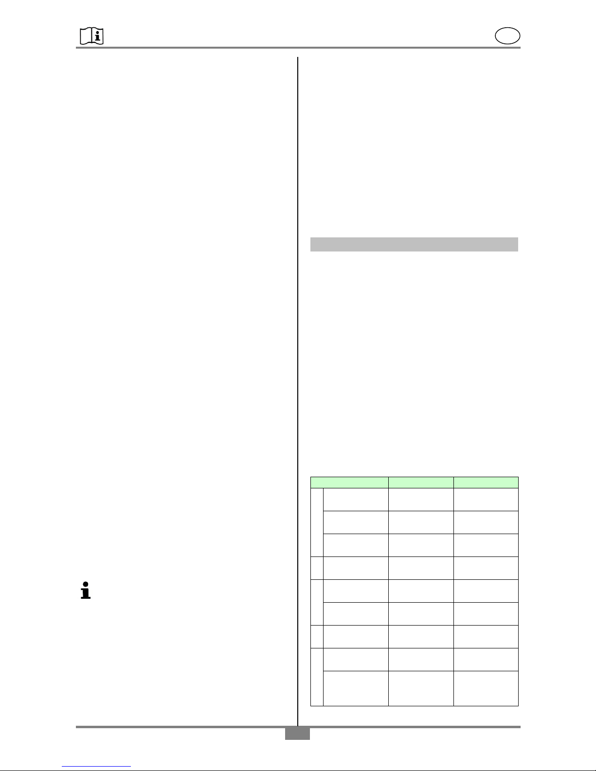
Dimension(ca.)
PU-E*
PS-E*
A
1-total height
1225mm
(48.23”)
1225mm
(48.23”)
2-total height
1180mm
(46.46”)
1180mm
(46.46”)
3-push bow
height
1065mm
(41.93”)
1065mm
(41.93”)
B
Total width
680mm
(26.77”)
680mm
(26.77”)
C
1-total depth
1165mm
(45.87”)
1165mm
(45.87”)
2-total depth
1435mm
(56.50”)
1435mm
(56.50”)
D
Seat height
600mm
(23.62”)
590mm
(23.23”)
E
Seat width
450mm
(17.72”)
450mm
(17.72”)
Width
between
armrests
540mm
(21.26”)
540mm
(21.26”)
Page 6
REBOTEC / BA No.: 02.07.147/2017-01 GB
- 6 -
Dimension(ca.)
PU-E*
PS-E*
F
Seat depth
440mm
(17.32”)
430mm
(16.93”)
G
Armrest
height
785mm
(30.91”)
785mm
(30.91”)
H
Footrest
height
440-520mm
(17.32-
20.47”)
430-510mm
(16.93-
20.08”)
I
Height
extension of
head rest
120mm
(4.72”)
120mm
(4.72”)
J
1-seat angle
103°
103°
2-laying
angle
128°
128°
K
Castors Ø
125mm (5“)
125mm (5“)
Lift height
ca. 400mm
(15.75”)
ca. 400mm
(15.75”)
Lifting unit
stepless
Duty cycle
2min. operation, 18min.
pause
Turn radius
1250mm
(49.21”)
1250mm
(49.21”)
Body weight
max. 150kg
(330.69 lbs)
max. 150kg
(330.69 lbs)
Chair weight
53,6kg
(118.20lbs)
53,0kg
(116.85lbs)
Lifting cycles
App.45 / battery charge
Linear actuator
IPX6
Battery
IPX5
Hand switch
IPX6
Control unit
IPX5
Ext. battery
charger
IPX5
Safety
Safety protection class I
Emergency stop function
Power supply
External battery charger
100-240V AC
Skin compatibility
As to DIN EN 10993-5
Inflammability
As to DIN EN 1021-2 **
* Dimensions for model w/ head rest roller, Design 1
**Flame-retardant: article made of PUR material
Production dimensional tolerances: +/- 5 mm (0.2”)
Schematic:
8. Spare parts, accessories
Article No.
name
440.10.62
PUR seat pad *
440.10.04
PUR care seat with care opening*
309.10
Pan holder, black*
440.10.24
PUR care seat w/o care opening*
450.10.16
PUR back upholstery
450.10.17
PUR leg pad
450.00.18
PUR headrest roll, Form 1
301.xx
Commode pan with lid*
02.07.146
User Instructions Phoenix-E
02.11.151
Maintenance Instructions
322.30.20
Safety belt (size: M/L)
322.10.50
Upholstery for safety belt
422.00.80
Linear actuator
422.00.84
Hand switch
422.00.86
Battery, 2x
422.00.82
Control unit
422.00.89
External battery charger
accessories
450.00.19
PUR headrest roll, Form 2
440.10.32
PUR armrest cushion (1 pc.)
440.10.40
PUR spray protection (1 pc)
322.30.10
Leg belt (size S)
322.30.99
Set: safety belt and upholstery
* Depends on the equipment variant, PU or PS
9. Setting up the wheelchair for use
The product is delivered completely assembled in a
carton. Before using the first time, the wheelchair
first must be checked over for transport damage.
Settings and adjustments may be done only by a
qualified specialist. Before using the batteries for
the first time, they must be charged for 24 hours to
ensure proper operation and lifetime.
Page 7
REBOTEC / BA No.: 02.07.147/2017-01 GB
- 7 -
Caution!
All cables must be routed in such a way, preventing
people from stumbling, and causing injury during
use. It is important to remove the plastic foil from the
cables before use.
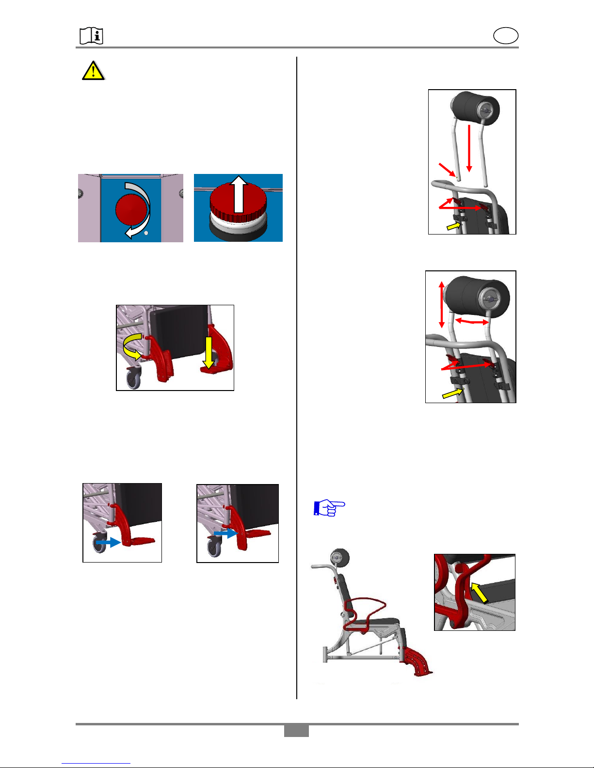
The emergency-stop button may have to be
deactivated before operating. Turn the knob
clockwise (arrow direction) until it is unlocked.
9.1 Position of the footrests
Rotate the footrests (1) all the way to the front until
they latch in position. Next unfold the foot plates
(2).
The foot plates may need to be height adjusted.
9.2 Adjusting the foot plate height
The foot plates are height-adjustable to four
positions. Remove the screws from the side at the
footrests using an SW 5 Allen key. Select the
appropriate level (1-4) and once again tighten the
screws at the foot plates.
Be sure that the screws are firm!
9.3 Installing, adjusting the headrest
Installation:
Flip the levers (A) upwards
and insert the tubes of the
headrest unit into the
openings.
Push the tubes down until
the push-buttons (C) click
in the holes (D).
Next push the button (C)
all the way in and push the
tube to the end and press
the levers (A) all the way
down.
Setting the height and
depth:
To set the headrest height, flip both levers (A)
upwards and push the head rest to the appropriate
height.
The head rest can be
steplessly adjusted (ca.
120mm / 4.72”) until the
button (D) clicks into the
hole (end-position).
After setting, press both
levers (A) down again. By
removing the clips (C), the
headrests can be removed
for cleaning or for
replacing.
9.4 Setting the inclination
The backrest may be steplessly inclined back up to
approx. 37°. Here the seat inclines up to 12°. Next
pull the locking levers (A) vertically upward and
push the backrest (B) downward until the desired
position is reached. Next press the locking levers
(C) all the way down.
When adjusting the backrest inclination,
be sure that no body parts or objects get
pinched and that the armrests are latched
in position!
sitting
position
up
A
D
A
C 1 2
min
max
A
C
B
D
Page 8
REBOTEC / BA No.: 02.07.147/2017-01 GB
- 8 -
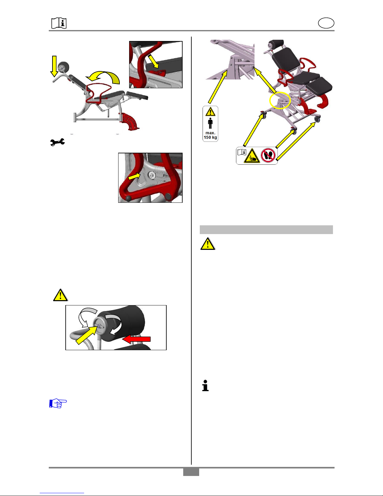
Maintenance advisories
If the function of the
locking lever becomes
difficult or too easy, then
the clamping effect can
be regulated by an
adjustment maneuver.
Remove the cap. Using
an SW 5 Allen key, the clamping force is increased
by rotating to the right, or reduced by rotating to the
left. After adjusting, check the lever function for
ease of motion.
Finally press the cap back on and latch the armrest
back into position.
9.5 Setting the headrest angle
By rotating knob (A), the headrest angle can be
adjusted.
Warning! Danger of pinching (B) between
the headrest and backrest!
9.6 Adjusting the seat height
The chair’s seat height is stepless adjustable via the
electric unit. The patient can be lifted a maximum of
400mm (15.75”).
Adhere to the warning signs!
9.7 Installing/removing the safety belt
The safety belt is already installed when the chair is
delivered. To remove it, fold away the armrests, as
described in Section 11.8 on page 12, and pull the
loops down from the armrest locking mechanism.
When re-installing, be sure the safety belt is not
twisted.
10. Electronic components
Observe safety instructions
Check whether the connection cable or the plug is
damaged. Do not use damaged cables or plugs!
Observe the main connection voltage (100-
240V / 50Hz) and appropriate main fuse for the
charger.
The control unit and the battery unit must never be
opened.
Do not operate the chair during the charging
process!
10.1 Battery
Two batteries are included. They are already preloaded. Before using the batteries, they must be
charged for 24 hours in the external charger. If the
lifting / lowering process of the chair slows down
noticeably, the battery capacity is too low.
Charge the discharged battery as soon as
possible! This increases the battery life. Longer
time unused batteries should be recharged
every 3 months to avoid deep discharges, as
this will damage the battery. For information on
durability, see 14.2.
B
laying position
A
C
down
Page 9
REBOTEC / BA No.: 02.07.147/2017-01 GB
- 9 -
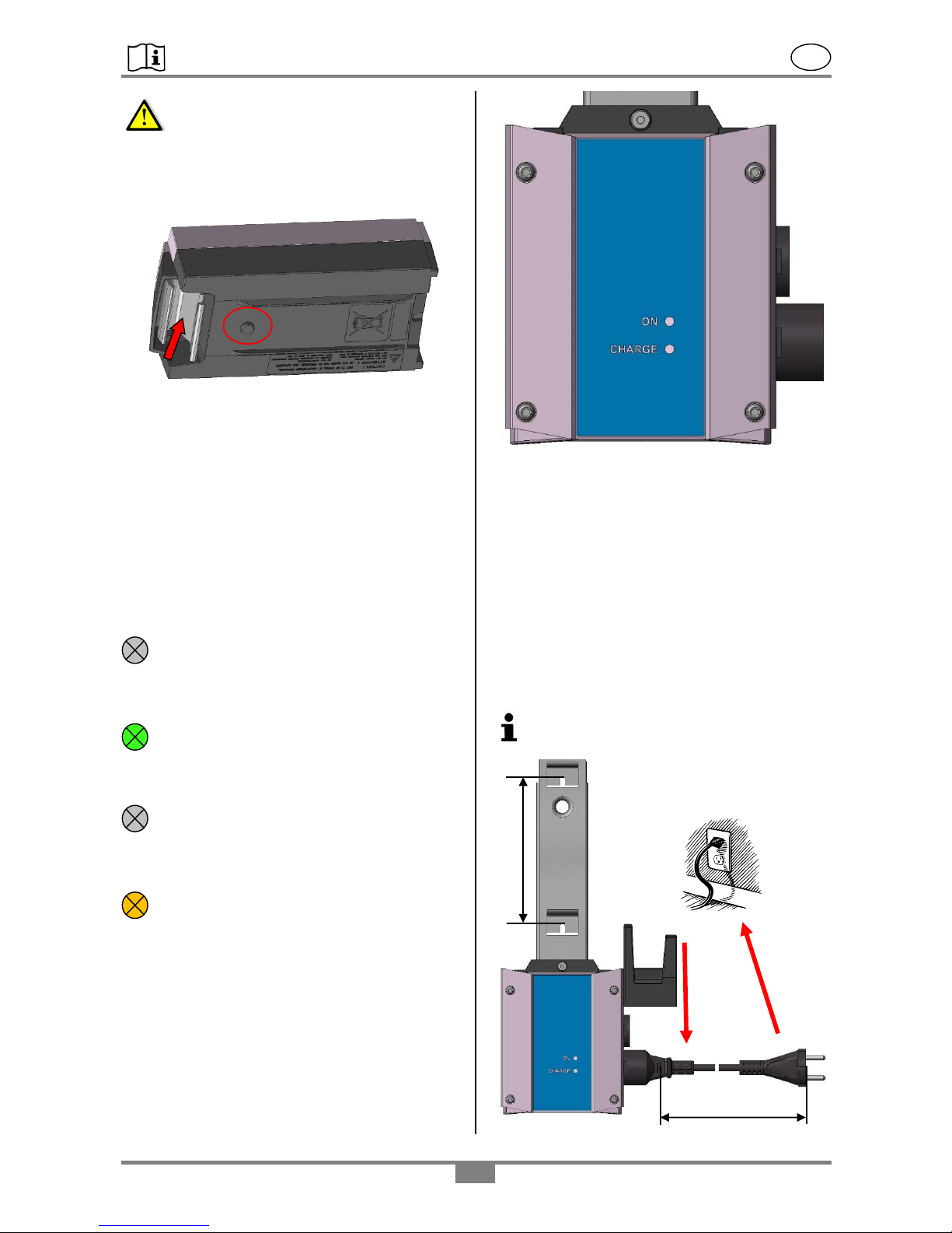
Attention!
Periodically check that the ventilation hole (A) is
working properly. Due to the construction of the
ventilation line, batteries can leak, but water can not
penetrate.
The battery is removable for charging or
replacement. For this purpose the batteries are
equipped with a snap closure (B).
Make sure that the snap lock is engaged before you
release the battery.
10.2 External battery charger
The included external charger is equipped with two
LEDs. These indicate the charge state and the
power supply.
Display
LED 1 “ON“- not illuminated:
The mains cable is not plugged into the
socket. No power supply.
LED 1 “ON“- green:
If the LED "green" lights up, the wall charger
is ready for operation.
LED 2 “CHARGE“ not illuminated:
No battery in the charger or the battery is fully
charged.
LED 2 “CHARGE“- orange:
If the LED "orange" lights up, the external
charger charges the battery.
Mounting external charger
The wall charger is attached vertically to the 2
grooves in the mounting plate of the charger. The
drilling distance is 140mm (5.51”). Make sure you
choose the right screw connection according to the
wall constitution.
Ensure that no cables lying in the wall are damaged
during assembly. REBOTEC shall not be liable for
any damage resulting from the attachment of the
charger. Make sure that the length of the main cable
(approx. 118”) is sufficient.
The weight of the external charger and battery
is about 4kg (8.82lbs)
1
2
A
A
5.51“
140mm
Ca. 3000mm
(118“)
Page 10
REBOTEC / BA No.: 02.07.147/2017-01 GB
- 10 -
The external charger has a power of 1.3 watts
in idle mode (without charging a battery). To
save power, unplug the power cord after each
charging operation.
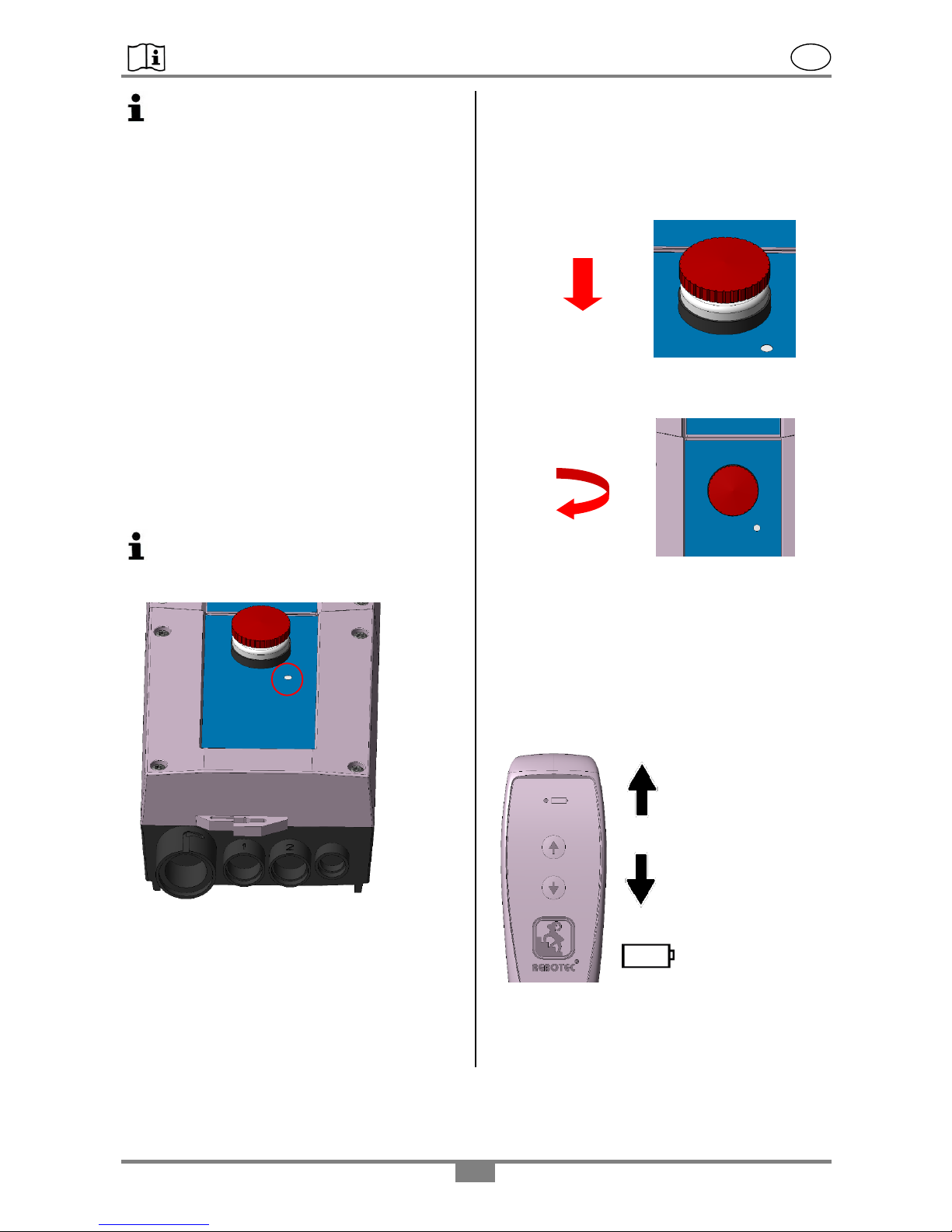
After installing the charger, slide the cap (A) over
the cable. The external charger is now ready for
use.
The charging process can take up to 4 hours
depending on the charge state of the batteries. The
duration of the charging process depends on the
main supply voltage. If the charging process takes
longer than 6 hours (at 230V main connection), the
battery or the wall charger is defective.
10.3 Control unit
The control unit is equipped with an emergency stop
function (A) and an electrical emergency lowering.
In case of emergency, the system can be switched
off the emergency stop and the linear drive can be
retracted without a hand switch. To use the
emergency lowering, use a stylus (for example a
ballpoint pen) to press the button in area B.
In order to ensure the protection class (IPX5 &
IPX6), all electrical components must be
installed with each other and none of the
connections (C) must be open.
When connecting the manual switch, make sure
that the female connector D (groove and
arrangement of the contacts) is closed so as to
avoid a defect on the control unit.
10.4 EMERGENCY STOP function
Pressing the red EMERGENCY STOP button locks
the motor. The drive is interrupted and can no longer
be controlled with the hand switch. Please use in
emergency situations and if the proper operation of
the chair is disturbed.
By turning the emergency stop head clockwise, it
jumps out and is unlocked. The drive can be
controlled again via the hand switch.
10.5 Hand switch
The drive is activated with the hand switch (infinitely
variable adjustment) and causes a "lifting" and
"lowering" of the chair.
The switch must be pressed during the respective
operation. When the switch is released, the drive
stops. When the upper or lower end position is
reached, the system stops automatically.
The control light (LED) on the top of the hand switch
provides information on the charge status of the
batteries.
Raise
Lower
Stop
Start
Control light
(LED) battery
C B A
D
Page 11
REBOTEC / BA No.: 02.07.147/2017-01 GB
- 11 -
Display
LED-off:
Battery capacity sufficient.
LED-orange:
If the LED "orange" lights up when the
handset is actuated, the battery capacity is
too low.
Battery must be charged soon!
Signal tone
In addition to the indicator light on the hand switch,
a beep sounds when the battery capacity is too low.
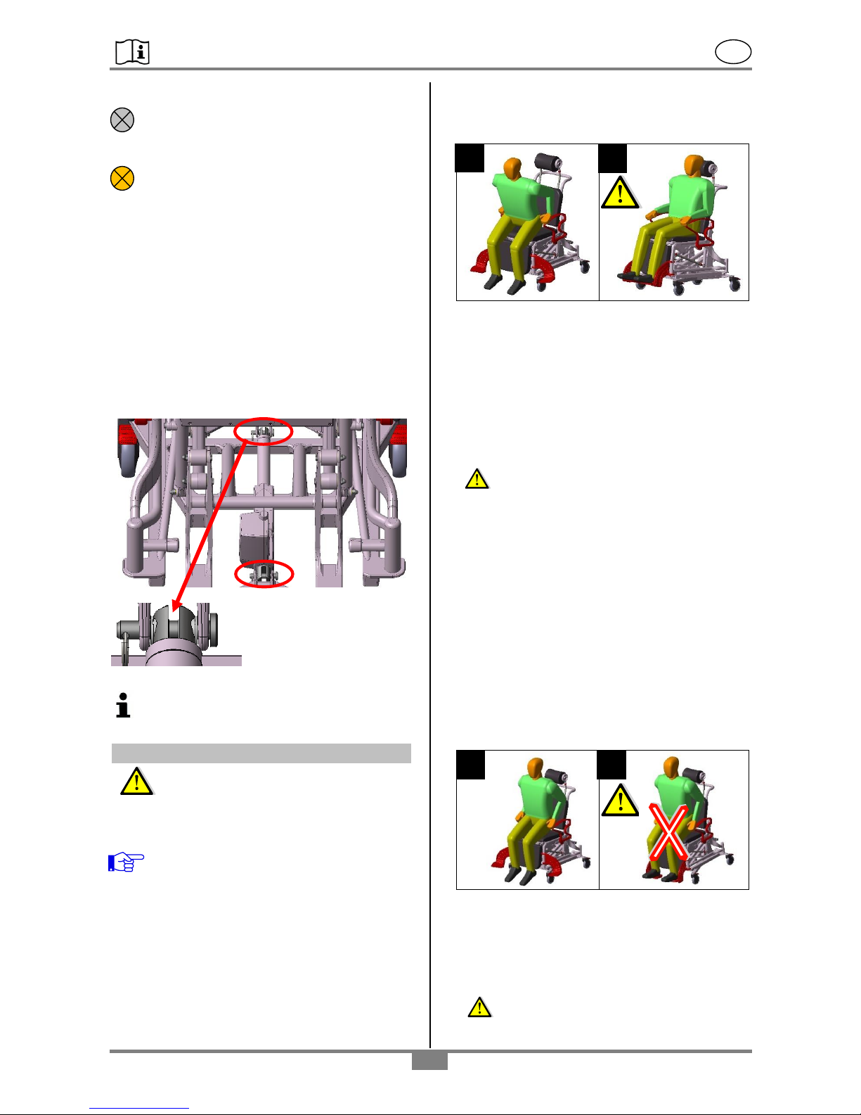
10.6 Linear drive
The linear drive generates a sound level of 48 dB in
the no-load condition. It is connected to the frame at
two points (A & B) with bolt and key ring.
Further information on the electrical system
can be found in the assembly manual of
LINAK. See point 1.2
11. Using the chair
Clean the chair before first-time use!
It must be ensured that the chair is in a proper and
safe condition before use.
If necessary, depending on the patient’s
limitations (adequate mobility and muscle
strength), sitting down and standing up may
be done only with the assistance of an
attendant. Subsequent adjustments may be
carried out only by a specialist!
11.1 Sitting down
Before sitting down it must be assured that the chair
is stable and secured against slipping away and
unfolding. At least 2 castors must be locked and
both armrests must be securely latched in position.
Also the seat must be properly in place and the foot
plates must be moved to the side or folded up.
1- The patient must be positioned as near to the
chair as possible. By firmly holding on to the
armrests, the patient must then slowly sit down onto
the seat. If this is not possible due to physical
limitations, then the patient must be assisted by an
attendant.
In the event support cannot be sufficiently provided,
then it is necessary to use lift equipment, or a patient
lifter.
2- Danger of falling!
Dropping onto the chair seat must be avoided. The
patient must sit as much as possible over the entire
seat surface, and not only on the seat edge.
When transporting a person, the surface of the seat
and the backrest must be used as much as possible.
11.2 Standing up
Before standing up, it must be certain that the chair
is stable and secured against slipping away or
tipping over. At least two wheels must be locked,
both armrests must be latched in position, the
footrests swiveled to the side or folded up, and the
patient must be sitting vertically (inclination setting
and the chair at the lowest position).
The patient must move forward on the seat surface
until the feet are flat on the floor.
3 - By supporting him/herself firmly on the armrests,
the patient must then slowly get up from the chair.
The patient must not lean too far forward in order to
avoid the risk of falling down.
The patient should seek the assistance of an
attendant whenever standing up.
4- Danger of falling!
When sitting down or standing up (leaving the
chair), the patient must never stand on the footrests!
1 2 3
4
A
B
Page 12
REBOTEC / BA No.: 02.07.147/2017-01 GB
- 12 -
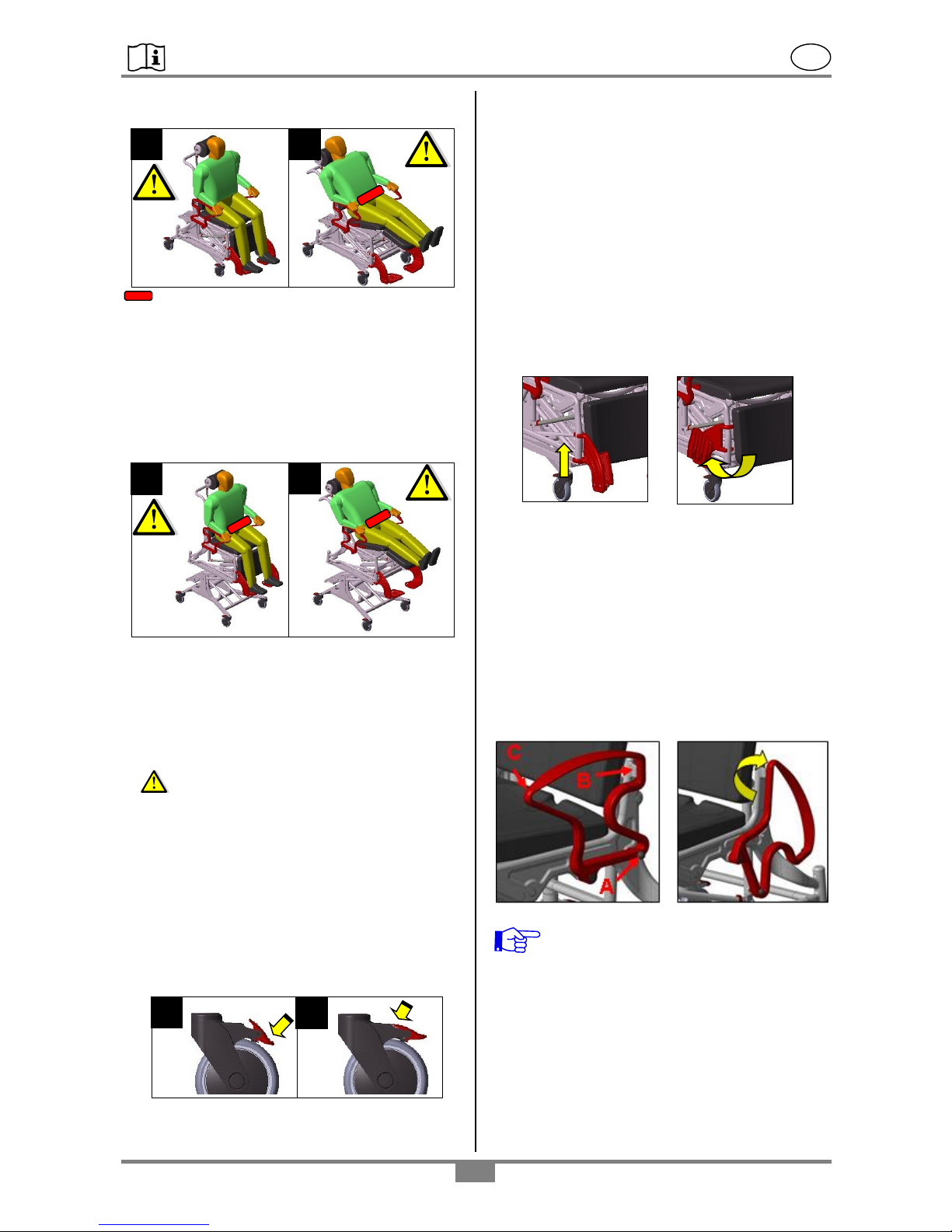
11.3 Sitting and laying / low position
Safety belt (322.30.10)
5&6 When changing the inclination angle, the
safety belt first must be used (see Section 9.7 on
page 8). At least two castor brakes must be
engaged (locked) beforehand (Section 11.5,
Schematic 1).
11.4 Sitting and laying while lifting
7&8 Should the patient be lifted by the lift
mechanism, at least two castor brakes must first be
engaged (Section 11.5, Schematic 1). The safety
belt must be fastened while the patient is sitting and
laying in order to improve the safety. Be sure that
the clamping lever for the inclination setting is
locked before the lifting begins.
Danger of tipping over!
The inclination must not be extended when the
chair is completely elevated as there is a danger
of tipping over.
• The patient must not remain unattended in the
chair at any time.
• It is not permissible to drive the chair in the lifted
position, with the patient, for safety reasons! Make
sure that the chair is in the lower position before
you release the brakes.
11.5 Using the castor locking brakes
1-Press the lever of the castor brake downward with
your foot (1). The wheel is now braked and the
castor locked against swiveling.
2-The wheel and castor are released by pressing
the lever upwards with your foot (2).
11.6 Removing the seat pad
The seat with (I) and without (O) hygiene opening,
the leg pad (K) and the backrest upholstery (H) can
be removed from their mountings in the chair frame
for cleaning purposes or for replacing (see
description on page 2).
11.7 Folding away the footrests
Flip the foot plates upwards and then lift the
footrests from the locking mechanism. The footrests
may now be folded back.
11.8 Swiveling away the armrests
By pulling out the latching pins (A) the locking effect
is disengaged and the armrests may be swiveled
back. Whenever swiveling the armrests back, check
to be sure that they are fully and properly latched in
the mounting mechanism of the backrest (B) and
that the latching pins (A) are engaged. Swiveling the
armrests is done with both hands. Keep the locking
pins (A) pulled out during the entire swivel action,
and move the armrest at point C with the other hand.
While doing so, touch only the outside surfaces and
do not grab into the armrest or through it.
Check the latching mechanism on a regular
basis because possible caking up of
calcium deposits at the latching area can
adversely effect its function and its ability to
move properly.
1
2
7 8 5
6
Page 13
REBOTEC / BA No.: 02.07.147/2017-01 GB
- 13 -
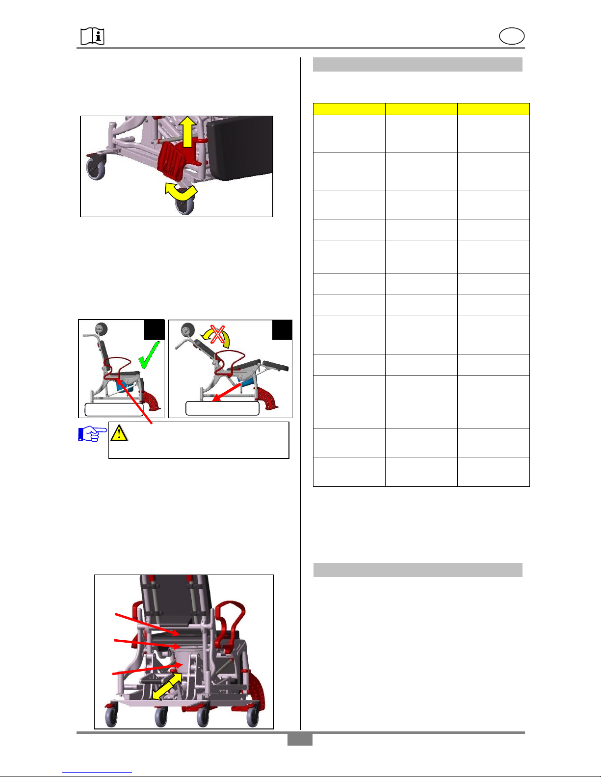
11.9 Removing the footrests
Lift the footrests approx. 100mm (3.94”) and rotate
them outward 90°. Now you are able to push the
footrests all the way up and to pull them out.
11.10 Using the commode pan
When using the chair (PU) with a commode pan, it
must be used only in the sitting position (1) and not
in the laying position (2) because the commode pan
will slide out!
Abide by the advisory sticker on the chair’s side
frame near the armrest.
How to use
Push in the commode pan (A) from the behind the
chair, by first removing the lid (B) under the seat. To
remove, lift the commode pan slightly and then pull
it out.
The armrests must be latched in position in order to
prevent the patient from falling off. After removing
the commode pan, the seat pad (C) must be put
back on the shower seat.
12. Troubleshooting
Chair malfunctions/faults
Fault
Possible cause
Remedy
Armrests
cannot be
swiveled out
Caking up in the
latching
(latching pins)
Clean, check
regularly
Latching pins
cannot be
pulled out
Caking up,
spring is
jammed or
defective
Clean,
replace the pins
Foot plate
cannot be
swiveled
Caking in joint,
jammed
Clean,
check screws
Castor brakes
do not work
Generally
defective
See
maintenance!
Castor wheels
turn with
difficulty
Caked, gummed
up
Clean
Castor wheels
do not turn
Generally
defective
See
maintenance!
Wheels wobble
Uneven profile
wear
See
maintenance!
Chair frame
unstable
Screws are
loose
Tighten screws
for castors,
frame
Castor is bent
Crashed against
obstacle
See
maintenance!
Inclination
adjustment
lever has no
function
Jammed,
breakage,
caking, screws
are too loose or
tight.
Check,
maintenance
Inclination
adjustment has
no function
Function
defective
Check,
maintenance
Headrest
adjustment has
no function
Function
defective
Check,
maintenance
Malfunctions/faults – drive unit
Please refer to the assembly instructions for LINAK
GmbH for information on faults and troubleshooting.
See point 1.2.
13. Care
The chair must not be cleaned with a steam
cleaner or cleaning machine.
Connecting cables must be plugged in during
cleaning in order to prevent the ingress of water.
Unused inputs are sealed with a plug, which must
not be removed.
Make sure that the plugs and cables are not bent
during cleaning.
In general the wheelchair can be cleaned using a
mild conventional cleaning and disinfecting agent.
Next simply wipe the chair with clean water and
cloth, and then wipe dry with a clean cloth.
Attention! Remove the commode
pan before inclining the chair to
A
C
B
1
2
Page 14
REBOTEC / BA No.: 02.07.147/2017-01 GB
- 14 -
Do not use an abrasive scouring agent or cleaner
(read the product instructions!) that contain
aggressive solvents (acids, benzene, thinners,
alcohol).
Do not use stiff cleaning objects (e.g. brushes), as
these will damage the plastic surfaces or cause
deposits to build up on the plastic parts and other
materials.
Attention! Before any cleaning, press the
emergency stop switch.
Protection
class
Cleaning instructions
IPX5
Washable with water and brush but
without running water or immersion
bath.
IPX6
Washable with water and brush.
Water can be used with pressure.
The system must not be exposed
directly to the high-pressure cleaner
jet. Max 20°C (68° F).
Keep the product clean, and clean it on a regular
basis. Hygiene must be monitored carefully,
especially in sensitive areas.
In order to ensure the protection class (IPX5 &
IPX6), all electrical components must be
installed with each other and none of the
connections (C) must be open.
14. Maintenance and upkeep
The cause of accidents or damage may be traced
back to a late detection of wear and/or improper
use, as well as irregular maintenance and upkeep.
For safety reasons and for preventing
accidents, the chair must undergo a
complete maintenance at least once a
year (refer to the Medical Products Act and
local requirements).
14.1 Maintaining the chair
Regular safety-technical checks are necessary:
The product for visible damage (cracks,
fractures, loose parts, instability).
All screwed connections for tightness (especially
the castor wheels and frame).
Function of the armrests and latching pins.
Function of the footrests (replace defective foot
plates).
Rolling ability, check function of the wheels
(replace defective wheels).
Function of the castor locking brakes (replace
defective brakes).
Function of the headrest.
Function of the chair inclination.
Check accessories for inadequacies.
In the event of any inadequacies, do not put the
product to use and do not carry out any repairs
on your own.
Contact an authorized dealership or REBOTEC.
14.2 Maintenance electronic components
Regular safety checks are required:
Check the wiring
Check the charge level before each
commissioning
Regularly check the ventilation openings in the
batteries.
Charge the battery modules regularly.
The batteries have a lifetime of 4 years depending
on the intensity of use and the general handling.
In the case of inconsistencies, do not operate the
unit and do not perform repairs on your own.
Please contact your dealer or REBOTEC.
Warning: There is a danger of injury from
slipping and pinching!
14.3 Upkeep
If you have questions concerning maintenance
and repairs to the chair, then contact an
authorized dealer or medical equipment supply
outlet.
In the event of damage and/or needed repairs,
contact the authorized dealership without delay.
Never make any unauthorized modifications or
conversions to the chair or the electric system.
These will adversely affect the safety and
function of the chair.
When making repairs, use only original spare
parts from REBOTEC and LINAK. Observe all
advisories concerning guarantee and warranty.
Once a complete maintenance or repair of the
chair is done, carry out a complete cleaning for
assuring hygiene. Follow the cleaning
instructions.
Follow the instructions for spare parts ordering,
re-use, and lifetime.
For documenting maintenance and repairs,
REBOTEC offers a maintenance protocol.
You may order User Instructions and
maintenance protocol forms, or view them at
www.rebotec.com.au
Page 15
REBOTEC / BA No.: 02.07.147/2017-01 GB
- 15 -
Page 16

REBOTEC / BA No.: 02.07.147/2017-01 GB
- 16 -
Notes:
We also suppl
y
Walk ing aids
Shoulder
crutches
Show er stools
Shower and commode chairs
M
ultifunction-W heel
Chairs
Rollators
Patient lifting hoists Standing u p aids
Your REBO
TEC Team
 Loading...