

Page 1
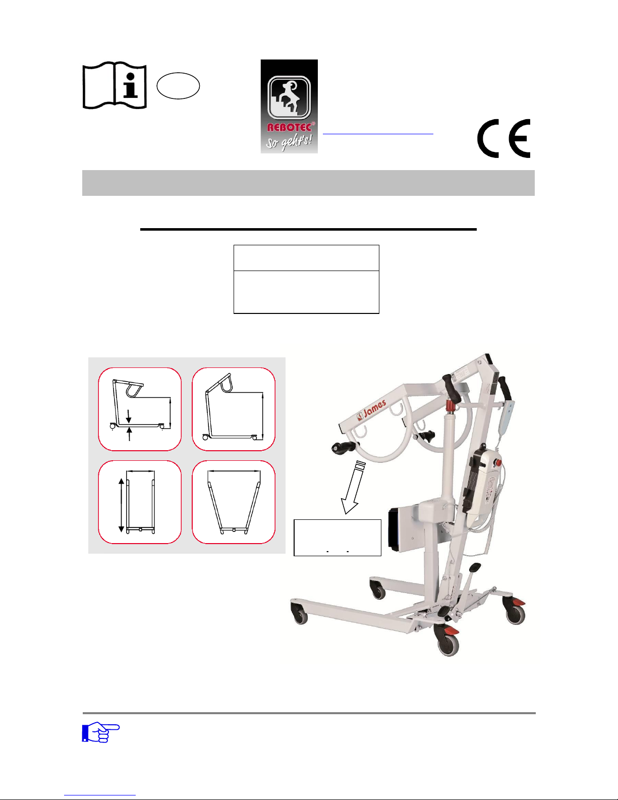
Process tolerance: +/- 2 cm
BA No.: 02.09.104/2016-12
Standing-up Hoist – James 150
User Manual
GB
Dimensions / cm
Art. No.: 320.03
Serial Number
Max. load
150 kg
Important advisories!
Read this User Manual before first time use of the Hoist and keep it at hand for the user.
Keep this User Manual booklet at hand for future use and subsequent sales.
The user instructions and the maintenance manual are downloadable on our homepage.
13
65
95
84
150
100
REBOTEC
®
Rehabilitationsmittel GmbH
DE-49610 Quakenbrück, Artlandstr. 57-59
Telephone: +49(0)5431/9416-0
Telefax: +49(0)5431/9416-66
http://www.rebotec.de
E-mail: [email protected]
Page 2
REBOTEC / BA No.: 02.09.104/2016-12 GB
- 2 -
Product description
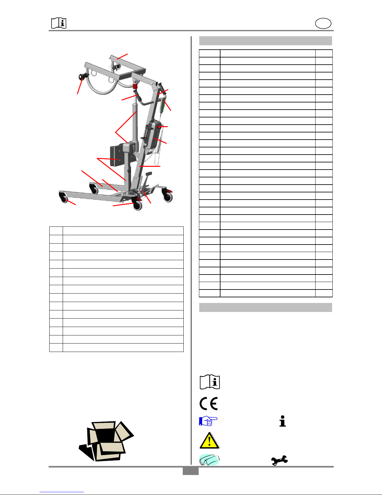
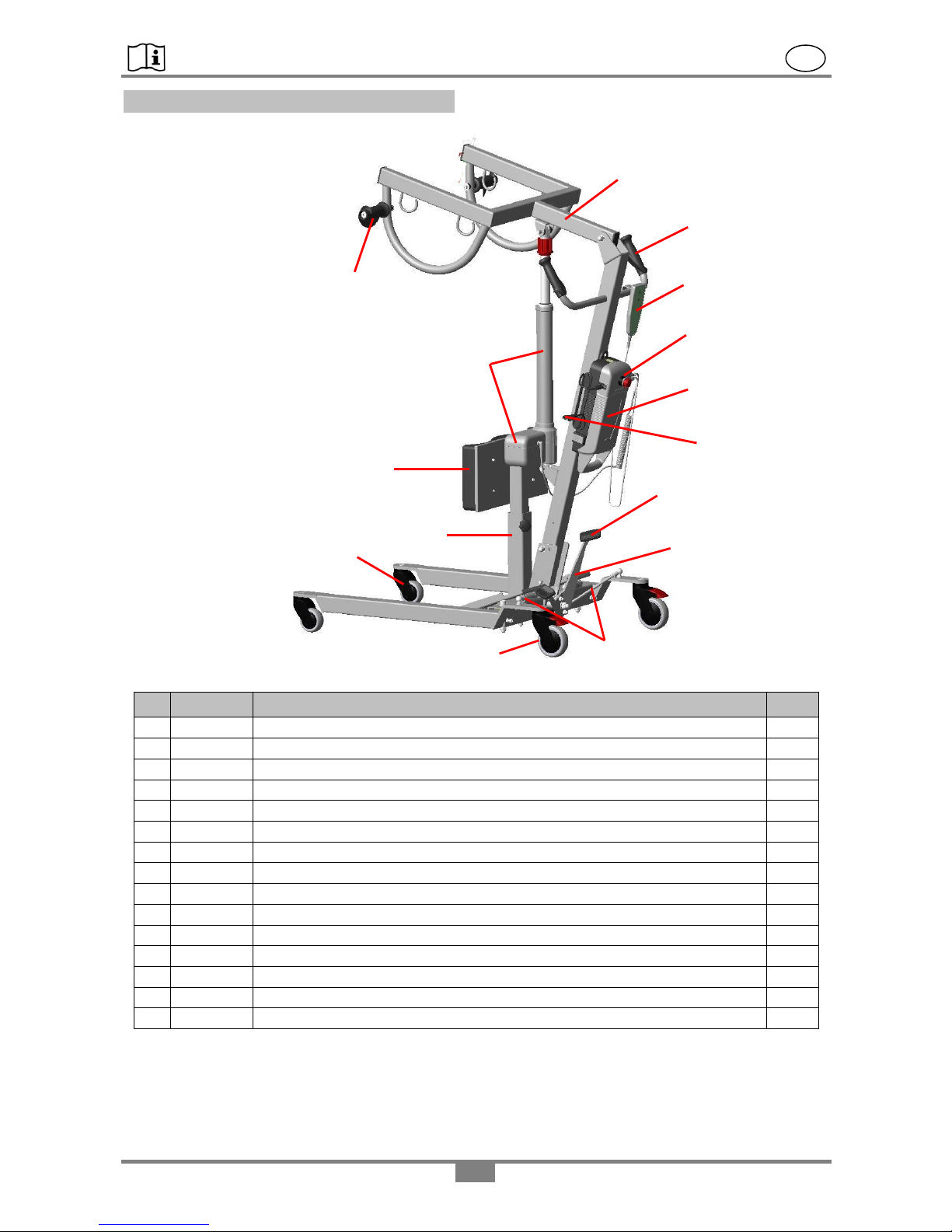
Picture shows:
A
Main Column
B
Forked arm
C
Base frame
D
Foot pedal
E
Swivel castors, front
F
Swivel castors with wheel locks
G
Front plate with anti-slip pad
H
Holder with knee protection (height-adjustable)
I
Handle bow with soft handle
J
Drive system (motor, hoisting unit)
K
Control unit
L
Hand switch
M
Rechargeable battery
N
Soft handle for forked arm (accessory)
Z
Nameplate for product (behind the column)
Packaging
We recommend you to keep the packaging for a
later transport. This will allow a secure packaging
for a return transport.
Table of contents
1.
General advisories
2
1.1
Introduction
2
1.2
Symbols
2
1.3
Intended proper use
3
1.3
Operating comfort
3
1.4
Accessories (sling)
3
2.
Warranty
3
3.
Spare parts ordering, complaints
3
4.
Re-use, lifetime
3
5.
Disposal
3
6.
Safety advisories for use
3
7.
Product specifications
4
7.1
Delivery scope
4
7.2
Technical specifications
4
8.
Accessory, Spare parts
4
9.
Setting up for use
5
10.
Charging the battery
6
10.1
Rechargeable battery
6
10.2
Connecting and charging
6
10.3
Charge level
7
10.4
Removing the rechargeable bat-
7
11.
Emergency OFF function
7
12.
Manual switch
7
13.
Wheel brakes
8
14.
Emergency lower / jam. protection
8
14.1
Electrical emergency lowering
8
14.2
Mechanical emergency lowering
8
15.
Stability – spreading the base
8
16.
Forked arm (carrier for sling)
9
17.
Troubleshooting
9
18.
Care
9
19.
Maintenance
9
20.
Spare parts
11
1. General advisories
In this manual you will find information on safe and
proper installation, use, operation, maintenance
and care of the Standing-up Hoist.
Read these operating instructions carefully before
using the product. Note in particular the safety
instructions and act accordingly.
1.2 Symbols
Read the User Manual!
Product conforms to the
Medical Products Directive 93/42/EEC
Caution! Information!
Suggestion
Danger – Follow safety instructions!
Care Maintenance
B
A
L
C
J
I
D
F
E
H
G
K
M
Z
N
Page 3
REBOTEC / BA No.: 02.09.104/2016-12 GB
- 3 -
Year of Serial-number
Manufacture Product
Protection class: IPX4
X- No identification number given
4-Protection against water spray from all directions
1.3 Intended proper use
The Standing-up Hoist is for use in care facilities,
clinics and home purposes. The lifter described
herein is exclusively for moving (lifting and transferring) a patient in a sling.
The maximum load 150 kg
The Standing-up Hoist may not be used for longer
transport distances, or to other floors, or travel
over uneven surfaces. It may not be used for other
purposes such as transporting other objects. Don’t
use the patient hoist near life-sustaining devices.
1.4 Operating comfort
The Standing-up Hoist is equipped with an electrical hoisting unit, low charge protection, emergency
lowering, emergency OFF function and a rechargeable battery.
The rechargeable battery allows the Patient Hoist
to be used independently of an external energy
supply for a certain period of time (depending on
the charge level of the battery) and so increases
mobility during use.
The base frame can be spread apart simply by
activating the foot pedal, and thus increases stability. For providing firm footing, the foot-plates are
equipped with anti-slip pads and the unit has a
height adjustable holder for the knee distance.
The rear castor wheels can be easily locked with
the brake lever using your foot.
Using the hand switch, the lifter arm can be moved
up or down without any jerky movement and steplessly via a motorised drive unit.
1.5 Accessories (sling)
Various sling systems are available as accessories
for individual seating requirements and areas of
applications.
Use only REBOTEC accessories, as only these
can assure a trouble-free and safe function.
2. Warranty
The product has a warranty of 2 years, when noticing/respecting our general terms and conditions
and the intended use of the product. Unauthorized
changes made to the product, without the consent
of the manufacturer will void the warranty.
The delivery date written on the REBO-
TEC-delivery note applies as the valid
start date of the warranty period.
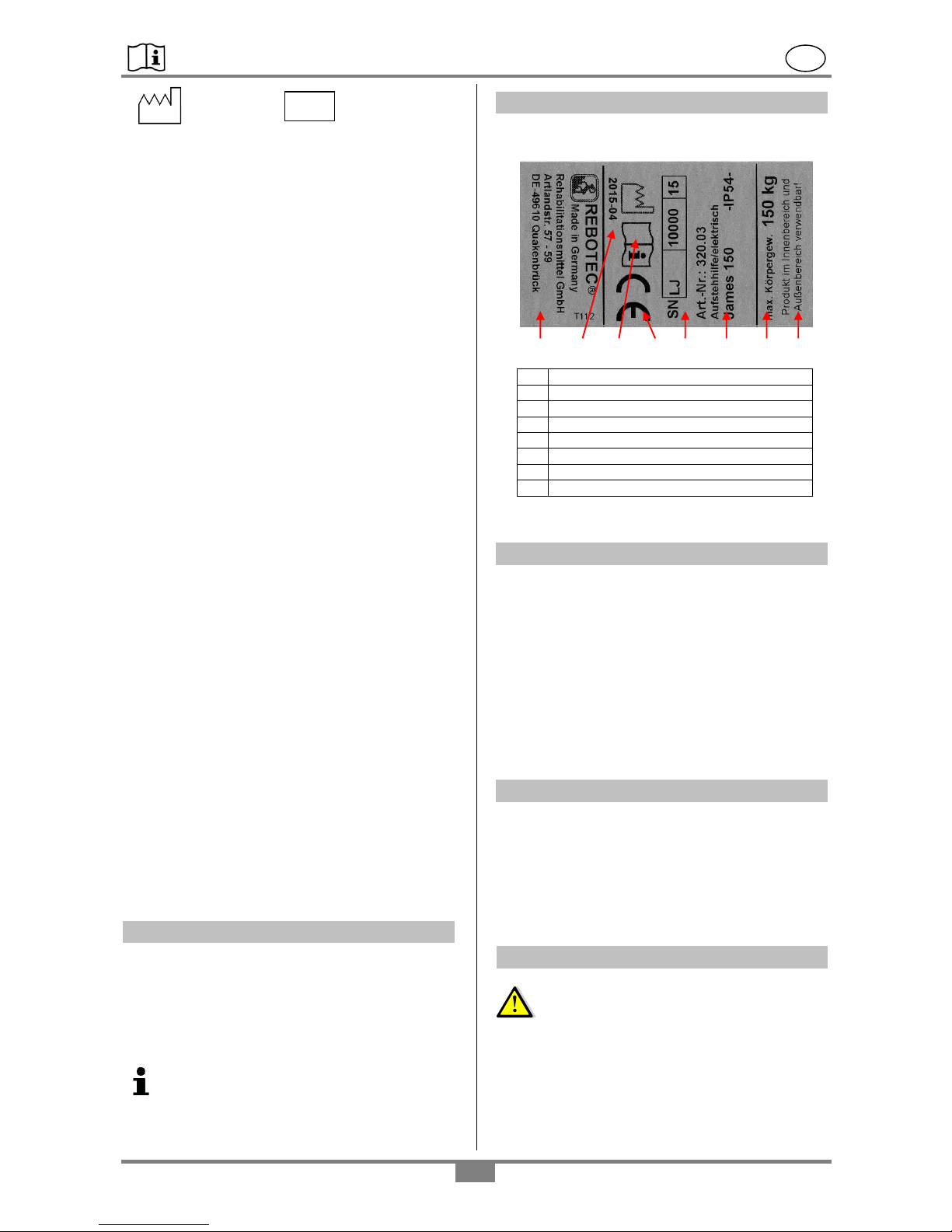
3. Nameplate / ordering of spare parts
In the nameplate you can find the following im-
portant information:
A
Mark of conformity (CE)
B
Serial number-product
C
Production year
D
maximum body weight
E
Product name
F
Note (use)
G
Read User Manual
H
Manufacturer details
The nameplate is very important for product identifi-
cation, and thus must not be removed.
4. Reuse, lifetime
The product is suitable for reuse. The number of
reoperations depends on the frequency of use and
manner of use of the product. Before reuse, the
product needs to be hygienically prepared and if
necessary the technical-functional safety of the
product need to be renewed.
If the product is used as intended, according to the
safety, the lifetime of the product is 5 years. The
effective lifetime depends on the frequency and
intensity of use, and the general condition.
5. Disposal
Products that can no longer be used are to be
disposed of separately from regular household
rubbish. This must be done according to the local
and national regulations for environmental protection and raw material recycling.
Please contact your local disposal company or
officials for further information.
6. Safety advisories for use
When using the Standing-up Hoist, the
following safety advisories must be observed:
Danger of slipping!
Before the first use, the User Instructions must
be read completely in order to avoid faulty operation or hazards.
Before each use, check the Patient Hoist for
visible damage or deficiencies.
B G A D E H F
C
SN
Page 4
REBOTEC / BA No.: 02.09.104/2016-12 GB
- 4 -
Operating and adjusting the Patient Hoist must
be done only by persons who are knowledgeable
and trained on how to properly handle the Patient Lifter. This requires the ability to use the
unit with patients.
Standing-up Hoist used in wet rooms may be
exposed to humidity moisture, chlorine and heat,
which can lead to oxidation that appears as a
white coating.
When functional faults or damage of any type
occurs, then the Patient Hoist may not be used.
Danger of breakage!
The maximum allowable load of 150 kg may
not be exceeded because no safe operation
can be assured.
Whenever using a sling, be sure that it is secure-
ly hung to the forked arm of the Standing-up
Hoist. Do not use any sling that shows signs of
damage.
Do not place any objects between the main col-
umn and the drive axis. No perpendicular loads
may be applied to the drive axis.
The patient must not hold onto the drive axis.
No weight loads may be hung onto the forked
arm for an extended time period.
Danger of injury!
The Standing-up Hoist may not be operated
while it is being charged up.
The Patient Hoist may be used only inside on
even, slip-free surfaces. Using the Patient Hoist
on slopes, grades or inclinations must be avoided due to the increased risk.
Use caution when travelling in tight spaces.
Paths used by the Standing-up Hoist must be
cleared before they are travelled on.
Sudden movements and pushing, as well as
patient-swinging must be avoided because of an
increased risk of an accident.
Never leave the patient unsupervised when us-
ing the Standing-up Hoist! An unforeseen
movement or action by the patient may lead to a
possible risk of injury.
In the event of an emergency lowering of the
patient, use extreme caution to avoid putting the
patient in danger. In difficult situations, seek the
assistance of another person.
Check for a secure connection between the
forked arm and the Hoist arm.
Danger! Function hazard!
It must be assured that no humidity reaches
inside the electrical systems. (Observe protec-
tion class!)
Do not open up the control / drive / battery unit or
hand switch systems!
If the drive doesn’t work (drive mustn’t start up
while it’s blocked) it’s not allowed to activate the
patient hoist.
Do not charge up the rechargeable battery in wet
rooms (e.g.: bathrooms, shower stalls).
Notice electromagnetic troubles caused by mo-
bile phones or medical equipment for example.
7. Product specifications
7.1 Delivery scope
The product has been carefully inspected in the
factory for freedom of defects and for completeness. After having received it, carefully check over
the product for possible transport damages and for
completeness.
1 Standing-up Hoist “James 150”
1 control unit
1 rechargeable battery
1 recharging cable
1 manual switch with hanging grip
1 User Manual
7.2. Technical specifications
We reserve the right to make technical developments and improvements with respect to the design shown in the User Manual.
Ratings
Standing-up Hoist James 150
Maximum load
150 kg (body weight)
Product weight
53 kg (without accessories)
Space req. max.
L x W x H
Standing: 110x65x200 cm
(Lifter arm all the way up)
Wheels Ø
Front: d = 75 mm, Rear: d = 100
mm with lock
Turning Ø
ca.115 cm
Knee pro. Height
50 cm to 75 cm (knee midpoint)
Lift height
84 cm to 150 cm
Lift cycles
Approx. 45 double lifts (depending on weight and charge)
Lifting unit
Stepless and without jerking
Protection class
II
Switch duration
2 min operation / 18 min. pause
Voltage (control
unit)
220-240V AC/50-60 Hz
Control unit
IP54
24V DC / 5A
Drive, complete
IP54
24V DC / 5A
Hand switch
IPX4
24V DC
Battery
IP54
24V DC / 5Ah
Operate/storage
5C to 45C / -10C to 50C
Operate/storage
Air humidity max. 85%
Safety
Mechanical emergency lowering,
Battery low charge, Power surge
switch off
Process tolerance: +/- 2 cm
8. Accessory, Spare parts
Article No.
Name, description
320.60
Soft handle for forked arm / 2 pcs.
02.09.104
User Manual - James 150
02.10.063
User Instructions for using slings
02.10.141
User Manual, slings
02.11.152
Maintenance Instructions
Page 5

REBOTEC / BA No.: 02.09.104/2016-12 GB
- 5 -
9. Setting up the for use
The product is delivered partially pre-assembled.
The following assembly instructions must be carried out before first-time use.
Step 1: Unpack
Remove the Standing-up Hoist out of the packaging and place it on a level floor.
Lock the wheel castors (see: page 8, section 13.)
so that the Standing-up Hoist cannot roll away.
Step 2: Install the control- and battery unit
Securely screw the control unit (K) to the column
(A) using both M6x16 screws (1) (included in the
accessories) using an SW5 Allen key.
Be sure that the red button of the control unit is
correctly positioned, facing the handle!
Step 3: Set up the column
Before setting up column (A), first unlock the wheel
brakes (F). To avoid damaging the paint coating on
the column, first straighten the pedal (D).
Notice the sign (X) at the bottom of the column.
Next lock the wheel brakes!
Step 4: Install the column
Remove the key ring (1) “or spring clip (2)” from
the bolt (3) and then pull the bolt completely from
the hole.
The column (A) can now be set up together with
the forked arm (B).
By inserting bolt (3) into the borehole, the column
(A) is arrested.
Next secure the bolt against slipping out by installing the key ring (2) “spring clip (1)” and then
tighten the M10 cap nut (4) to the column (A).
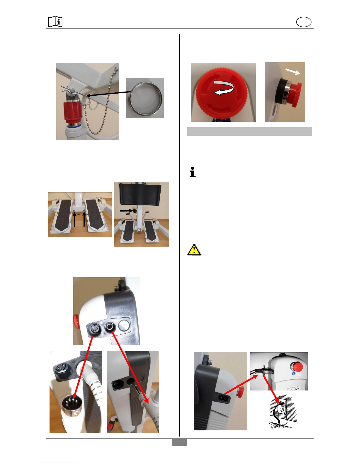
Step 5: Install the Hoist axis
To mount the drive motor to the Hoist axis, first
remove the key ring and bolt (1) “or spring clip (2)”
from the hole of the Hoist arm (A).
Next lift up the Forked arm (A) and align the borehole of the Hoist axis (X) with the Forked arm.
1 1 K
B
A
4
2
3 A 1
F
F D A
X
1
3
2
Page 6
REBOTEC / BA No.: 02.09.104/2016-12 GB
- 6 -
Then insert the bolt and secure it with the key ring.
Now the Forked arm is secured.
Be sure that the key ring or spring clip is fully
closed!
Step 6: Install the holder with knee protection
Unscrew the two screws (1) from the holder plate
(A), and fix the holder (B) with the knee protection.
By solving the star grip screw (2) the knee protection can be adjusted in height.
Step 7: Cable connections
Carefully insert plug (1) of the drive unit into the
jack (X) and the plug (2) of the hand switch into
jack (Y) on the side of the control unit.
Step 8: Emergency OFF button
Before starting up the Patient Hoist, the emergen-
cy OFF button must be deactivated. To do this,
rotate the button clockwise until it pops out.
10. Charging the battery
10.1 Rechargeable battery
If the lifting and lowering of the Hoist arm becomes
noticeably slower, then the battery charge is too
low.
Recharge the battery as soon as possible!
This extends the lifetime of the rechargeable
batteries. Rechargeable batteries that are
not used for an extended period of time
should be recharged every 3 months in order to avoid low charges. Otherwise the
charging capacity of the battery is negatively
impacted.
The lifetime of the batteries depends on the
loading and the charge level.
10.2 Connecting and charging
Observe the following instructions!
Check over the charging unit to be sure that the
connector cables or the plugs are not damaged.
DO NOT USE cables or plugs that are damaged!
Check the power mains supply (see 7.2) and
power supply fuse protection for the charging
unit.
The charging unit and the rechargeable battery
may not be opened under any circumstances!
The Standing-up Hoist may not be operated
while it is being charged!
Insert the flat plug (1) of the charging cable (see
accessories) into the jack (C) of the control unit
and then insert the plug (2) into the wall outlet.
2 1 C
Y
X
1
2
K
1 2 B
A
2
1
A
X
Page 7
REBOTEC / BA No.: 02.09.104/2016-12 GB
- 7 -
Depending on the battery charge level, the charging process can be as long as 14 hours. If the
charging process lasts longer than 16 hours, then
the rechargeable battery or the charging unit is
defective.
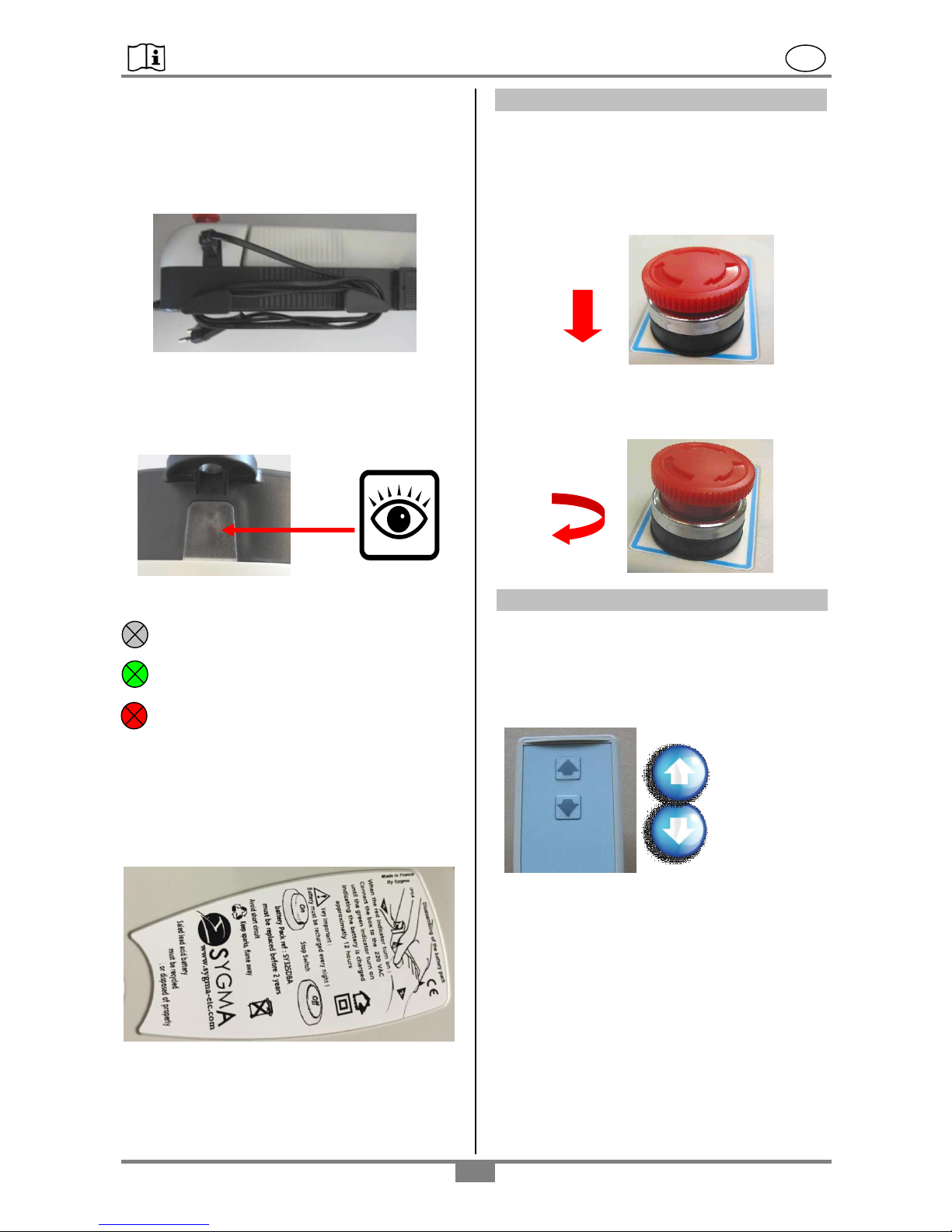
After charging, pull out the plug from the outlet and
then wind the cable around the holder for storage.
10.3 Charge level / indicator lamps
The LED charge level indicator lamp is located
below the window of the control unit. The LED
display is visible when looking directly at the window from above.
Indicator / LED
LED-dark: Battery capacity is sufficient
LED-green: Battery is fully charged!
LED-red: If the red LED illuminates when
activating the hand switch, then
it means the battery capacity is
too low.
Battery must be recharged!
10.4 Removing the rechargeable battery
The battery can be removed for replacing or for
storing. Look at the diagram on the battery unit.
11. Emergency OFF function
By pressing the red emergency OFF button, it
locks into position. The drive system is interrupted
and cannot be operated with the manual switch. It
is activated in emergency situations and in the
event proper operation of the Standing-up Hoist is
impaired.
By rotating the emergency OFF button clockwise,
it will pop back out and is thus released. The drive
unit can then be operated using the manual switch.
12. Manual switch
The drive unit is activated with the manual switch
(steeples adjustment) and activates “lifting“ and
“lowering“ of the Forked arm.
For the desired action, the button is kept pressed
down. When releasing the button, the drive automatically stops.
Stop
Start
Lift
“UP“
Lower
“DOWN“
Page 8
REBOTEC / BA No.: 02.09.104/2016-12 GB
- 8 -
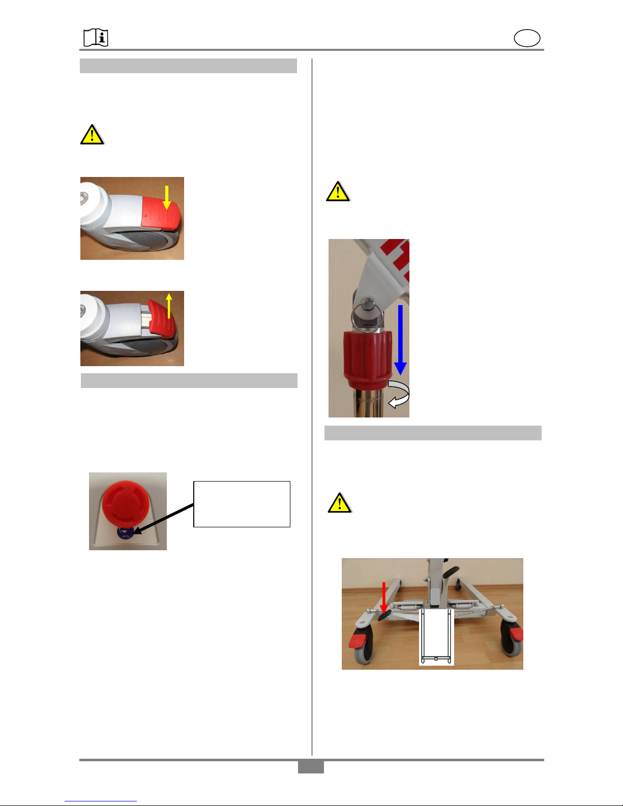
13. Wheel brakes
Both wheel brakes are an important safety feature
whenever using the Patient Hoist. The back swivel
castors are equipped with wheel locks and allow
locking of the rear wheels.
Danger – Risk of tipping over!
Both rear wheels must be locked.
Press the wheel lock
levers down with your
foot. The wheels are
now locked and the direction is secured.
Be sure that the wheels
are not swivelled inwards.
The wheel brakes can
be released simply by
lifting up the lever with
your foot.
14. Emergency lowering / jamming protection
14.1 Electrical emergency lowering
If the hand switch is out of order due to a defect,
yet the electrical system is still able to function
(battery is sufficiently charged), then the lifting axis
can be lowered one more time by using the emergency OFF button.
14.2 Mechanical emergency lowering
In the event the patient becomes exposed to an
emergency situation, or an electrical defect occurs
with the drive motor, or the control unit fails or the
battery is completely uncharged, then it is necessary to use the mechanical emergency lowering
system.
Before using the emergency lowering, it is absolutely necessary to interrupt the power supply from
the battery. Press the emergency OFF button!
Danger-Risk of injury!
When using emergency mechanical lowering,
do not stand under the forked arm!
Start lowering
Grab the red rotary grip and
pull it downwards until it
clicks into position. For lowering the drive axis, grab the
red rotary grip and turn it
counter-clockwise.
Stop lowering
Let go of the red rotary grip
and turn clockwise a half
turn until it clicks into position. Lowering is now
blocked.
15. Stability – spreading the base
The foot pedal allows the spreading of the base
members (left and right) and thus facilitates moving the unit to the area of use. Press the foot pedal
all the way down to the stop.
Danger of tipping over!
Spread the base members only when the rear
wheel locks are fully disengaged!
Not spread apart
Hold the button
pressed down
to lower!
Page 9
REBOTEC / BA No.: 02.09.104/2016-12 GB
- 9 -
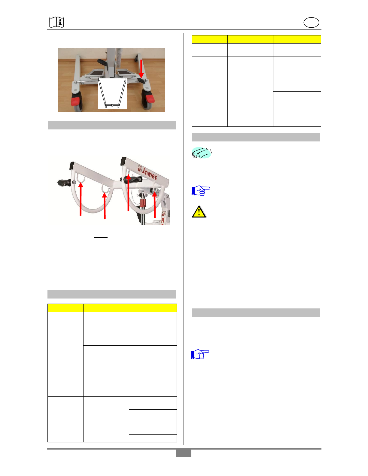
Spread apart
16. Forked arm (carrier for slings)
The forked arm (B) serves for attaching the sling.
The sling holds the patient, who then can stand up
and be moved over.
Hanging the sling must be done using both hooks
(1 or 2) so that the load is evenly distributed.
Depending on the application, there are several
different types of slings systems offered by REBOTEC. To assist you in selecting the most suitable
sling system, a guide is available (see: page 5,
section 8.).
17. Troubleshooting
Fault
Poss. cause
Correction
Drive does not
function
Emergency OFF
button is activated
Disengage emergency OFF.
Bad electrical
connection
Check the connection.
Defective power
cable
Inspect the cable.
Battery is too low
Charge up battery.
Lift unit is jammed
Check for freedom
of movement.
Battery has no
contact
Re-install battery,
Check position.
No battery
Insert battery.
Battery does
not charge
Display does not
illuminate green
after the end of
charging
Check power mains,
Check power cable
and contact and for
damage
Battery is defective,
Display/LED faulty
Fault
Poss. cause
Correction
Battery not fully or
not quite installed
Fully install battery,
Forked arm
does not drive
all the way up
or down
Battery capacity is
too low.
Charge up battery.
Forked arm is
jammed
Loosen the screws
at the column.
Manual switch
does not
function
Button(s) have no
function
Button(s) defective.
Check cable / plug
contact.
Greatly reduced speed,
loud noise
Motor, drive defective
Do not operate the
drive system. Do
maintenance!
18. Care
In general the Standing-up Hoist can be
cleaned using a mild conventional cleaning
and disinfecting agent. Simply wipe the
product with clean water and cloth, and
then wipe dry with a clean cloth.
Maximum cleaning temperature of
65C must be observed!
The Standing-up Hoist must not be
washed inside an automatic washing
unit!
Do not use an abrasive scouring agent or cleaner
(read the product instructions!) that contain aggressive solvents (acids, thinners, benzene). Do
not use stiff cleaning brushes, as these will damage the painting or cause deposits to build up on
the steel parts and other materials.
Emergency lowering
The emergency lowering mechanism may not be
treated with oil, grease or other lubricant. This will
lead to faulty function when lowering.
19. Maintenance
Accidents or damage may be caused by the late
detection of wear and/or improper use, as well as
irregular or no maintenance.
For safety reasons and for preventing accidents, the Lifter must undergo a com-
plete maintenance at least once a year.
(Refer to the Medical Products Act and the
local regulations.)
Maintenance scope
Check at regular intervals:
The time intervals depend on the frequency of use
and the condition of the product.
The product for visible damage (cracks, break-
age, loose parts).
1 B 1 2 2
Page 10
REBOTEC / BA No.: 02.09.104/2016-12 GB
- 10 -
All screw connections for tightness (especially
the wheels and carrier).
Emergency lowering at least semi-annually (mal-
functions – carry out maintenance!)
Rolling smoothness, castor function (replace any
defective castors).
Drive unit function, test manual switch (replace
defective articles).
Cable connections and plugs for damage.
Sealing edges of the control and battery unit.
Test the emergency OFF function.
Inspect the accessories for deficiencies.
Repair
If you have questions concerning maintenance
and repairs to the chair, then contact an authorized dealer or medical equipment supply outlet.
When making repairs, use only original spare
parts from REBOTEC. Observe all advisories
concerning guarantee and warranty.
Never make any unauthorised modifications or
conversions to the chair. These will only adversely affect the safety and function of the
chair. In such cases REBOTEC assumes no
liability!
Follow all the instructions when ordering spare
parts, re-use and product lifetime of the chair.
After a complete maintenance or repair of the
chair is done, we recommend a complete cleaning for assuring hygiene. Follow the cleaning
instructions.
For documenting maintenance, REBOTEC
supplies a Maintenance Report – Chairs.
Here you will find information on mainte-
nance and forms for documentation.
You can order the User Manual and Maintenance
Report or see via our website at www.rebotec.de.
It is possible to print out the information and to
read it as needed
Page 11
REBOTEC / BA No.: 02.09.104/2016-12 GB
- 11 -
No.
Art. No.
Name
Piece
1
420.70.71
Linear motor drive, type B / 5A)
1 2 420.11.72
control unit, type B / (220-240V AC/50-60 Hz / 24VDC / 5A)
1 3 420.11.73
battery unit, type B / (24VDC / 5Ah)
1 4 420.70.75
handset, type B / (24VDC)
1 6 443.10.80
castor (Ø 75 mm)
2 7 443.10.85
castor with brake (Ø 100 mm)
2 8 420.00.15
pedal rubber covering
2
9
420.00.12
foot pedal
1
10
420.28.83
od angle joint (L=280 mm)
2
11
420.99.22
handle Ø 22 mm
2
12
420.00.51
fork arm
1
13
420.00.60
knee protection unit complete
1
14
420.00.66
knee cushion
1
15
320.60
handle for fork arm
2
16
420.70.79
recharging cable
1
11
10
12
1
4 6 9 8 7
16
2
13
14
15
3
20. Spare parts: James 150/320.03
Page 12
REBOTEC / BA No.: 02.09.104/2016-12 GB
- 12 -
Notes:
Other products we deliver…
Walking Aids
Walking Sticks
Crutches
Products for bath and toilet
Shower Stools
Shower / Commode Chairs
Shower / Comm. Wheel Chairs
Shower Transport Wheel Chair
Multifunction-Wheel Chairs
Rollators
Patient Hoist
Standing Up Aids
Give us a call…
…we’ll gladly inform you!
Your REBOTEC-Team
 Loading...