

Page 1

Instal l a t i on Manual
Model : BX 400 0
V 2.3.7
• Thank you for using the Smarty BX4000 Drive Recorder .
• Before using t he Smarty, please ensure that you read and
understand t his user guide.
• Please store this user guide in an easily accessible location.
• Before connecting and installing this Drive Recorder, please
refer to this instruction manual for proper operation.
Page 2

FCC
INFORMATION TO THE USER
This equipment has been tested and found to comply with the limits for a Class
B digital device, pursu ant to par t 15 of the FCC Rules. These limits are
designed to provide reasonabl e protection against h ar mful i nterference in a
resid ent ial i n st allat ion . Th is equ ip m en t gen erat es, u ses and can radi ate rad io
fr e que nc y energy and, i f not installe d and used in acco r da nc e with the
instruc tions , may cause harmful interference to rad i o commu nicat ions.
However, there is no guarantee that interference will not occur in a particular
installati on. If th is equipment does caus e harmful interference to rad io or
television reception, which can be determined by turning the equipment off and
on, the user is encouraged t o try to correct t he interference by one more of the
following measures :
-Reorien t or relocat e the receiving ant enn a.
- Increase the separation between the equipment and receiver.
- Connec t the equipment i nto an o ut let on a cir c uit dif f erent from that to whi c h
the r eceiver is connected.
- Consult the dealer or an experienced radio/TV technician for help.
WARNING
Any change s or modifica tions not expressly approved by the
manufa cturer could void the user’s authority to operate the equi pment.
2
Page 3
SAFETY ADVICE
CAUTION
RISK OF ELECTRIC SHOCK
DO NOT OPEN
CAUTION: TO REDUCE THE RISK OF ELECTRIC S HOCK,
DO NOT REMOVE COVER.
NO USER-SERVI CEABLE PAR TS INSIDE.
REFER SERVICI NG TO QUALIFIED SERVICE PERSO NNEL.
Please m ak e su re you follow t h e safety ad vice/instructions given in the user guide.
Caution
RISK OF EXPLOSION IF BATTERY IS REPLACED BY AN INCORRECT TYPE.
DISPOSE OF USED BATTERIES ACCORDING TO THE INSTRUCTIONS.
Battery for RTC(Real Time Clock) inside
Caution
Install the product wher e it doe s not bloc k dr iv e r’s vis ibil ity
and where there is no airbag installed. This could cause an
accident or might injure the passengers in case of acci dent.
Caution
Damages due to production malfunc tion, loss of data, or other damages occurring w hile
using this product shall not be the responsibility of the manufacturer. Although the
product is a device used for recording videos, the product may not save all videos in the
case of a malfunction. In the case of an accident, the sensor may not recognize the
shock when the impact is light and as a result it may not begin recording automatically.
Caution
When the impact is light like very light, such as a minor bump in the road,
the G-sensor may not recognize the impact and as a res ult it may not begin
record ing automat icall y. Test and set your own G-sen s or level for your veh icl e.
WARNING:
TO PREVENT FIRE OR ELECTRIC S HOCK HAZARD, DO NOT EXPOSE
THIS APP LIANCE TO RAIN OR MOISTURE.
3
Page 4

GPS Reception
1. Activate the product in an area without larg e buildings
to improve GPS reception.
The com m erci al p urp os e GPS has the average rag e error of m ore
than 15 me te r s and the r a nge err o r could be mor e than 100 mete r s
du e to environmental c onditions l ike buildings, roadside trees etc.
2.
The temperature range for optimum operation of t he GP
S receiver i n your car is -10 ~ 50
3. Wh en using the product for the first time or after a long
period (more than three days), it may t ake a l i t t l e longer
to recognize your current location .
It may take between five and thirty minutes to get GPS reception.
GPS recepti on may be i mpai r ed under the following circums tances.
1) If there is an object at th e end of the GPS antenn a
2) If you r vehicle has m etallic elements on t he wind shields
3) If equipment generating electromagnetic waves that interfere with the GPS
signal is in stalled in the vehic le e.g.: Other GPS devic es such as a certain
type of wireless act ivated alarm s , MP3 and CD players an d camera al arm s
usi ng GPS.
4) If you are usin g a receiver connected by cable, electric interference can be
avoided b y sim p ly ch an gi ng the location of th e receiver ( ant en n a).
5) On heavily overcast or cloudy days, if the vehicl e is in a covered location
such as under a bridge or raised roadway, in a tunnel, an underground
roadway or parking area, inside a building or surrounded by high-rise
buildings.
6) If GPS signal recepti on is poor, it may take long er to loc ate your current
position when the vehicle is moving than when it is stationary.
°C.
4
Page 5

CONTENTS
You should have a s et of the following items with each BX 4000 ord er .
1. Smarty BX4000 unit
2. 4GB-32GB SD memory card
(PC Viewer software i s
on the provided SD card.)
3. GPS Antenna module
4. Remote / Panic Switch
5. Audio/Video output cable
6. Power Cable
7. Camera input cable
8. Wire Splice clip (5pcs)
9. Sticker (double sided tape 1pc)
10. Velcro S ticker (1pc)
5
Page 6

OPTIONAL ACCESSORIES
You may have one or m ore of th e following it em s with your B X4 0 0 0 order.
11. STR-100IR
-Inter i or Fac ing Camer a
-Plu gs in t o “ Cam 1 -3” sl ot
12. STR-100
-Forward F ac in g C amera
-Plu gs in t o “ Cam 1 -3” sl ot
13. DTR-100
-Wide Angle Forward Camera
-Plu gs in t o “ Cam 1 -3” sl ot
14. STR-131
-Rear bac k -up C amera
-Plu gs in t o “ Cam 4 ” slot
14. MIC-100
-Wired Micr ophone Exten s i on
(mic also built-in to BX4000 recorder)
15. SLB-100
-Locking Enclosure/Mount
6
Page 7
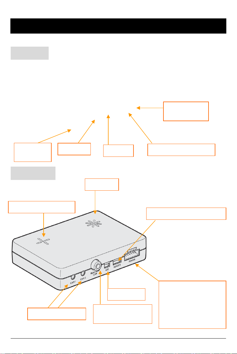
INTRODUCTION
FRONT
Audio/Video
Output
Camera 3
Input
SD Door
REAR
Internal Microphone
Camera 1, 2 In p ut
SD Slot
BUZZER
GPS Input
Rear View
Camera 4 Input
External MIC input
Remote Control Input
Power Input
&
Alarm (Car Signal)
Input
(Turn left, Turn right,
Br ake, Sp eed p u ls e)
7
Page 8
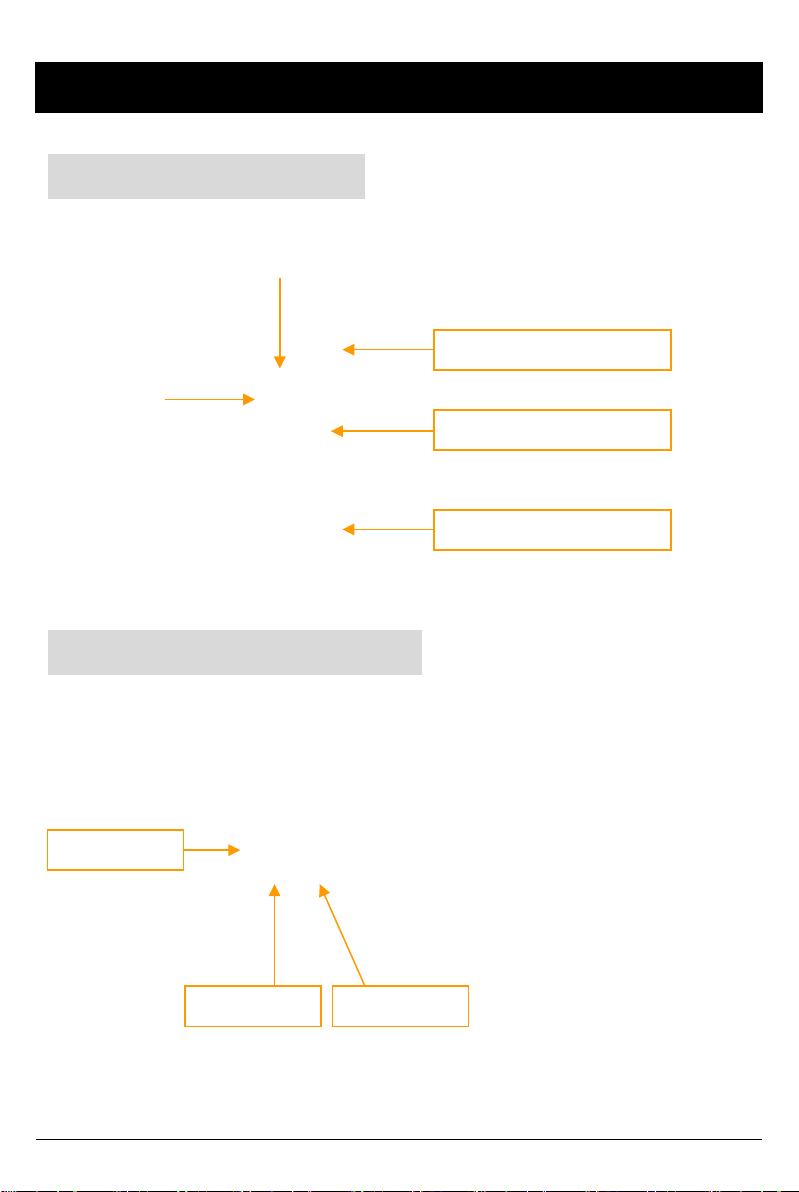
INTRODUCTION
REMOTE CONTROLLER
Record LED
BLUE LED
Error LED
RED LED
Audio Video Output Cable
SH UTTER BUTTO N
PLAY BUTTON
PANIC B UTTON
Audio out 1
Video out 1 Video out 2
[Not e] The same screen will be shown through the Video out 1 & 2.
8
Page 9
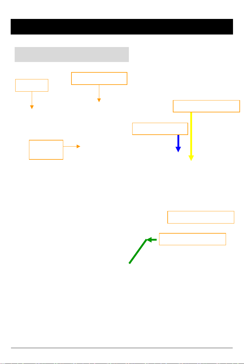
INTRODUCTION
Power & Car Signal Input
Black (Ground)
Red(+)
FUSE
250V 3A
Yellow (Alarm 3)
BLUE (Ala r m1)
White (Spe ed pulse)
Green (Al arm 2 )
9
Page 10
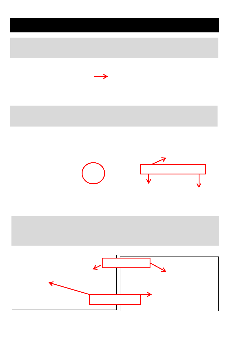
HARDWARE INSTALLATION
1) Ins ert BX 4 00 0 Recor der in to loc ki ng c ase
*If no locking c as e, us e pr ovided Velcr o adhes i ve
2) Fi nd instal lat i on loc at ion for Recor der & l ockin g cas e (i.e glove
box, u nder dash , t ru nk , etc. ).
Screw holes for mounting
3) In stall th e i nterior and exter i or camer as with 3 M dual s ided
adhes ive t o the windsh i eld as seen below. Ch 1-3 provide 5V
power to the foll owin g cameras: STR -100/IR, DTR-100, STC-300
Interior Cam era
Exterior Cam era
10
Page 11
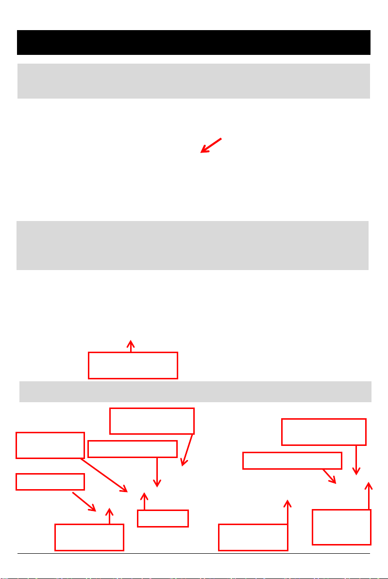
HARDWARE INSTALLATION cont’d
4) Ins tall R emote C on trol ont o dash next to the s teer ing wheel
and with in reac h of the driv er.
5) Run remote & camera cable(s) and secure in headliner or
other area so n o cables are exposed. U se provi ded wire clips i f
nec ess ary. C ables s h ould en ter th rou gh r ear of the loc kin g cas e.
Make sure cables go
through this opening
6) Con nec t all c ables to B X 40 0 0 R ecor der
Power Input &
Alarm trigger cables
Cha nnel 4
input ( optio nal)
Camera 1 Inp u t
Camera 2 Inp u t
(optional)
Remote Control I nput
GPS Input
Camera 3 Inp u t
(optional)
External Mic input
(optional)
SD card input (32GB)
LCD mon itor
Connection
(optional)
11
Page 12
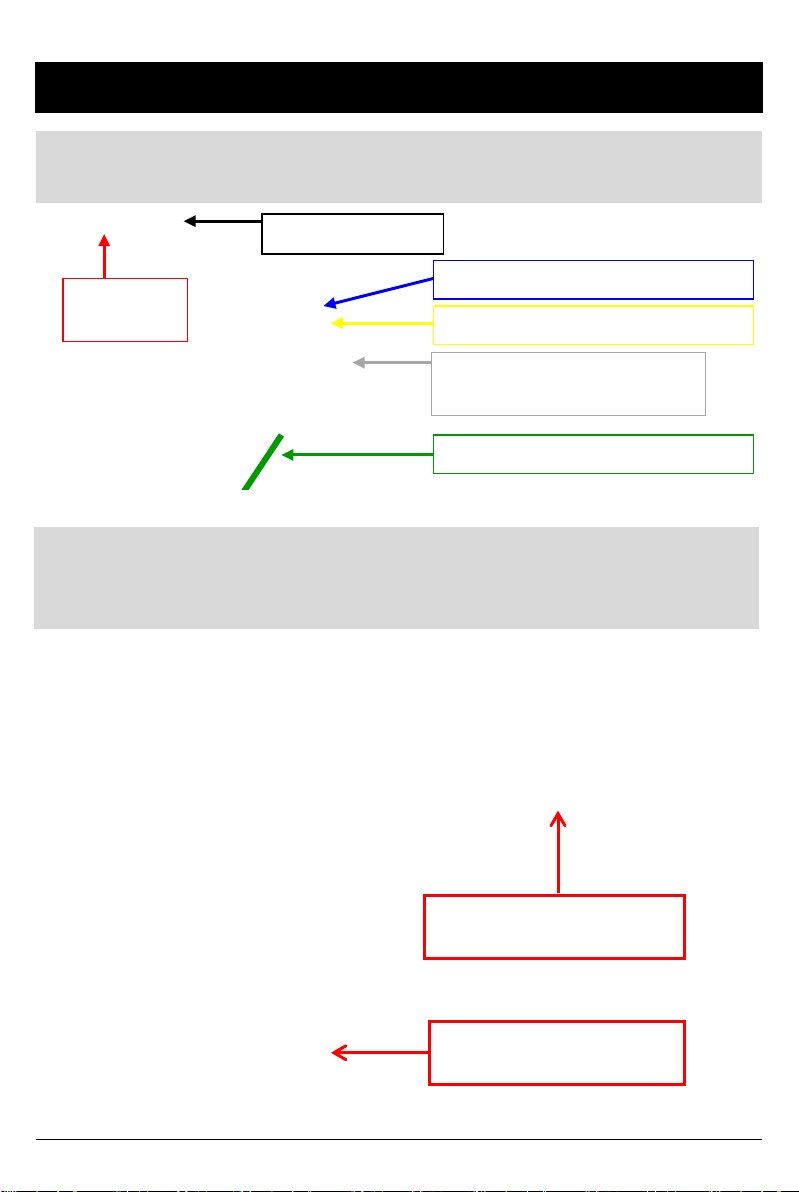
HARDWARE INSTALLATION cont’d
7) After all cables are in ser ted in to rec order, c onn ect th e 12V
Alar m tr iggers ( Bl ue to the dome li ght , Gr een t o the t axi meter)
Black (Ground -)
Red
(Power +)
BLUE (Ala r m1 - Optional)
Yellow (Alarm 3 - Meter)
White (Spe ed pulse)
NO USE
Green (Al arm 2 - Door)
8) Mak e sur e veh ic le ign iti on is off and key s are ou t, t hen con nec t
RED power (+) cable to vehicle f u se that is powered with igni t ion
(i.e radi o) . Con nect Black Grou nd ( -) to car chassis.
Red Power Cable (+)
Connected to vehic le fuse
Black Grou nd Cable (-)
Connected to car chas sis
12
Page 13
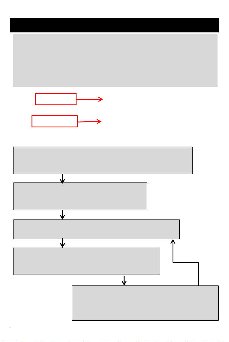
HARDWARE INSTALLATION – CALIBRATION
9) A fter power c ables and tri gger cables are properly conn ected and th e
BX4000 system is installed, The internal G-Sensor must be calibrated. It
detects t he inst alled direction of the BX4000 (vertically or hor i zontally) for it t o
accu ratel y rec ord th e journ ey d irec tion .
Pres s and hol d [PANI C] & [SH U TTER ] button togethe r and then po wer on
(turn on i gni ti o n) .
Panic Button
Shutter Button
Thi s G -Sensor calibration is only needed at the first time the BX4000 is used.
Press and hold panic and shutter button
simultaneously more than 2 sec for calibration
Press any single button to escape
Park vehicle on a flat surface with
at least 50 meters of space directly ahead
and press panic button once
Move directly forward and accelerate vehicle till beep
sound occur
G-Sensor Calibration is finished successfully
Press any button or wait 30 seconds to reboot
If G-Sensor Calibration has failed,
Park vehicle on a flat surface with
At least 5 meters of space directly ahead
And press panic button once again
Retry
13
Page 14

Remote Controller LED status Indicators
Before
Overwriting
During
Overwriting
Status
Ini tial Power on ON ON
Booting ON/OFF ON/OFF
Pre E vent r ecording
Conti nuo us r e c o r di ng
Event recording
Eve nt rec o r di ng during co nti nuo us
rec o r di ng mode. ( 5seconds)
SHUTTER recording
Pre E vent r ecording
Conti nuo us r e c o r di ng
Event recording
Eve nt rec o r di ng during co nti nuo us
rec o r di ng mode. ( 5seconds)
SHUTTER recording
Panic Folder is fu ll OFF ON
During Playback
OSD menu
Camera F ailur e / Vid eo Loss
SD Card fail
Blue
LED
ON OFF
ON/OFF
Quickly
ON/OFF
Quickly
ON/OFF
Quickly
ON OFF
ON/OFF
Quickly
ON/OFF
Quickly
ON/OFF
Quickly
ON/OFF OFF
ON/OFF
Slowly
ON/OFF
Slowly
Red
LED
OFF
OFF
OFF
OFF
OFF
OFF
ON/OFF
Slowly
ON/OFF
Slowly
14
Page 15

FUNCTION (MAIN UNIT)
Automatic start
Make su re t hat periph eral s, in cl ud in g cameras, are p rop erly con n ect ed .
Turn on the vehi cle power, BX4 00 0 will autom atic ally st art. (Use the power
cable p rovid ed . )
Notice : The unit will n ot st art record ing im med iately after the power is
turned on. It take s up to 1 minute for the built-i n power bac kup s y s te m
to charge. Th er eafter, the int er nal flash m emory will be ready t o r ecord.
Event recording
The Event rec or ding will be start ed automatically b y Motion detection , Alarm1,
Alarm 2, Alarm 3, and/or by the G-sensor level.
The emergency recording can be activated by pressing the [PANIC] button.
Normal recording (Cont inu ous record)
The Norm al (con t in u ou s) record in g will b e autom at ic ally st art ed aft er p ower u p .
BX4000 will not make a separate eve nt fil e during the continuous r e cording.
It will m ark or “ flag ” t h e Event area as ‘A larm 1 ~3 ’, G-sen or, M oti on d et ect ion or
[PANIC] butto n i n t he cont inuous re co r di ng fil e , whi ch can be ea s il y searc he d for
du rin g playback. The al arm s c an also b e dis p layed on th e video im ag e.
Dual record M o de (Event & Norm al recor d )
If you set di fferent record mod es per camera, i.e camera1 set as Event record
and camera 2 set as Normal record, then camera1(Event record) will work
according to the record setting for example 10 fram es p er second recor ding.
However camera2 (N or mal record) will record 1frame per sec ond, if there is no
event. If there i s an Event, both cameras will record acc or ding to the record
sett ing for exampl e 10 frames per second recording .
Live image on LCD Monitor
BX4000 will display the live video image on the LCD monitor.
The camer a channel c a n be changed using the i nf o r ma t ion on the OSD.
(Refer t o page 13)
Playback in the car
Record ed files can b e played back i n th e car usi ng LCD moni tor and remot e.
PC View er Softw are
The s oftware is pre-loaded on the SD card i n the “pcsw” folder.
15
Page 16

FUNCTION (MAIN UNIT)
SD Memo ry Card Format
Remove the powe r first. Press and hold the [PLAYBACK] & [PANIC] button.
Then connect the power.
Press and hold the [PLAYBACK] & [PANIC] more than 2seconds after
booting. Then SD card in itialization will start.
Once complete, all video & log files will be deleted and the configu r ations
will default to the factory settings.
*This function can also be performed on a PC with the PC viewer
software.
Notice : PC Viewer software i s pre-load ed on the SD card. Please ensu r e
you have in stalled the software to your PC before you format t he card.
Built-in power backup (Super Capacit or)
When power to the unit is inte r r upted, BX4000 s a ves the la s t fi l e using the
internal Super Capacitor.
BLUE LED (RECO RD)
The blue LED shows the power is on.
The blue LED blinks slowly during proper operation / recording.
RED LED (ERRO R)
The red LED will be turned on when:
1) There is an SD card er r or
2) The BX4000 is powered on and during the boot-up time (20 sec – 1 min
after power on )
3) The “Panic” recording folder is full and needs to be purged
4) There is video signal loss or camera error
VIDEO LOSS
The RED LED will go on to p rovide visual indication of video loss .
Check the camera and camera connection and turn off and on the unit to attem pt
to resol ve the is sue.
Also, mak e sur e the num ber of cameras that you conn ect is the same amount that
You have selected in the settings (check settings menu on Installation software).
16
Page 17

OPERATION
1. Make sure that the power cable is properly connected and turn on the car
power/ignition.
2. Blue LED & Red LED will turn on and slowly blink simultaneously. After
boot i s complete, the Blue LED will remai n on. Blue LED l i ght means
BX4000 is now ready for the event recordi ng or has started th e Normal
recording (Continuous recording).
3. The norm al rec ord in g (Con t in u ous record in g) will be aut om at ical ly s t arted ,
if this is t he record mode you have set with th e PC viewer software.
4. The Event r ecording will be started au tomat ically by Motion det ection ,
Alarm1, Alarm 2, Alarm 3, and/or by the G-sensor level and will begin w i th
one short “Beep” soun d.
5. The Emergency recording can be started by pressing the [PANIC] button.
Removing the SD memory card
Tur n off the power and then chec k the BLUE LED l i ght. Once the BLUE LED
light is off, take out the SD memory card.
Insertin g the SD memory card
Tur n off the power and then chec k the BLUE LED l i ght. Once the BLUE LED
light is off, insert t he SD memor y card. Always insert memory card when
power is OFF.
SD Card Erro r
Occ asionally SD cards may fail and may need to b e “ i nitialized”. Ini tializi ng an
SD car d bas i cally clears out th e bits of data that may be collec ted over time,
which m ay cau se record in g errors . Thi s is norm al an d the natu re of flash
memory. I f there is an SD card failure, th e RE D LED ligh t will blink on th e
remot e con t rol* . To resolve t h e prob lem , in it ializ e th e SD card with th e
installati on s oftware (see installat ion software manual). If the initialization is
un succ essful or there is still a r ecord error, you m ay need to replace the SD
card.
*The RED LED wil l also blink in case of c amera/vi deo l oss . So m ak e sure the
cam er as are functi oning proper l y fi r st. .
17
Page 18

OPERATION
PANIC RECORD BY PANIC BUTTON
The panic recording by [PANIC] button will start by pressing the [PANIC] button
wi th one sho r t “Be e p” sound. Bl ue LED will be blinking duri ng t he pa ni c
recording.
BX4000 do e s n’ t make a sepa r a te panic f i l e during the co nt i nuo us r ecor ding.
It w il l mark the panic ar e a by [PANIC] butto n i n the c o nti nuo us r e c o r di ng file
which can be easily searched for during playback.
SNA PSHOT RECORD BY SHUTTER BUTTO N
Press [SHUTTER] button.
Then BX4000 will take a snapshot of 1 image with 5seconds audio with one
short “Beep” sound.
18
Page 19

SOFTWARE USER GUIDE
BX4000 PC Viewer Guide
[PC SYSTEM REQUIREMENT]
Recommen ded PC specificati ons for PC V iewer s oftware
OS Windows 2000, Windows XP
Windows Vista, Windows 7
CPU Penti um4 2.6GHz or higher
RAM 512MB or highe r
Interface SD Memory Card Read er
HDD
Free sp ace
Display 1,024 x 768 pixel/High Color(16bit) or higher
If the PC does not meet the minimum system requirement, the PC
Viewer may not function properly.
Instal l 20MB o r higher
Back up 2GB o r higher
19
Page 20

PC SOFTWARE INSTALLATION
PC Viewer software is on the provided SD card.
1. Con nect the S D card into your PC (i f your computer does not have SD c ar d
slot use a USB SD card reader) and go to your removable storage devices via
“My Comput er”
2. Right-click the “DRIVEREC4” drive and select [Open]
3. Double click [SETUP.EXE] in the [pcsw] folder.
4. Select the language and then follow the dialog box.
5. The “PCV iewer” ic on will be displ ayed on your d esktop.
NOTE: To Un-install the “PC Viewer BX4000”
Open the “Control Panel”
Select [remove program] and remove [PC Viewer BX4000]
20
Page 21

Connecting SD card
1. Inser t SD car d into your PC.
2. Run “PC Viewer BX4000”
3. Select [F ile] and then click “S elect Dat a Fold er” or Clic k [ OP E N] butt on
or
[OPEN] button
4. Sel ect SD memor y card folder at the folder select wi ndo w and cli c k “OK”.
21
Page 22

Apply your Drive Recorder Settings
14 . Clic k [Drive Record er Set tin gs] icon for set up.
[Drive Recorder Settings] icon
Caution
Before clicking Init SD card button or before changing the Record Mode
make sure to bac kup the SD card data first. Al l normal record ing dat a or all
event recording dat a in SD card will b e automatical ly deleted to make free
spac e on the SD card. O nce the SD card is in i tialized or t he new set tings
are saved, th e old data cannot be recovered.
Init SD card : All data will be de leted and the co nfigura t ion settings will
default to the factory settings (unless you select “backup config file”).
Record Mode Change: All norm al record i ng d at a or all event r ecord in g
data i n SD card wil l be automat ically deleted to make free space on the SD.
22
Page 23

Drive Recorder Settings – Record Mode
To record Camer a2 or C am era3 , C am era4 ch eck “Use” b ox.
To record Audio, chec k “Record Audio” box.
To use Motion Detection as an Event, check “Motion” b ox per camera.
Record Mod e Normal Mode: Continuous recording will automatically
start after booting the BX4000.
Event M ode: Record i ng b y Motion Detec t ion , G -sensor,
Alarm1~3 or [PANIC] button.
Dual Mode: Continuous recording will automatically
start after boot ing and mak e a sep ar ate event recor ding
file when t here i s an event.
Motion Sensitivity Select Mot ion Det ect ion S en sit ivit y from 1 to 5.
5 (Hi gh) : The most se nsi ti ve
4
3 (middle): Default value
2
1 (low): Least sensitive
To record by Motion Detection
Check Motion p er cam er a and set Record Mod e as Event Mode.
Dual Recording and Dual Mode
If you set dual record mode or differen t r ecord mod es per camera, like
camer a1 s et as Event rec ord and camera2 set as Normal rec ord , t h en
camer a1(E vent recor d) will work accord ing to th e Fps(E ) sett ing for
exampl e 10frames per second recording and camera2(Normal recor d) will
work accord ing to the Fps(N ) setting for example 1 frames per second
record in g or sam e as Fps( E) set ti ng .
23
Page 24

Drive Recorder Settings – Resolution & Frame Rate
Resolution PAL: 720x576, 720x288 NTSC: 720x 480, 720x 240
Frame Rat e 1 Camera support s 1~25 fps@ 720x576, 1~25 fps @ 720x 288
1 Camera support s 1~30 fps@ 720x480, 1~30 fp s @ 720x240
2 Cameras supports 1~12 fps @ 720x576, 1~25 fps @ 720x288
2 Cameras sup ports 1~15 fps @ 720x480, 1~30 fps @ 720x240
3 Cameras supports 1 ~ 8 fps @ 720x576, 1~12 fp s @ 720x288
3 Cameras sup ports 1~10 fps @ 720x480, 1~15 fps @ 720x240
4 Cameras supports 1 ~ 4 fps @ 720x576, 1~12 fp s @ 720x288
4 Cameras sup ports 1 ~ 5 fps @ 720x480, 1~15 fps @ 720x240
Quality(4 level) Super (Large file size, but good picture quality)
Low (Small file size, but low picture quality)
Pre Event
Post Event
Overwrite Overwrite (The image data is overwrites the oldest files when the SD
Event Ratio
vs. Panic Ratio
Pre-record/Post-rec ord tim e can be set here.
Pre-record t im e is 5~30sec, if total frame rat e is bel ow 8fps @ 720x576 or
10fps @ 720x480.
Pre-record t im e is 5~25sec, if total frame rat e is 12fps @ 720x576 or 15fps
@ 720x480.
Pre-record t im e is 5~15sec, if total frame rat e is 25fps @ 720x576 or 30fps
@ 720x480.
Post-record tim e is 5~300sec
memory is full.)
One ti me (The recordin g stops aut omatical ly when the SD memory is full.)
Set the Event data percentage and the Max Number of Panic event data
percentage.
If you set the event record mode only: 100% of SD card capacity is for the Event
recording data.
If you set the normal rec ord mode only:100% of SD card capacity is for the
Normal recording data.
If you set dual record mode or different record modes per camera (i.e. Cam 1
is Event record & Cam2 is Normal record): Then, for example, 50% of SD card
capacity is for the Event recording data and 50% of SD card capacity is for the
Normal recording data. This % is adjustable by using the scroll bar.
*The total # of Events (including Panic and Event) cannot exceed 1,600.
24
Page 25

Drive Recorder Settings – Alarm Triggers
To record t he car sig n al with vid eo, s et th e Alarm con fig u rati on as below,
To use the Alarm as an Even t t r igger , (i.e.: so Event r ecording will s tart when a
door is open or Met er is on) set the Alarm con fig u rat ion as below,
To use the Alarm as a changing live D isplay tri gger, set the Dis play configurat i on,
G-Sensor setting
If G -s ensor sensitivity value is too hig h like 5, it becomes too sensitive, so i t will
dete ct ev en a light impa ct o r light turn. If G-sensor sen sit ivity value is too du ll, so it
might no detect a notable incident.
So, sensitivity should be set in consi deration of a vehic l e’s sus pension, con diti on
and also the road c ond i tion .
If you don’t want to record an Event triggered by G-sen sor, u n -check Event
Record box.
25
Page 26

Drive Recorder Settings – Password & GPS Record
Vehi cle I D Type in your Veh ic le I D
Password Enter 4 numbers from 1000 to 9999 as a password
[Sear ch on system ] fun c tion (Playbac k on a car) will
not work after setting the password.
Buzzer “Beep” sound ON/OFF when Event recording starts
Video Type This should be set by Camera Vid eo type.
Search on system To use the playback function on the recorder.
To record the exact time, this time zone setting is important.
Once you set the time zone, the BX4000 automatically synchronizes
time with GPS satellites. (Manu al tim e set ti ng is also availab le).
Select GPS Record Time (the total log file size)
About 2da ys (80MB)
About 7da ys (280MB)
About 31da ys (1,240MB)
26
Page 27

Drive Recorder Settings – Car Pulse
Before us ing “Car P ulse Type”, connect the White (Sp eed pulse) cable to
the speed pulse li ne on your car. Pl ease consult your car manu fac turer or
a car repair shop regarding this connection.
To receive the speed from the car using the White (Speed pulse) line,
select th e sp eed pul se type of you r car.
If you don ’t know th e speed pu ls e type of your c ar, selec t “ Reset ” an d
drive fo r more than 30 minute s. “Reset” will automatically detect the
car puls e typ e.
The BX4000 will compare the speed pulse and GPS speed and
automatically set your car pulse typ e.
27
Page 28

Drive Recorder Settings
Initialize SD card: This prepares the SD card for use with the BX4000 system.
All data will be deleted an d the set the configu r ation of Drive Recorder will
default to the factory settings.
Delete Rec or d Data : All data will be deleted.
Caution
NEW SD Memory car d i nitializing should be done using Tool menu.
Once the record setting ischanged, all recorded data
in SD card will be removed automatically.
Select Backup [YES] or [NO] before all of the recorded
data is deleted.
STEP1. Insert new SD memory card into
the PC.
STEP2. Run “PC Viewer BX4000”
STEP3. Select [Tool] and then click
[SD Initialize]
We recomm end t he [S D initial i ze] at leas t
once per month to prevent the BX4000
from an y software er rors.
28
Page 29

PC VIEWER SETTINGS
To s et PC Viewer select [Fil e] and then click” PC Viewer Set ting”
This setting is for the PC Viewer software itself.
To s et th e recorder, refer to pag e 27.
The ‘date’ format s an d ‘speed’ u nit will be s et automatically acc or ding to the PC
Windows setting. However it can be changed with this PC viewer setting menu.
To s ee the b etter quality playback pict ures on your PC, check [Deblocking ] box.
29
Page 30

FILE LOADING
Check the file from the list using mou se or click [All] button.
And the n c li c k [Load] butto n.
Check
the file
[All] Button
All recordings and snapshot files will appear the file area under th e tab:
The Event file li st recorded by G-sensor M otion d et ect ion , or Al arm 1 ~3 .
The Panic file list recorded by pressing the [PANIC] button.
The Continuous record file list .
The Snapshot file saved by pressing the [SHUTTER] button.
The Log file list.
[Load] Button
30
Page 31

PLAYBACK SCREEN
[NOR]: Normal Recording
[G-Sens or ]: E vent Recording
Disp lay frame/ Total frames n um ber
Playback posi tion indicator
Event data search bu tton is
The Yell ow mar k indicates th er e is an
Event triggered by the G-sensor, A larm 1 ~3
or the [PANIC] button.
The ‘icon name’ can be changed in the
setti ng me nu.
Example:
GPS location information(the north latitude, the east longitude)
enabled when playing back Normal
record ed fil es.
G-Sens or Dat a
UD: Up/Down direction
FR: F r ont/ R ear direction
LR: Left/Right direction
31
Page 32

PLAYBACK
6. Click [PLAY] button for playback.
CH1 CH2 CH3
Volume
CH4
Drag & Move the white line to move the
playback position.
Playback buttons
X2, 4, 8, 16
Fast R eve r se
Previous
X0.5, 1
Reverse
Pause Next
X0.5, 1
Play
Image
Playback s peed
Date & Time
X2, 4, 8, 16
Fast Forwa rd
Image
Sing View (CH1, CH2, CH3, CH4) Quad View
4x4 Multi View (Thumb-nail function)
Zoom In G-sensor graph
Reset Zoom
Zoom Out G-sensor gra ph
32
Page 33

Saving JPG files & AVI files
Pause the playback an d click ‘Save Image’ icon to make a JPG file.
‘Save Image’ icon
Pause the playback an d Click ‘Save AVI’ icon to make an AVI file.
‘Save AVI’ icon
33
Page 34

Print Report
11. Pause the playback and click ‘Print Ima ge ’ ico n.
Print image icon
Input [Pr i nt Title] & [Print Co mment ] usi ng Keybo a r d.
Total Print Comment window allows up to 7 lines total.
34
Page 35

Create & Print Re ports
12. Cli ck [Print] button in the pr i nt pr evi e w wi ndo ws for printing.
[Print T itl e ] & [Print Comment] & G-se nso r graph & map will be printed on the
first p ag e.
Click [ 2x2 ] and then click [Print] to print 4 images in one page.
To print CH1~3 together select 1frame only.
35
Page 36

Data Backup
13. Click [Backup] icon to backup the files to the PC.
[Backup] icon
Check & Load [Event], [Normal], [P anic] [Log] & [Memo] data first, before
clicking the [Backup] icon. The selected files will b e list ed in the correlating
backup windows .
OR
Chec k [Ba ck up Al l] and pr e ss [Start] butto n t o back up a l l fil e s.
36
Page 37

LOG FILE PLAYBACK
16. Sel e ct [LOG] ta b windows and then check the log from the log list using
mouse or click [Check All] button. Then click [Load] button.
LOG D ATA will be recorded during driving even if there are no events. The
total log data size can not exceed (1,240MB). The unit overwrites the oldest
data when 48MB is reached. Using this log data, we can use the data sorting
function to help find specific data (for example, to find all the ti mes when the
vehicle was travelling at more than 80mph(or 80km). Log data is stored in a
separate folder as a CSV file in G PS standard NMEA format.
Search b u tt on
Input sor ting data
G-sens or g rap h
GPS speed, G sens or X valu e, G sensor Y value, G sensor Z value dat a
can be used to narrow a s ear ch for journey inform ation. The small check
box at right side of each value sh ould be ticked before the data for search is
inputted. If any r ecorded video data matches the search qu er y, a list will
show up with [Switch] or [G Sensor] indicators to show how the recording
was trig gered .
G sensor X value: Fr ont / Bac k m ovem en t (lik e a harsh brak e or q ui ck start)
G sensor Y value: L eft/ Rig h t movem ent (li ke a h ars h tu rn )
G sensor Z value: Up /Down m ovemen t (li ke a bu m p or depress ion )
37
Page 38

GPS LOG TO KML CONVERTER (for Google Earth)
Googl e Earth icon
To s ee the whole route on Google Earth, sel ect a l og file and click Googl e
Earth button.
STEP1. Install the G oogle Earth on your PC. It is free of charge.
(http://earth.google.com/
STEP2. Check the log file
STEP 3. Click G oog le E arth bu t ton
Then the rou te will b e exported to G oogle Earth, which should
autom aticall y launch .
)
38
Page 39

GPS LOG TO KML CONVERTER (for Google Earth)
Googl e Earth let s you import th e l og data and save routes, add
place mar ks (i.e. customer pi ck up location s, or other points of interest),
add driving rou tes (to com p are with t h e actual rou t e taken , and it lets you
save it all within Goog l e Earth for easy and free data managem ent!
You can learn more abou t Goog le Earth here:
http://support.google.com/earth
39
Page 40

Recording / Storage Time Table (NTSC)
Note: This is a g uidel ine onl y. Actual r esult s may very depending on a variety of
factors (Video signal, image, etc. )
40
Page 41

Technical Support & Warranty
TECHNI CAL SUPPORT
For Techni cal Su pp ort, pl ease con tact your local di strib ut or.
LIMITED WARRANTY
This product is supplied with 1 year warranty. The Warranty excludes products
That have been misused, (including accidental damage) and damage caused by
norm al wear and tear. In the unli kely event th at you encou nt er a probl em with
this product, it should be returned to the place of purchase.
41
Page 42

0678
D-TEG America
1108 Lunt Ave .,
Schaumbur g, IL 60193 USA
(312) 981-8774
info@d-teg.us
www.d-teg.us
© 2013 D-TEG A m eric a, LL C.
MADE IN KOREA
 Loading...