

Page 1
I
STATE
a
OWNER'S MANUA
PLEASE READ BEFORE OPERATING THIS EQUIPMENT
STA-95
•
reo receiver
CATALOG NO.31-2082
,
,
\
•
"
.
I
'@
CUSTOM MANUFACTUREO FO~ RAOIO SHACK ~ A olvislON OF TANDY CO~PORATION
..
.".
I-"<.EALISne.-
Page 2
~'ilr@@
THE BRAND WITH OVER 1,000,000 CUSTOMERS
RADI
ThiscqIIIIlIIH'IIII'IWlllllllllflfllill}J,llillld lipllli
of
ourchas«,
parts and l.ilxu. SIIiI/lly IlrlflH y011!
date to any l~d(ll() SIIII(I~'./(1111,Wdllllllly 1i1l1!'.llIilIIIV('I transporta-
tion costs, N(lI d(II"1 II ((lVI'! /I!illljllllllill ·.lIlllil( I(lel to misuse or
accidental Udil1dl\(I,
This warranty f\IV("1 YOII
rights which
For your own protection,
Number of this unit in
Serial Number on the back pnnol of the unit.
~al Number
WIIIIIIIIIIIIIIIIIIIIItI, WII wllIlPllIIlIl1
v.uy
Speakers Components
HACK
"1'(1(
flOll1 '.\"lfll(1 ~I"II!
W('
1/11l"fjillll'j"l~ II"" YOII Illtly aiso have other
S(I/
V/('(I
.
WU 111'(10
tho
-I
P.A.
Products Radios
Wiltil
~pIlCU
h
1111,1Yilill'III()111 elate
wtlliout charge
'Ildu'1
"lip
II', /l11l()1 III purchase
WII
you to record the Serial
provided. You'll find the
I
, 11Iitt ~,,:.~ ,
Recorders
Phonographs
for
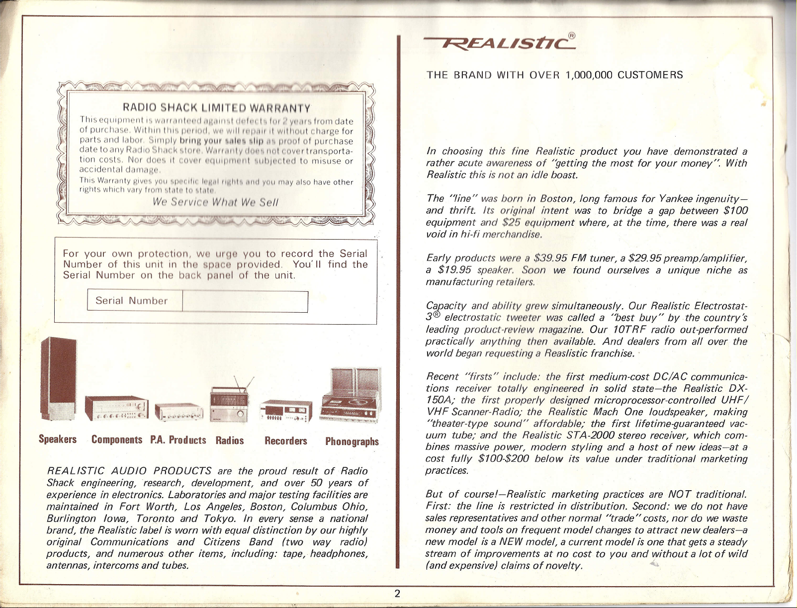
REALISTIC AUDIO PRODUCTS are the proud result of Radio
Shack engineering, research, development, and over 50 years of
experience in electronics. Laboratories and mejor testing facilities are
maintained in Fort Worth, Los Angeles, Boston, Columbus Ohio,
Burlington Iowa, Toronto and Tokyo. In every sense a national
brand, the Realistic label is worn with equal distinction by our highly
original Communications and Citizens Band (two way radio)
products, and numerous other items, includinq: tape, headphones,
antennas, intercoms and tubes.
In choosing this fine Realistic product you have demonstrated a
rather acute awareness of "getting the most for your money:", With
Realistic this is not an idle boast
The "line" was born in Boston, long famous for Yankee
inqenuitv=
and thrift Its original intent was to bridge a gap between $100
equipment and
$25
equipment where, at the time, there was a real
void in hi-ti merchandise.
Early products were a
a
$19.95
speaker, Soon we found ourselves a unique niche as
$39.95
FM tuner, a
$29.95
preamp/amplifier,
manufacturing retailers.
C1Cacity and ability grew simultaneously. Our Realistic Electrostet-
3Relectrostatic tweeter was called a "best buy" by .the country's
leading product-review magazine. Our 10TRF radio out-performed
practically anything then available. And dealers from all over the
world began requesting a Reaslistic franchise ..
Recent "firsts" include: the first medium-cost DC/AC communica-
tions receiver totally engineered in solid state-the Realistic DX-
150A; the first properly designed microprocessor-controlled UHF/
VHF Scanner-Radio; the Realistic Mach One loudspeaker, making
"theater-type sound" affordable; the first lifetime-guaranteed vac-
uum tube; and the Realistic STA-2000 stereo receiver, which com-
bines massive power, modern styling and a host of new ideas-at a
cost fully $100-$200 below its value under traditional marketing
practices.
But of course/-Realistic marketing practices are NOT traditional.
First: the line is restricted in distribution. Second: we do not have
sales representatives and other normal "trade" costs, nor do we waste
money and tools on frequent model changes to attract new dealers-a
new model is a NEW model, a current model is one that gets a steady
stream of improvements at no cost to you and without a lot of wild
(and expensive) claims of novelty. ,,(..
2
)
Page 3
INTRODUCTION
Your new STA-95 is a highly versatile AM/FM Stereo Receiver which
delivers enough power to drive almost any speaker system. The
"honest"
drivo both "main" and "remote" speakers. And it has the perform-
ance an(l convenience features that distinguish a truly great receiver.
• A
•
• FM Multiplex circuit
provides rock-stable storeo separation even with temperatur
changes.
• A linear IC is used in the Phono Preamp to obtain wide dynamic
range and low distortion.
• Tape Dubbing switch allows two-way tape dubbing without
troublesome rear panel connection changes.
sp
njoy
46
watts per channel over the entire audio bandwidth will
s the FM de-emphasis circuits to let you
ts
by using a Dolby N R decoder.
use linear IC's which assure minimum
mbined with high gain.
Is a
Phase Lock Loop IC (PLL-IC) which
S
PJ;jql
AIVIPLI
Audio butputPolllferat no more than
0.3% FetalHarmonic Distortion
into8ohniMftom
Input SensitiytJ:y1,T
Phono,
Phono Overiload
Aux
n
n
rsquencv
1M
Distortiont-:
Signal-to-Noise Ratio', ' .
'M T'U
F
Sensitivity, for 3(i)#dissYN
Capture Ratio
Signal-to-Noise Ratio
Total Harmonic Distortion
Mono ,.' ,
Stereo
Image Rejection
Selectivity
Separation at
F,:,ICATIONS
FI,ER
\ ;7.( 'I
"r' :
j, ,,'~
;L''ii,:'i),i'i.tr:, .
I
t'
··.i
.<";'
?t;:~;;;'l;\
c., ..
1 "'",
pe
I I ,.
I
,,'Jih;
Responser{at, 1 waft)
l
.,
I
lo(.~(;~1
1\:1
ER
I
1'-'·:;
1000
20-20,000
',,!,,, '
L.
,c.,,!,,
'."
lJ,~:','Ii:(. "
1'1
/!
L::i+-21-,4
J
I". ,,"'" /,
i,',_"t-
I'.~ ;
'If
I
Hz
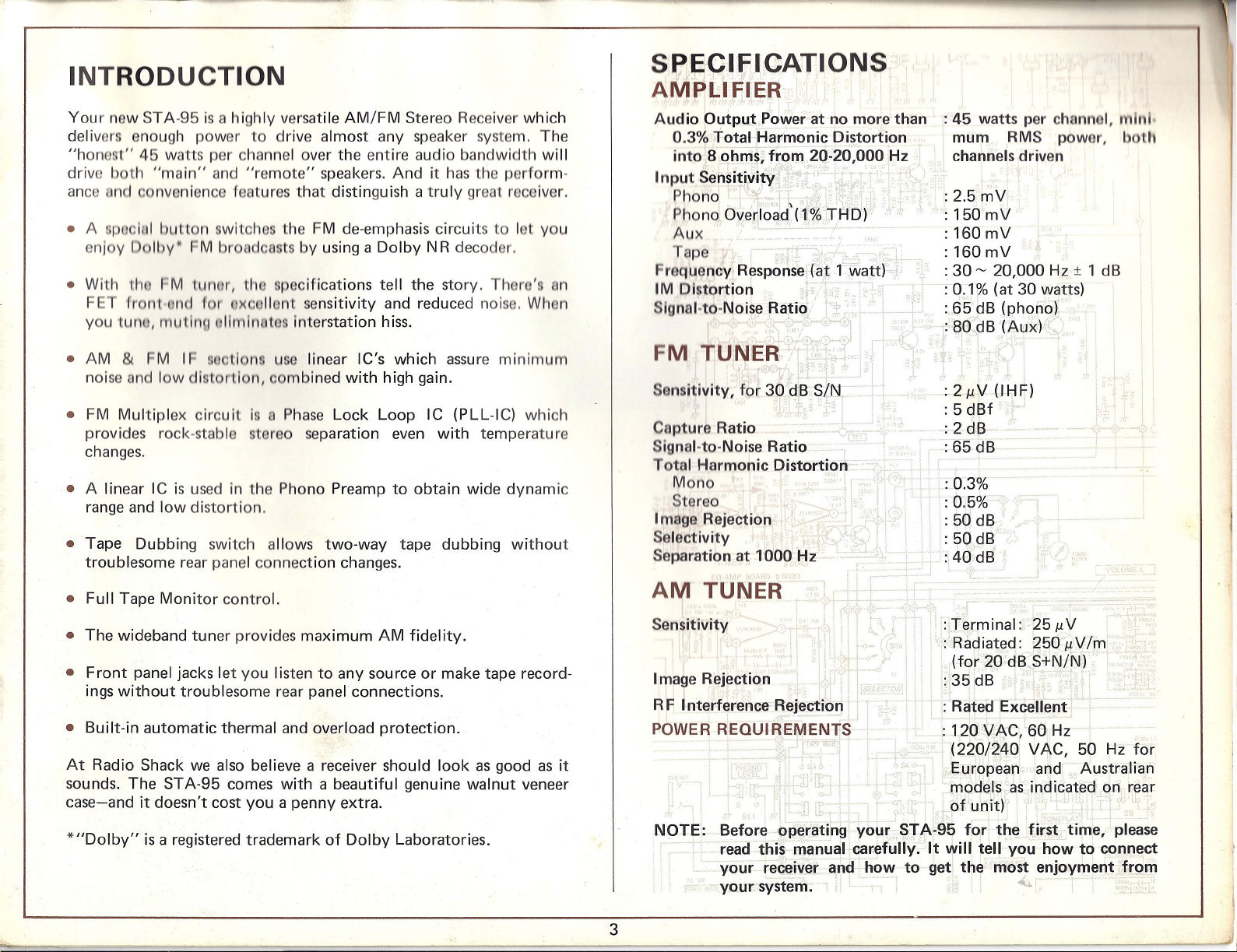
: 45 watts per channel,
,.11111"
mum RMS power, both
Hz
; channels driven
: 2.5mV
:: 150mV
: 160 mV
: 160 mV
: 30~ 20,000 Hz ± 1 dB
:0.1% (at 30 watts)
:,65 .~B(r;>hono)
>HOodB(AllX) .
i·'· ..,.
n
I
: 211V(IHfh
: 5
_1· ,
: 1
dBf
: 2 dB
: 65 dB
:0.3%
:0.5%
: 50
dB
: 50dB
:40dB
• Full Tape Monitor control.
• The wideband tuner provides maximum AM fidelity.
• Front panel jacks let you listen to any source or make tape record-
ings without troublesome rear panel connections.
• Built-in automatic thermal and overload protection.
At Radio Shack we also believe a receiver should look as good as it
sounds. The STA-95 comes with a beautiful genuine walnut veneer
case-and it doesn't cost you a penny extra.
*"Dolby" is a registered trademark of Dolby Laboratories.
AM TUNER
Sensitivity
Irnaqe Rejection
RF Interference Rejection
POWER R'EQUIREI\iIENTS
NOTE:
3
Beforebp'erating your STA~95
read this manualcarefully. It will tell you how to connect
your receiver and' how to get, the' most enjoymentfro,m
your system. ., ~
:Terminal: 2511V
:'Radiated: 250 I1V
1m
(for 20 dB S+N/N)
:35idB
RC!1eaExcellent
.:120 VAC,'60 Hz
:(22.Q/240
VAC, 50 Hz for
.Eu~()pea!1.arid Australian
):
models. as indicated on rear
of unit)'
for
the .~irs.t. time, please
Page 4
II
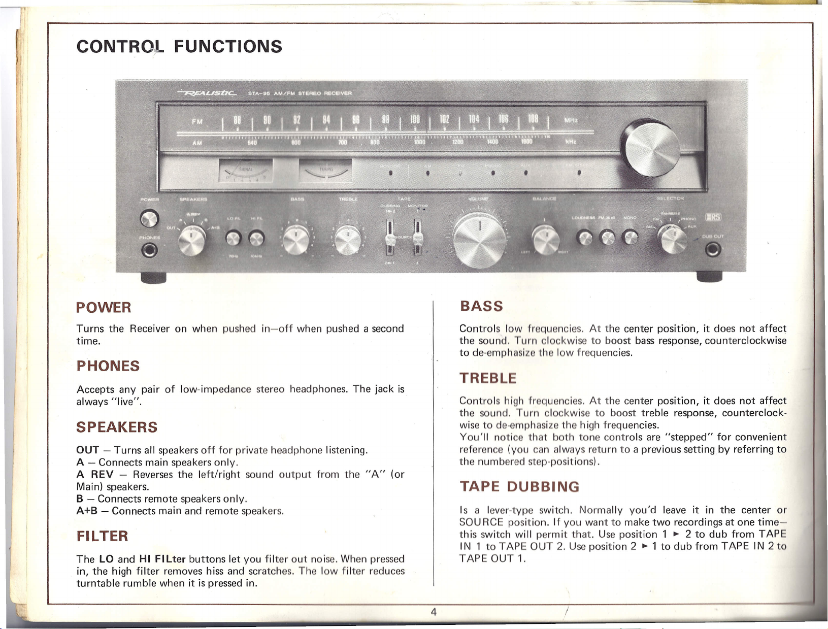
CONTRo,L FUNCTIONS
POWER
Turns the Receiver on when pushed in-off when pushed a second
time.
PHONES
Accepts any pair of low-impedance stereo headphones. The jack is
always "live".
SPEAKERS
OUT - Turns all speakers off for private headphone listening.
A - Connects main speakers only.
A REV - Reverses the left/right sou nd output from the "A" (or
Main) speakers.
B - Connects remote speakers only.
A+B - Connects main and remote speakers.
Fll TER
The LO and
in, the high filter removes hiss and scratches. The low filter reduces
turntable rumble when it is pressed in.
HI
Filter buttons let you filter out noise. When pressed
BASS
Controls low froquencles. At the center position, it does not affect
the sound. Turn clockwise to boost bass response, counterclockwise
to de-emphasize the low frequencies.
TREBLE
Controls high frequencies. At the center position, it does not affect
the sound. Turn clockwise to boost treble response, counterclock-
wise to de-emphasize the high frequencies.
You'll notice that both tone controls are "stepped" for convenient
reference (you can always return to a previous setting by referring to
the numbered step-positions).
TAPE DUBBING
Is a lever-type switch. Normally you'd leave it in the center or
SOU RCE position. If you want to make two recordings at one time-
th is switch wi II perm it that. Use position 1 ~ 2 to dub from TAP
IN 1 to TAPE OUT 2. Use position 2 ~ 1 to dub from TAPE IN 2 t
TAPE OUT 1.
4
Page 5
MONITA
VOLUME -
und lovo: 'for both channels-from minimum to maximum,
adjust for desired level of sound. It
UIIII,
you
1",pouillol).
ndlllllill III
SELECTOR
hooses one of five input positions.
AM - Activates the built-in wideband AM tuner.
M - Activates the built-in FM tuner.
M MUTE - Activates the built-in FM tuner and eliminates inter-
tnrlon
hiss.
PHONO - For any turntable equipped with a magnetic cartridge.
BALANCE -
twoon channels. At the center position (you'll feel a slight
thesound will be equal from both channels.
use to provide best stereo balance of
sOllnd
"cntch"},
I
LOUDNESS
When pushed in, the switch introduces a special low and hllll!
frequency emphasis into the amplifier circuitry. LOUDNESS on
hances the sound quality at low volume levels by boosting bass and
treble frequencies which the human ear does not hear as well asth
mid-range frequencies. Use the switch position which provides th
most pleasing sound reproduction.
FM 25pS
Makes your Receiver "Dolby FM-compatible". By adding a Dolby
noise reduction decoder or a Dolby tape deck, you can get the
full benefit from superb Dolby FM broadcasts. (Check your local
FM stations to see if any of them offer Dolby broadcasts.)
When listening to a non-Dolby FM (or if you do not have a Dolby
decoder), leave FM 25 J.lSbutton in out position.
MONO
I\UX -
For any high-output source-a second tuner, a crystal or
mlc phono cartridge, a second tape deck, TV, Ham radio, etc.
UB OUT
toreo phone jack serves as an extra tape output. This makes
y to copy tapes or record any program source without changing
r-panel connections. The output should be connected to the
rdor's Auxiliary or Line inputs.
Tuning Knob
unos AM and FM stations.
TUNING Meters
he left meter is for FM and AM signal strength indication; tune
for maximum deflection. The right meter functions on FM only-
this is an FM "Center Tuning" meter.
FM STEREO Indicator
This bright red LED lightsup when the MONO button is out and you
are tuned to a stereo FM signal.
When pressed in, switches the amplifier and tuner from stereo to
monaural operation. In the out position, the amplifier operates in
stereo and the FM tuner automatically switches to stereo when there
is a stereo signaI.
Function LED's These bright red LED's light up to indicate the
function you are using-AUX, PHONO, AM, FM or FM MUTE.
TAPE MONITOR Indicator - This bright green LED lights up when
TAPE MONITOR switch is in the 1 or 2 position.
'"
5.
Page 6

=-
+--
-----t:::
-----~
0)
•...
00
•...
~ It)
-----~
+--
_____ N
"'------
~ o
-----0)
•...
•...
M
•...
•...
•...
•...
•...
00
•....
c.o
..J
W
Z
~
a:
<C
w
a:
CD
It)
~
M
N
•...
Page 7

1. Built-in adjustable ferrite AM antenna - is adequate for most
areas for AM reception. Swing down and move around 'for best
reception.
11. TAPE MONITOR 2 IN - Accepts output from a s
deck or recorder for tape playback. These jacks ar
'front panel TAPE MON ITOR Switch is set to 2.
2. AM ANTenna Screw Terminal - Connect an external AM/
short-wave antenna to this screw for long-distance AM rocep-
tion. In most areas the built-in antenna will provido oxcollont
reception.
3. FM ANTenna 300n Screw Terminals - Connect
usina standard 300-ohm lead-in to these screws.
4. FM Line Cord Antenna - Connect to the 300n FM s
minal illustrated to provide FM reception in most metr
areas. Disconnect the line cord antenna when using an
FM antenna.
5. FM ANTenna 75n Screw Terminals - Connect to antenna
75-ohm coaxial lead-in. Coaxial cable provides extremely 1111111
resistance to static and other noise.
6. PHONO GND - Accepts the green or black ground wire found
on most turntables. Making this "ground" connection redu
or eliminates hum.
7. PHONO - Accepts output from any turntable equipped with
magnetic cartridge. These jacks are active when SE LECTO R is
set to PHONO.
nntunn
lHlIll(l
· TAPE MONITOR 2 OUT - Permits recording with a second
tape recorder. Also use for duplicating (or Dubbing) tapes being
played through the Amplifier from another Recorder/Player
nnectedtoTAPE MONITOR 11N.
· A SPEAKERS Screw Terminals - Powers main speakers which
10
not have phono jack connectors.
NOTE: Use either phono jack or screw terminals for A speakers,
not both.
14. A SPEAKERS Phono Jacks - Connects to speakers with phono
jock connectors.
NOTE: Use either phono jacks or screwterminals for A speakers,
not both.
· B SPEAKERS Screw Terminals - Powers remote speakers.
· SWITCHED Convenience Outlet - Plug in an audio accessory
which you want turned on and off by the front panel POWER
switch. For example, connect a Tuner to this receptacle; thus,
when you turn the Receiver on and off, the Tuner will auto-
matically be turned on and off at the same time. Power drawn
from th is receptacle shou Id not exceed 100 watts.
8. AUX - Accepts output from any high-level source-a second
tape deck or tuner, a ceramic or crystal phono cartridge, etc.
These jacks are active when SE LECTO R is set to AUX.
9. TAPE MONITOR 1 IN - Accepts output from any tape deck or
recorder for tape playback.
These jacks are active when front panel TAPE MONITOR
Switch is set to 1.
10. TAPE MONITOR 1 OUT - Permits tape recording any source
chosen by the SELECTOR switch. The output from these
jacks is unaffected by the front panel controls. Also use for
duplicating (or Dubbing) tapes being played through the Am-
plifier from another Recorder/Player connected to TAPE
MONITOR 2 IN.
· POWER FUSE - Protects the Receiver from voltage surges,
short circuits and other abnormal operating conditions. If the
dial lights do not go on when POWER is on, check the fuse. If
it is blown, replace it with an identical size and value (3.5A).
18. UNSWITCHED Convenience Outlet - Powers any audio ac-
cessory up to 200 watts. The front panel POWER switch does
not affect this receptacle.
19. AC Cord - Supplies the Receiver's power. Plug the cord into
any 120 VAC, 60 Hz outlet (220/240 VAC, 50 Hz power where
the sets are so marked on the rear for European and Australian
models).
""
7
Page 8

CONNECTIONS
BEFORE MAKING CONNECTION
1. Do not plug in the Receiver's power cord,
2. Be sure POWER is off.
If you are using 4 ohm speakers, connect only one set of speakers, or
use only one set of speakers at a time. That is, don't useA+B if one
set is 4 ohms. Low impedance speaker systems will tend to trip the
automatic circuit protection/amplifier shut-down circuitry when
operating at high volume levels (to prevent damage from amplifier
overdrive) .
NOTE: To reduce hum, use shioldod nudlo
tions except speakers.
011111011
for all connec-
SPEAKERS
The STA-95 has two sets of A (main) speaker outputs - use only one
set. If your speakers have phono plug inputs, use the Receiver's
phono plug outputs and a set of unshielded speaker cables. Otherwise
use the Receiver's screw terminal outputs.
For maximum bass response, be sure to observe proper phasing.
Connect the + Receiver speaker output to the speaker terminal
labeled A, 1 or +; and the - output to the speaker terminal labeled B,
2 or -. Most speaker wire is marked with a ridge along one conductor
or has one color-coded conductor. If you use preassembled phono
plugs, phasing will automatically be correct.
Connect B (remote) speakers following the instructions above. Be
sure the speakers are phased properly.
NOTES: 1. The STA-95's outputs are designed for 4-16 ohm
speakers. However, when more than one set of speakers
is being connected, use only 8-16 ohm systems. This
will prevent the amplifier from being overloaded.
2. When using the screw terminals, be sure no stray
strands of wire touch a second term inal or the chassis-
a harmful short could result.
3. Connect no more than two sets of speakers to the
receiver.
4. Use only as much wire as necessary to connect the
speakers.
TURNTABLE
Connect the turntable leads to the PHONO inputs. If the turntable
has a ground wire (usually green or black), connect it to the PHONO
GND screw. Plug the turntable's power cord into an AC outlet or the
Receiver's UNSWITCHED convenience outlet.
(NOTE: If the turntable has a ceramic or crystal cartridge, connect it
to the AUX jacks.)
TAPE DECK
For recording, connect the Receiver's TAPE MONITOR 1 OUT
jacks to a Recorder's AUX or Line Input. For playback, connect the
deck's PRE AMP Output or Line Out jacks to the Receiver's TAPE
MONITOR 1 IN jacks. You can Connect a.second deck to the TAPE
MONITOR 2 IN/OUT jacks.
For playback only, you can connect a 3rd deck to the AUX jacks
(assuming you are not already using them).
ANTENNAS
Be sure the line cord FM antenna is connected to the FM ANT 300n
terminal. The built-in AM antenna requires no attention.
If you think you need an external antenna, see HINTS FOR BETTER
SOUND.
AUXILIARY
Plug the output from any high level source into the AUX jacks. This
input is ideal for a second tuner, TV audio, ceramic or crystal phono
cartridges, a tape player, shortwave radio, etc ...(.. .
8
Page 9

TYPICAL STA-95 SYSTEM
75 ohm
ANTENNA
(OUTSIOEI
1-----
\
L__
DOLBY NR DECOOl~n
]
II11I
IIIII!.
11111:
'(
tlm1UU!1I
\ I
llllim
N-tl-t
SPEAKERS
AI
r
I
I'
I
11
11
o
; \::.I
I~:~
TURNTABLE
---------
-
c=:::Jol
'=!!!!!!!!!!<==:=''''':==IJI[D
"TO PREVENT ELECTRIC SllbCI(,noNUl
REMOVECOVER1DRBAClO.M)~S{l\srnVltl
-ABlE PARTS INSIDE.
'\
TO
ACT
/
..
QUALIFIED
t
I I I «1)
CAUTION
RUERSERV'5ilU
SERVICE
Pi SONNI
•••.., TAP MONITOR. IAN
IN
o
s.",., ~
r.~WJt
I10V 60H,
UMS:WW'....
'
..
,,,'
'
.....
MHIiII~ I
our
IN PUI
r
:,n'~K'
:~r-'-I
\ ~L!
fIIS(JMf"t •.••~:
_,,/
ACI20V60fll
,'1
: ft
1
.~
• TOAC
STEREO
CASSETTE DECK
/
.(.
9
Page 10

CHOOSING THE REST 0
~YS
M
SPEAKERS
No stereo system sounds
speakers, so choose th
afford for your main sp
Of course there are a wide variety of speakers intended primarily for
remote use. Some are weather-proofed for outdoor installations and
others offer the convenience of a built-in volume control. Naturally,
if you plan to use your remote speakers for critical listening, you
should consider using the same type of speakers for both your main
and remote installations.
TAPE DECKS
Until very recently, reel-to-reel tape decks were the only possible
choice for those interested in true high-fidelity. Recent technological
advances have made
sou nd qual ity of
Reel-to-reel decks are a must for those who want to edit their own
tapes and they still have marginally the best performance.
The best cassette docks, equ ipped with special tape bias settings and
noise reduction circuitry, will out-perform many reel-to-reel decks.
They have the additional advantage of compactness and convenient
pop-in loading. In addition, cassettes can be used in the car as well as
at home.
In addition, an 8-track cartridge uses a continuous tape loop wh ich
can provide hours of uninterrupted music. Many 8-track playback
decks are less expensive than record changers and let you use car
tapes at home.
a-rrsck
root-to-reel
and cassette recorders approach the
mach ines.
slightly less fidelity than cassettes or reels,
s. An 8-track recorder plays pre-recorded
n save money by recording new auto tapes.
Your nearest Radio Shack has a complete selection of speakers for
every application and budget.
TURNTABLE
For convenience, most people prefer a record changer (often called
an automatic turntable) to a manual turntable. A changer will play
an entire stack of records and returns the tonearm to its rest at the
end of the last record.
For the best sound, your turntable should be equipped with a
magnetic cartridge. Cartridges equipped with conical styli (needles)
are usually inexpensive and have good sound. But a cartridge with an
elliptical stylus follows the record groove more accurately and, so,
produces better sound. Your Radio Shack store has a selection of
changer systems which come with factory-mounted bases and car-
tridges.
HEADPHONES
Any system can benefit from a good pair of stereo headphones. They
provide convenient private listening and many people find the
heightened stereo very exciting.
Your STA-95's front-panel headphone jack will accept any low
impedance stereo headphones. When shopping, wear each pair of
headphones long enough to be sure they will be comfortable.
ANTENNAS
Under most conditions your receiver's built-in antennas should
provide adequate AM and FM reception. If you have difficulty see
HINTS FOR BETTER SOUND.
..(.
10
Page 11

BEFORE PLUGGING IN THE
STA-95'
SELECTOR
1.
Double-check all connections - especially the speaker connec-
tions-to assure that all connections are firm and that there are
no shorts.
2. Set the VOLUME control to minimum.
3. All pushbuttons should be out.
OPERATING THE STA-95
SPEAKERS/HEADPHONES
Select any speaker or combination of speakers with the SPEAKE RS
switch. In the A position, the Receiver's power goes to the main
speakers only and in theBposition to the remote speakers only. A
B puts the same stereo signal through both sets of speakers. In the A
REV position, the left/right sound output from the A/Main speakers
will be reversed. Sometimes this reversing of channels can give
interesting effects from various sound sources.
The PHONES jack permits headphone listening with any or all of the
speakers. For private listening, turn the SPEAKERS switch to OUT.
hoose the input you want by turning the SELECTOR switch.
AM - Use the Tuning knob to select a station. Tune for the
highest reading of the SIGNAL meter. Adjust the front-panel
ntrols for best sound.
M - Use the Tuning knob to select a station. Tune for the
1'110hostreading of the SIGNAL meter and rotate tuning knob
until TUNING meter is at null or center position. If the station is
broadcasting stereo, FM STEREO LED will light up. Adjust the
rent-panel controls for best sound.
I
r
tile
signal is noisy, try either or both of these solutions:
l.
Press the HI Filter button. (This will filter out some treble, but
signal will still be stereo.)
s the MONO button. (This will leave the fidelity unimpaired,
but the signal will no longer be stereo.)
M MUTE - Use as FM (above), but a special circuit eliminates
Intorstation hiss. When listening to very weak stations, it may be
necessary to set the SELECTOR to FM.
PHONO - Put on a record and adjust the front-panel controls for
best sound.
AUX - Adjust VOLUME, BASS and TREBLE for best sound.
POWER
Press POWER button in to turn the Receiver on. Pressa second time
to turn the Receiver off.
VOLUME
Adjust VOLUME for a pleasant listening level.
BALANCE
Adjust for best stereo sound. Normally this will be at the center
position of this control. However, depending on your speakers, the
program source and/or your listening position, you may find that
other settings provide better stereo sound. Adjust as you see fit.
11
NOTE: If the TAPE MONITOR switch is in the1or 2 position, the
SELECTOR switch will have no effect on the sound. The
MONITOR LED will light up to remind you that TAPE
MONITOR is being used.
TAPE
Playback - Regardless of the input SELECTOR position, set the
TAPE MONITOR switch to the appropriate position (if your Tape
Deck is connected to TAPE MONITOR
TAPE MONITOR switch to1position; if connections are to "2",
use 2 position). When you have finished listening to the- tape, set
the TAPE MON ITOR switch to SOU RCE position.
1
IN and OUT, set the
Page 12

REBLE
ting a tape) - Your
flnn/Plllyhuol< olrcults built-in. Connect the
IN and OUT; connect
nd OUT.
Now, if you wont
the TAPE DU
of your now
to 2 position
Deck has 3·h
With these same connections, you can make dubbings in the reverse
way with the "master" tape on 2nd Tape Deck, set the TAPE DUBB-
ING switch to 2 ~1position. Then you can set the TAPE MONITOR
switch to position
Deck connected to
t
1
to hear the new recording (assuming the Tape
"1"
has 3-head Tape Monitoring feature).
" tape and duplicate it - set
position; to check the quality
he
TAPE MaN ITOR switch
ding (assuming the 2nd Tape
ture) .
urn the TREBLE control toward
toward "-" to oe-ornphaslzo thorn. In the center position, the control
has no effect on
'1:1'10
sound.
"+"
to boost high frequencies or
LOUDNESS
Press in the LOUDNESS button-the bass and treble are boosted to
compensate for tho ear's reduced sensitivity at low listening levels.
In the normal (out) position, there is no loudness compensation in
lume level.
FM 25#S
For normal FM IIstol1lng, loave FM 2511S button out. If you want to
record a signal bolng broadcast by an FM station using Dolby NR
system, press this button in. Then, when you play back the tape,
you must use a Dolby Decoder (that is, record with a Dolby-type
tape recorder, but withDolby circuit "off"; then play back with
the Tape Deck's Dolby circuitry "on"). If you press the FM 2511S
button in when Iistoning to a Dolby FM signal, its sound will be
excessively "bright" (too much high-frequency emphasis).
If you have a Dolby NRDocoder, you can connect it to the TAPE
MONITOR
the1position. When an FM station is broadcasting a Dolbyized FM
signal, you will enjoy the following advantages (with a Dolby NR
Decoder) :
1
IN/OUT jacks and set the TAPE MONITOR switch to
Filters
The LO and HI Filters elim inate noise on any program source. The
HI
FILter removes FM hiss and record noise while the LO Filter re-
duces turntable rumble. Both filters are activated when pressed in.
BASS
Turn the BASS control toward
toward
has no effect on the sound.
«:»
to de-emphasize them. In the center position, the control
"+"
to boost the low frequencies or
• Improved signal-to-noise ratio
• Full program dynamic range, even at high frequencies
• Improved reception in weak-signal areas
MONO
Press the MONO button to defeat normal stereo operation. The
resuIt is a composite signal (left + right). When you Iisten to weak
FM stereo stations, pressing the MONO button will reduce the hiss,
but the signal will no longer be stereo.
~
12
Page 13

...."
HINTS FOR
BETTER SOUND
POSITIONING YOUR SPEAKERS
Where you put your speakers is a highly personal matter, depending
largely on the arrangement of your listening room and the way you
listen to music. Where you put your speakers does make a difference
in how your system will sound, so before settling on a final arrange-
ment, try several alternatives.
Bass response is highly dependent on speaker location. For maximum
bass, place the speakers in the corners of your room. Putting th
speakers directly on the 'floor will make the bass even stronger. If th
bass sounds boomy and exaggerated, move the speakers away from
the corner slightly, pull them out from the wall a little or raise them
6 to 18 inches (15 - 45 cm) off the floor.
Stereo
Stereo speakers should be 6 to 8 feet (1.8 - 2.4 m] apart. Putting
them too close together reduces the stereo effect, while placing them
too far apart reduces bass response and creates a "hole in the
middle". Also, most speakers have a tweeter dispersion angle of
about 60°. Ideally your listening position should be in the overlap, so
you may want to angle the speakers slightly toward you for better
stereo.
I.
SOLDER
4FT,8IN(142cm)
II. ANTENNA LEAD-IN
·1
SOLDER
ANY LENGTH
A set of VH F-TV rabbit ears or ones made specially for FM reception
work well in suburban areas. Some deluxe models feature electronic
"tuning" for better directionality. Connect such antennas to the
300n terminals.
0.315' 0119- 0.394"
(I~
ANTENNAS
Under most conditions your STA-95's built-in antennas should be
adequate for AM and FM reception. If you are not satisfied with the
reception, try one of the arrangements listed below.
For FM, build the low-cost folded dipole (illustrated); or buy one
ready-made from Radio Shack (42-2385). Just splice regular 300-
ohm lead-in wire as shown. Apply a small amount of solder and
heat the twisted ends until solder flows evenly over each strand of
wire. Attach the lead-in to the 300n terminals on the back of the
receiver. The antenna itself can be tacked to the back of a record
cabinet or onto a wall-the higher the better.
13
SHIELD CONDUCTOR
~~.,y, :
75-ohm coaxial lead-in
~
/L-
Page 14

An outside VH F-TV antenna provides
inexpensive "sp Iitter " perm its you t
Receiver to the same antenna. In 'fring
NOTE: To protect your R
outdoor antenna.
lightning arrestor on any
CARING FOR THE STA-95
The ST A-95's genuine walnut case looks best when it is polished
occasionally with lemon oil. Waxing produces a glossier finish, but
can eventually cause a dull wax buildup.
Clean the metal parts of the front panel and the dial face with a soft,
damp cloth (do not use abrasives or solvents).
Thermal Protection
Your Receiver also has built-in thermal overload protection. That
means that it can not become abnormally hot and damage some
portion of the circuitry. If internal temperatures do rise abnormally,
the Receiver will automatically silence itself. If this happens, check
to be sure you have not placed something over the ventilation
holes-if you have, remove it. If you are using speakers with exces-
sively low impedance, the amplifier circuit may be over-driven and
thus producing excessive heat. This can be caused by using 4-ohm
speakers on main and remote-if you use remote with main speakers,
be sure to use either 8 or 16 ohm speakers.
In any case, if the Roceiver does turn itself off, set POWE R to off,
check ventilation and then check to be sure your speakers are proper-
ly connected and that you are not using a combination of 4-ohm
speakers for both main and remote. The protective circuit is triggered
by temperature, thus it may take a few minutes for the circuitry to
cool down and allow the unit to come back on. If everything is OK,
turn power back on. If 'the Receiver does not come back on, you
may have to wait a few more minutes for everything to cool
adequately-it should never take more than about 20 - 30 minutes
for this cool-down cycle. If Receiver still does not come on, check
the fuse (3.5A) on the rear panel. Replace only with the same size
and rating.
Overload Protection
We've built-in an important protection circuit-which protects the
Receiver from overload. If too much current flows in the output
circuit (from excessively low impedance [combinations less than 4
ohms] , shorted speaker terminals, etc.) a protection circuit activates
immediately and the output drops. In such a case, carefully check
the output connections and the speaker impedance (don't use 4-ohm
speakers if you use more than one pair).
1
""
14
Page 15

s
<C
a:
C!)
<C
-
c
o
-
~
~
w
J:
o
tJ)
I
~~i}!--~-
'
~-;:j
I
' .~
,!
I
I
S~ _
$i-
.~
~
-~
----"
-¢--------!.-_II
.
if
L ~
[1
I~I ~~
1~1~!-
",
If 1
0 •
L~
!
i
;
61
LO
I
~~~H
I~~~
I
I
'~<":i
-I
-c:iZ''''----'=:':-+---=O~.Lo;~
~
'
I
I
I
Page 16

MACH
ONE
SPEAKERS - FOR T
TM
MUSIC MINDED
find
today wa oro
poakers. Whether you are looking
l-wcoc piece of furniture that sound
ood or just a small bookshelf-type.
verything from our big sound Mach
to our Sophisticated Optimus Tower to our
handsome Minimus-S.
THE
place to go for
f
On
OPTlMUS(!) SERIES
NOVA®
SERIES
MINIMUS®
SERIES
'.
.,.,-'
:'c.:RADIO
SHACK ~ A DIVISION
3AS' ~ . .
. RYOALMERE. N.SW. 21i6 5140 NANINNE WEST MIOLANDS WSlO
.OF
TANDY CORPORATION·U.S.A.:FORT WORTH. TEXAS 76102·CANADA: BARRIE. ONTARIO.l4M 4W5
":,_ Printed
.\~~~
AUSTRALIA BElGIUM U. K.
280-316 VICTORIA ROAO PARC INOUSTRIEl DE NANINNE BILSTON ROAO WEONESBURY
~EALIShc::..
-::v<
7JN
~
in Japan
 Loading...