

Real Flame G9-2-24-12M, G9-2-24-12P, RD9-2-20, RD9-2-24, RD9-2-30 Owner's Manual
...
OWNER’S
MANUAL
Burner Systems:
G9-2-24-12(M)(P)
Log Sets:
RD9-2-(20,24,30) Golden Oak Designer
S9-2-(20,24,30) Split Oak
G9-2 (SEE THRU) SERIES UNVENTED GAS LOG SETS
INSTALLER: Leave this manual with the appliance
CONSUMER: Retain this manual for future reference
Installation and service must be performed
by a qualifi ed professional installer, service
agency, or the gas supplier.
WARNING: If the information in this
manual is not followed exactly, a fi re or
explosion may result, causing property
damage, personal injury, or loss of life.
DESIGN CERTIFIED
to standards:
Unvented Room Heater
ANSI Z21.11.2-2007
and
Vented Decorative Appliance
ANSI Z21.60b-2004
Important
Read these instructions carefully and completely
before starting installation of the burner system.
This appliance may be installed in an
aftermarket, permanently located,
manufactured (mobile) home where not
prohibited by local codes.
This appliance is only for use with the type of
gas indicated on the rating plate. This appliance
is not convertible for use with other gasses.
Do not store or use gasoline or other
fl ammable vapors and liquids in the vicinity
of this or any other appliance.
WHAT TO DO IF YOU SMELL GAS:
• Open a window.
• Do not try to light any appliance.
• Do not touch any electrical switch; do
not use any phone in your building.
• Immediately call your gas supplier from
a neighbor’s phone. Follow the gas
supplier’s instructions.
• If you cannot reach your gas supplier,
call the fi re department.
It is imperative that you maintain
your unvented gas appliance by
having it cleaned and serviced
regularly. See pages 11, 20 & 21
for details.
This is an UNVENTED gas-fired heater. It
uses air (oxygen) from the room in which it is
installed. Provisions for adequate combustion
and ventilation air MUST be provided. See
section entitled VENTILATION AND CONFINED
SPACE INFORMATION.
This appliance is designed as an attended
appliance. Adults must be present when the unit
is operating. Do not leave this unit burning when
unattended or while anyone is sleeping.
Installation, service, and the provisions for combustion
and ventilation air MUST conform with local codes
and with the
National Fuel Gas Code, ANSI Z223.1/
NFPA 54, or the CSA B149.1, Natural Gas And
Propane Installation Code.
254-L-08c-4
ROBERT H. PETERSON CO. • 14724 East Proctor Avenue, City of Industry, CA 91746
REV 7 - 1102030901
1
L-F2-083

CONTENTS
2 CONTENTS
3 SPECIFICATIONS AND REQUIREMENTS
4 IMPORTANT SAFETY INFORMATION
5 VENTILATION AND CONFINED SPACE SAFETY INFORMATION
6 MINIMUM CLEARANCES TO COMBUSTIBLES
8 PRE-INSTALLATION AND FIREPLACE PREPARATION SAFETY
9 INSTALLATION SAFETY INFORMATION
9 INSTALLATION SAFETY GUIDELINES
10 OPERATIONAL SAFETY INFORMATION
11 CLEANING AND SERVICING IMPORTANT INFORMATION
12 INSTALLATION - CONNECTING THE GAS TO THE BURNER SYSTEM
12 WHEN USED AS A VENTED DECORATIVE APPLIANCE (PER ANSI Z21.60b-2004)
13 LOGS - PARTS LIST
14 BURNER PARTS LIST FOR MILLIVOLT VALVE
15 CONNECTING THE GAS TO THE BURNER SYSTEM
15 ATTACH BURNER PLATE TO THE FLOOR
16 CHECKING GAS PRESSURE
17 GLOWING EMBER PLACEMENT
17 GLOWING EMBER AND LOG PLACEMENT
19 DAMPER CLAMP INSTRUCTIONS (IF APPLICABLE)
20 CLEANING AND SERVICING
21 TO CLEAN THE LOG SET
21 CLEANING AND SERVICING THE ODS PILOT
22 CHECKING THE ODS PILOT FLAME APPEARANCE
22 OPERATING THE UNVENTED GAS LOG SET
23 LIGHTING INSTRUCTIONS - SERIES 12 VALVE
24 LOG SET NOTES PAGE
25 TROUBLESHOOTING
28 WARRANTY
REV 7 - 1102030901
2
L-F2-083
SPECIFICATIONS AND REQUIREMENTS
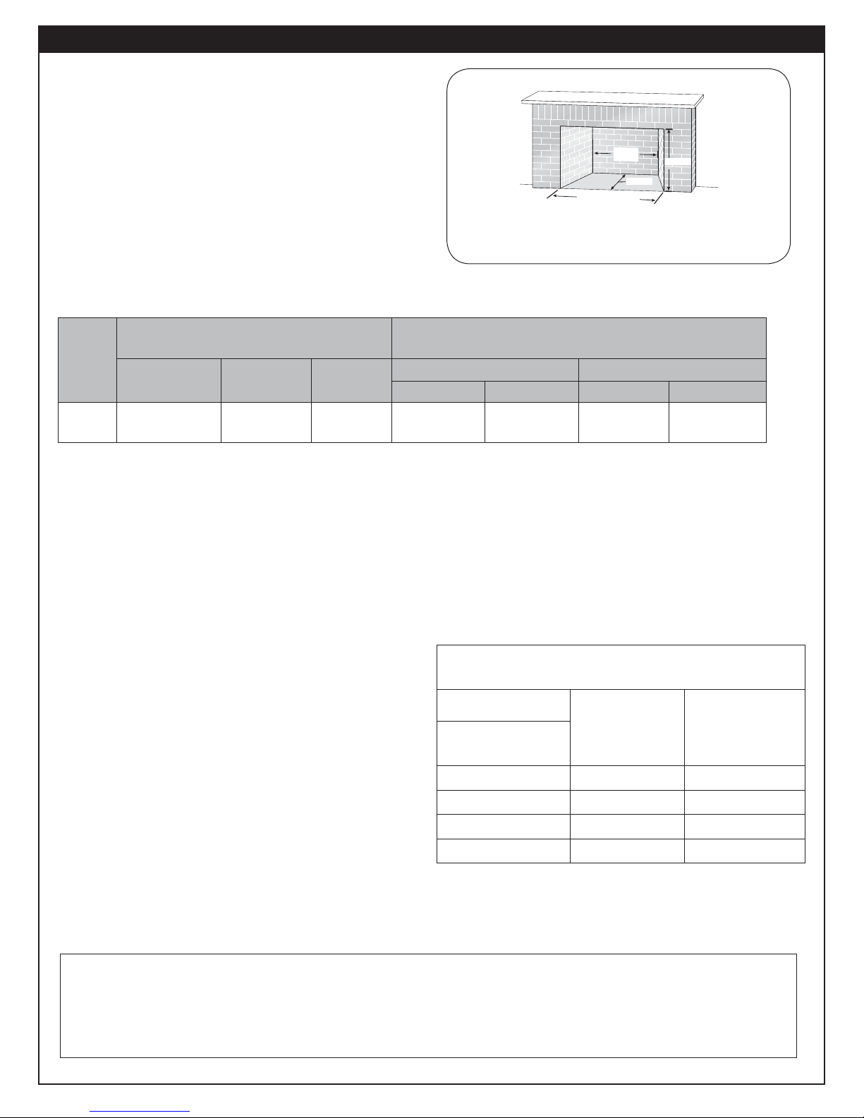
DEPTH
HEIGHT
FR ONT
WIDTH OPENING
Rear
width
Height
Front
width opening
Depth
WARNING: This appliance is for installation only in a:
1. Solid-fuel-burning masonry or UL-127
factory-built fi replace, or
2. Listed ventless fi rebox enclosure.
It has been designed certifi ed for these installations.
Exception: DO NOT install this appliance in a factory built
fi replace that includes instructions stating it has not been
tested or should not be used with unvented gas logs.
Note: Installation in any other fi replace is prohibited and
will void any approvals and warranties.
Any installation of this appliance is subject to minimum fi replace size requirements below:
Fireplace Dimensions
3-1
Fig.
Log
Minimum Fireplace Size (refer to Fig.
3-1)
Set
Size
24"
* based on minimum depth
G9-2 Series vent-free gas log sets are available with
a variable fl ame-height control valve that can be used
with the optional remote transmitter and receiver.
A spark ignition system (piezo) allows the gas pilot to be
lit without the use of matches, and permits the operation
of the appliance during a power outage.
This burner system is equipped with an Oxygen
Depletion Sensor (ODS) safety pilot system. The ODS
senses the amount of oxygen available in the room and
shuts the burner system off before the oxygen level
drops below 18%. The pilot can only be relit when fresh
air is available. This may require opening a window
or a door to another room or cracking the damper
open slightly.
This gas log set has been certifi ed to two standards:
UNVENTED ROOM HEATER-ANSI Z21.11.2-2007
VENTED DECORATIVE APPLIANCE-ANSI Z21.60b-2004
Check local or state codes to determine if vent-free
heaters are permitted in your area before you install
this log set as a vent-free appliance. If not permitted,
you may install and operate this log set as a vented
appliance.
Width Depth Height
28" front
28" rear *
18" 18" 39k 39k 19k 26k
Nat. gas L.P. gas Nat. gas L.P. gas
BTU Input Rating
High Setting Low Setting
This unit may not be installed in a vented fi replace with
a chimney of less than 15 feet in height.
Observing minimum fi replace dimensions and centering
the appliance in the fi replace will ensure adequate
clearance for operation and servicing. It may be
necessary to disconnect the unit for some types of
service.
Minimum Permanent Chimney Vent Opening
in sq. in. (when used as a vented appliance)
Table 3-1
Chimney
Height
15'
20'
25'
30'
Factory
built
fi replaces
25 29
22 26
21 -
20 24
Masonry built
fi replaces
Important: For safe operation and proper performance of this product and to comply with certifi cation, listings,
and building code acceptances, use ONLY Peterson Real-Fyre® controls, parts, and accessories
that have been specifi cally listed or certifi ed for use with this burner system. Use of other controls,
parts, or accessories is prohibited and will void all warranties, certifi cations, listings, and building
code approvals, and may cause property damage, personal injury, and loss of life.
REV 7 - 1102030901
3
L-F2-083

IMPORTANT SAFETY INFORMATION
ANSI Z21.11.2-2007 UNVENTED ROOM HEATER GENERAL SAFETY INFORMATION
A. WARNING: CARBON MONOXIDE POISONING MAY LEAD TO DEATH.
When used without fresh air, gas appliances may give off carbon monoxide, an odorless,
colorless, poisonous gas. Early signs of carbon monoxide poisoning are similar to the fl u, with
headaches, dizziness, and/or nausea. If you have these signs, the gas appliance may not be
installed correctly, or may not be working properly. GET FRESH AIR AT ONCE! STOP USING THE
APPLIANCE IMMEDIATELY! Have the appliance serviced before use continues. Some people,
including pregnant women; persons with heart or lung disease, asthma, or anemia; those under
the infl uence of alcohol; and persons at high altitudes, are more affected by carbon monoxide
than others.
If there are ANY signs of carbon monoxide, GET FRESH AIR AT ONCE! STOP USING THIS
APPLIANCE IMMEDIATELY!
B. If any soot appears on the appliance or other areas of the fi replace in which this appliance is
installed, shut system off and call a qualifi ed professional service technician, vent-free gas
burner system technician, or your local gas company.
C. This appliance may be installed in an aftermarket, permanently located, manufactured (mobile)
home where not prohibited by local codes. Installation of appliances designed for manufactured
homes or mobile homes must conform with the Manufactured Home Construction and Safety
Standard, Title 24 CFR, Part 3280 in the U.S.; or with CAN/CSA Z240 MH, Mobile Housing in
Canada; or with ANSI/NCSBCS A225.1/NFPA 501A, Manufactured Home Installations Standard
when none of the previously referenced standard are applicable.
D. Eliminate drafts before using the gas appliance by closing heating and air conditioning vents,
returns, and outside air vents. Fans blowing directly into the fi replace must be turned off when
this appliance is operating.
E. WARNING: This appliance is for installation only in a solid-fuel-burning masonry or UL 127
factory-built fi replace or in a listed ventless fi rebox enclosure. It has been design certifi ed for
these installations. Exception: DO NOT install this appliance in a factory-built fi replace that
includes instructions stating it has not been tested or should not be used with unvented gas
burner systems.
F. WARNING: DO NOT MODIFY THIS VENT-FREE HEATER OR ITS CONTROLS. Any change
may be dangerous. Improper installation or use of your vent-free gas appliance can cause
serious injury or death from fi re, burns, explosions, or carbon monoxide poisoning.
G. State and local codes may only allow operation of this appliance in a vented confi guration. Check
your state or local codes.
H. WHEN INSTALLING AS A DECORATIVE VENTED APPLIANCE, THE UNIT MUST CONFORM
TO ALL LOCAL CODES AND TO THE LATEST EDITION OF THE NATIONAL FUEL GAS CODE ANSI
Z223.1/NFPA54.
4
VENTILATION AND CONFINED SPACE SAFETY INFORMATION
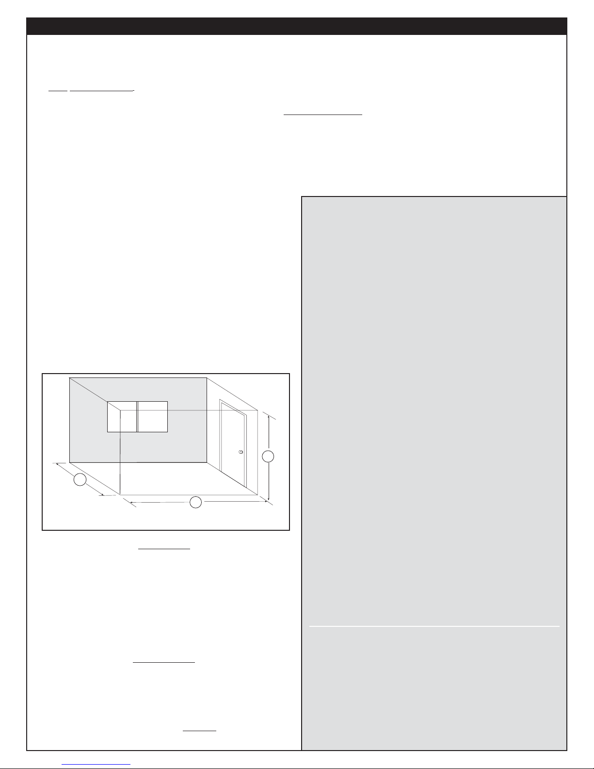
H
W
L
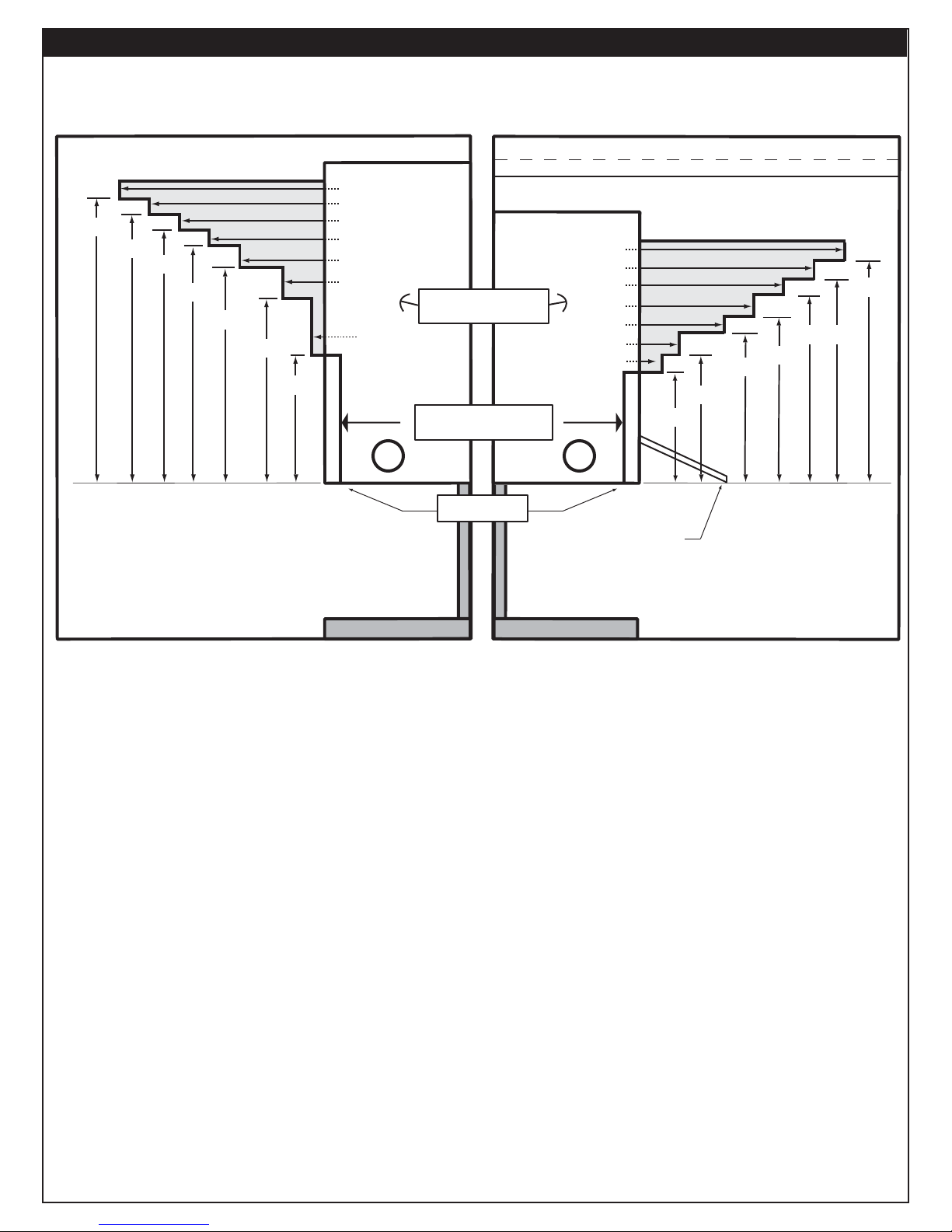
Your vent-free gas burner system SHALL NOT BE INSTALLED IN A CONFINED SPACE or unusually tight
construction unless provisions are made for adequate combustion and ventilation air.
• The National Fuel Gas Code, ANSI Z223.1/NFPA 54 defi nes a confi ned space as a space whose volume is
less than 50 cu. ft. per 1,000 BTU per hour (4.8 meters 3 per kw) of the aggregate input rating of all appliances
installed in that space.
• An unconfi ned space is a space where volume is at least 50 cu. ft. per 1,000 BTU per hour (4.8 meters 3 per
kw) of the aggregate input rating of all appliances installed in that space.
• Rooms communicating directly with the space in which the appliances are installed, through openings not
furnished with doors, are considered a part of the unconfi ned space.
WARNING: Do not install the unvented burner system
where the room is considered a confi ned
space (see Fig. 5-1).
To determine if the area where this burner system
is to be installed fi ts the defi nition of an unconfi ned
space, multiply the length of the room by the width of
the room by the height of the room, then multiply by
20. The result is the maximum BTU allowed.
(Length x Width x Height x 20 = Maximum BTUs allowed)
Example: To install a Peterson Real-Fyre® vent-free
gas burner system with 36,000 BTU, maximum,
in a space with no other gas-burning appliances,
the space MUST be 1,800 cu. ft. or larger.
Assuming an 8' ceiling, fl oor dimensions must be a
minimum of 225 sq. ft.,
i.e.; 18'x12.5'=225 sq ft (see Fig. 5-1).
5-1
Fig.
IT MAY BE NECESSARY TO OPEN A WINDOW
SLIGHTLY (1"- 2") OR OTHERWISE INCREASE
VENTILATION. CONDITIONS REQUIRING THIS
INCLUDE, BUT ARE NOT LIMITED TO:
1. Installation in a CONFINED SPACE.
2. Installation in a HOME OF UNUSUALLY TIGHT
CONSTRUCTION**.
3. Installation at HIGH ALTITUDES.
4. Certain MEDICAL OR PHYSICAL
CONDITIONS OF THE HOMEOWNER that
may be adversely impacted by combustion
products created by burning natural or
propane gas.
Installation in a tightly constructed home and/
or installation at high altitudes may cause your
vent-free burner system to produce excessive heat
or excessive moisture. The oxygen depletion sensor
may shut down the burner system. These conditions
may be corrected by opening a window or otherwise
increasing the number of air changes in the home.
L x W x H x 20 = Maximum BTU allowed
WARNING
If the area in which the heater may be operated is
smaller than that defi ned as an unconfi ned space
or if the building is of unusually tight construction,
provide adequate combustion and ventilation air by
one of the methods described in the National Fuel
Gas Code, ANSI Z223.1/NFPA 54, Air for Combustion
and Ventilation, or applicable local codes.
REMEMBER
L x W x H x 20 = MAXIMUM BTUs ALLOWED
If the space is smaller than the above formula
allows, and/or smaller than the examples and
diagrams on this page specify, DO NOT install
the vent-free burner system unless provisions for
additional combustion and ventilation air are made.
Unusually tight construction is defi ned as construction where:
**
a. Walls and ceilings exposed to the outside atmosphere have a
continuous water vapor retarder with a rating of 1 perm (6x10
kg per pa-sec-m2), or less with openings gasketed or sealed;
b. Weather stripping has been added on openable windows and
doors, and
c. Caulking or sealants are applied to areas such as joints
around window and door frames, between sole plates and fl oors,
between wall-ceiling joints, between wall panels, at penetrations
for plumbing, electrical, and gas lines, and at other openings.
-11
The Peterson Real-Fyre® vent-free burner system
has been certifi ed to function safely and reliably with
emission by-products well within accepted safety and
health standards. Your specifi c medical or physical
condition may render you more sensitive to products
created by burning natural or propane gas. If this is
the case, you should open a window or otherwise
increase ventilation.
5
MINIMUM CLEARANCES TO COMBUSTIBLES
If the vent-free gas log set is installed in a factory
built fi replace, follow the manufacturer’s guidelines for
minimum clearances to combustibles.
In the absence of such guidelines, follow the
instructions below:
Clearances to Combustible Construction:
Sidewalls:
16" from side of fi replace opening (Fig.
6-1).
Ceiling: 42" from top of fi replace opening (Fig. 6-1).
Flooring: See IN FRONT OF FIREPLACE section below.
Mantel: See ABOVE THE FIREPLACE section below &
Fig. 6-1. Also see Fig. x-1, & x-2 on following page).
Note: Clearances to combustible construction
are those distances required to ensure that
fi replace mantels, facings, walls, ceilings, and
fl oorings will not catch fi re.
In most cases, these clearances should also be
adequate to prevent any discoloration or warping
due to heat. However, every gas log installation
presents a different and unique set of circumstances
involving many variables beyond the control of the
gas log manufacturer. These include paint or fi nish
composition, previous exposure to heat, methods and
quality of construction, air fl ow patterns, glass doors,
fans or blowers, etc.
Because of these variables, we cannot guarantee that
heat warping or discoloration will never occur. The
potential for heat warping or discoloration may exist
no matter what item(s) you are burning in the fi replace,
including wood.
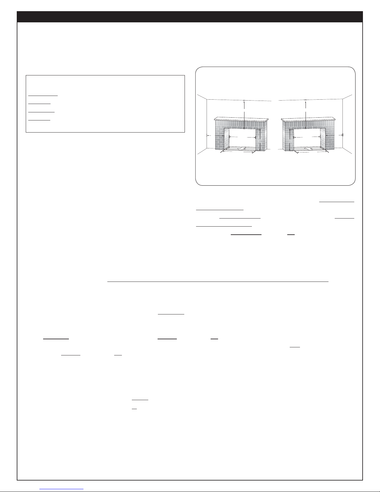
Minimum clearances to
side walls and ceiling
Fig. 6-1
Height
min. 42"
opening
Back
Front
Front
Back
opening width
min
6"
min. 42"
min
6"
Rear
opening
Height
Front
Depth Depth
Front
opening width
Front
Side wall: 16" from side of fi replace opening.
Ceiling: 42" from top of fi replace opening.
The dimensions in Fig. 6-1 are MINIMUM
CLEARANCES to maintain when you install this gas
log set. BOTH SIDES of the fi replace opening MUST
BE AT LEAST 16" from any combustible sidewalls.
The ceiling MUST BE at least 42" from the top of the
fi replace opening.
IN FRONT OF THE FIREPLACE:
Be certain that combustible fl ooring material (i.e.: carpet, tile, etc.) is not too close to the vent-free gas log set.
If the vent-free gas log set is at fl oor level or less than 6" above the fl oor, there MUST be at least 12" (1 foot)
of noncombustible material between the front of the fi replace and any combustible fl ooring.
ABOVE THE FIREPLACE:
To install the vent-free gas log set, there must ALWAYS be noncombustible or heat resistant material immediately
above the fi replace opening. Heat resistant materials (i.e., marble or slate) must be at least 5/8" thick. Sheet
metal should not be installed onto combustible materials.
If you DO NOT install a fi replace hood, there MUST be at least 12" of noncombustible or heat resistant material
immediately above the fi replace opening (see A in Fig. x-1 on the following page). If you DO install a fi replace
hood, there MUST be at least 10" of noncombustible or heat resistant material immediately above the fi replace
opening (see B in Fig. x-2 on the following page). If there is a wooden mantel, shelf, or other combustible
projection above the fi replace, follow the information in the Figures on the next page.
EXAMPLE: If the fi replace has a combustible projection (mantel or shelf) 20" above the top of the fi rebox,
the maximum horizontal projection out from the face of the fi replace will be:
1. If a fi replace hood is not installed - 2.5" (see Fig. x-1 on the following page).
2. If a fi replace hood is installed ------ 10" (see Fig. x-2 on the following page).
A fi replace hood defl ects heat away from the fi replace face and mantel, reducing the potential for heat related
warping or discoloration. The use of a fi replace hood is highly recommended.
IF YOU CANNOT MEET THESE MINIMUM CLEARANCES, YOU MUST OPERATE THE
VENT-FREE GAS LOG SET WITH THE CHIMNEY FLUE DAMPER OPEN.
6
MINIMUM CLEARANCES TO COMBUSTIBLES (Cont.)
IF YOU CANNOT MEET THESE MINIMUM CLEARANCES, YOU MUST OPERATE THE
VENT-FREE GAS LOG SET WITH THE CHIMNEY FLUE DAMPER OPEN.
Mantel clearance without hood
34"
32"
30"
28"
25"
20"
12"
Any combustible material
(mantel) must be within the
shaded area as shown above
Fig. 7-1 Fig. 7-2
14"
12"
10"
8"
6"
2.5"
.75"
Firebox
* Standard Fireplace Hood with minimum 4" horizontal projection
Horizontal projection
from face of fireplace
Fire resistant material
Top of firebox
Firebox
Mantel clearance with hood *
14"
12"
10"
8"
6"
2.5"
1.5"
12"
10"
15"
17"
BA
Fireplace hood with minimum
4" horizontal projection
20"
24"
22"
7
PRE-INSTALLATION AND FIREPLACE PREPARATION SAFETY
CAUTION: Installation and repair must be done by a qualifi ed professional installer.
Installer: Carefully read these instructions before installing this gas burner system. Be sure you understand
all safety precautions and warnings contained in this manual.
PRE-INSTALLATION AND FIREPLACE PREPARATION SAFETY GUIDELINES
A. This appliance is only for use with the type of gas indicated on the rating plate. This appliance is NOT
CONVERTIBLE for use with other gasses.
B. CAUTION: If not installed, serviced, and used correctly per these instructions, this product can cause
serious personal injury, property damage, or loss of life.
C. WARNING: Before installing in a solid-fuel-burning fi replace, the chimney fl ue, damper, and fi rebox must
be thoroughly CLEANED of soot, creosote, ashes, and loose paint by a qualifi ed chimney cleaner. Some
fi replaces (especially older ones) may need repair prior to installing this appliance.
D. CHECK GAS TYPE (natural or propane): The gas supply must be the same as stated on your burner system
rating plate. If gas supply is different, DO NOT INSTALL. Contact your dealer for immediate assistance.
E. Any outside air ducts and/or ash dumps located on the fl oor or walls of the fi replace must be permanently
sealed shut before the installation. Use a heat-resistant sealant. Do not seal the chimney fl ue damper.
F. INSUFFICIENT GAS PRESSURE WILL KEEP THE ODS (OXYGEN DEPLETION SENSOR) PILOT
FROM OPERATING PROPERLY. DO NOT USE IF GAS PRESSURE IS LOWER THAN THE MINIMUM
REQUIREMENT.
G. The
H. The gas piping system must be sized to provide minimum inlet pressure at the maximum fl ow rate (BTU/
I. The minimum clearance from the fi replace opening to combustible materials on side walls and ceiling must
J. At least 10"-12" of noncombustible or heat-resistant material is required above the fi replace. A fi replace
K. Be certain that combustible fl ooring material (i.e., carpet, tile, etc.) is not too close to this gas appliance. If
L. Input ratings shown in BTU per hour are for elevations up to 2,000 ft. For elevations above 2,000 ft., refer to
M. This gas appliance and its main gas valve must be disconnected from the gas-supply piping system during
N. This gas appliance must be isolated from the gas-supply piping system by closing the equipment shutoff
minimum inlet gas-supply pressure for purposes of input adjustment is 5" water column (w.c.) on natural
gas and 11" w.c. on propane gas. Insuffi cient gas pressure will affect proper operation of the ODS pilot. Do
not install this gas appliance if minimum pressure is not available. The maximum inlet gas-supply pressure
is 10.5" w.c. on natural gas and 13" w.c. on propane gas. The propane source must be regulated. (Do not
connect this appliance directly to an unregulated propane gas tank - this can cause an explosion.)
hr). Undue pressure loss will occur if the pipe is too small, or the run is too long.
be maintained as outlined in MINIMUM CLEARANCE TO COMBUSTIBLES - WALLS AND CEILING.
hood will be required to act as a heat defl ector in protecting combustible fi replace surrounds (facing and/or
mantel) if certain minimum clearances cannot be met.
this appliance is at fl oor level or less than 6" above the fl oor, there must be at least 12" of noncombustible
material between the base of the fi replace and any combustible fl ooring.
the National Fuel Gas Code or contact the Robert H. Peterson Company before installing this product.
any pressure testing of that system at test pressures in excess of 1/2 psig.
valve connected to the gas-supply line during any pressure testing of the gas-supply piping system at test
pressures equal to or less than 1/2 psig.
O. Do not use this appliance if any part has been underwater. Immediately call a qualifi ed professional service
technician to inspect the appliance and to replace any part of the control system and any gas control that
has been underwater.
THIS APPLIANCE IS EQUIPPED FOR EITHER NATURAL OR PROPANE GAS.
FIELD CONVERSION IS NOT PERMITTED.
WARNING
8

INSTALLATION SAFETY INFORMATION
INSTALLATION SAFETY GUIDELINES
A. Carefully inspect the burner and cartons for shipping damage. If any parts are missing/damaged,
call your dealer. Do not attempt to install the appliance unless all parts are in good condition.
B. Correct installation of the glass or the ceramic refractory log set and proper placement and
installation of the burner assembly, including ember placement and Lava Granule placement,
are imperative to safe operation of your set. Problems WILL occur if all items are not properly
installed. Reference the INSTALLATION section, LOG PLACEMENT.
C. When installing in a wood-burning fi replace, center the appliance in the fi replace while making
certain that no part of the assembly protrudes (forward) beyond the face of the fi replace.
DO NOT PUSH THE UNIT ALL THE WAY TO THE BACK.
D. If you use Lava Granules, or glass or gems, for decorative use, do not allow these accessories
into or onto any part of the burner or on the logs. Lava Granules, or glass or gems used to
accessorize the vent-free burner, should only be placed on the fl oor of the fi replace, in front of
and to the sides of the burner, but away from the controls.
E. DO NOT PLACE logs or other accessories, such as wood chips, pine cones, or vermiculite, on
this appliance. These items will cause improper burning, sooting, and/or high levels of carbon
monoxide. Additional logs and/or accessories may be placed around the burner system, as long
as they do not interfere with the burning of your gas appliance.
F. Due to high temperatures, this appliance should be located out of traffi c and away from
furniture/draperies.
G. A fi replace screen must be in place when this gas appliance is in operation. Unless other
provisions for combustion air are provided, the screen shall have an opening(s) for introduction
of combustion air.
H. Connecting directly to an unregulated propane tank can cause an explosion.
I. Special care is required if you are installing the unit into a SUNKEN FIREPLACE. You must raise
the fi replace fl oor to allow access to gas controls. This will ensure adequate airfl ow and guard
against sooting. Raise the fi replace fl oor using noncombustible materials.
J. A vent-free room heater having an input rating of more than 10,000 BTU per hour shall not be
installed in a bedroom (ANSI Z21.11.2).
If local codes allow, you may install a G8-xxR burner, having a rating of 9,500 BTU, in a bedroom.
An unvented room heater having an input rating of more than 6,000 BTU per hour shall not be
installed in a bathroom (ANSI Z21.11.2).
9
 Loading...