

RealFlame PYROTECH Installation & Operating Manual
PYROTECH
®
INSTALLATION & OPERATING MANUAL
2012
The Pyrotech Space Heater range are approved to be installed into a
masonry fireplace, as a zero clearance firebox enclosed by a timber
frame and plastered or as a free standing unit. The Pyrotech Range is
approved to operate on Natural Gas and Propane (LPG) gases only.
Approval Number: GMK10092
VERSION 12

2
WARRANTY INFORMATION
The benefits provided to you under the following warranty are in addition to any other rights and remedies available to
you under the law.
1. Warranty
If:
(a) during the first 10 years from the date of purchase (Firebox Warranty Period), there is a defect in the firebox of the
Real Flame Gas Burner; or
(b) during the first 12 months from the date of purchase (Parts Warranty Period), there is a defect in the gas valves or
other parts of the Real Flame Gas Burner,
due to improper workmanship or material, Real Flame will replace or repair the Real Flame Gas Burner without
charge. Any replacement product is warranted only for the time remaining on the original Firebox Warranty
Period or the Parts Warranty Period as relevant.
2. Registration
You must register to receive the benefit of this warranty by completing the warranty registration on our website
(www.realflame.com.au) or completing and mailing the attached registration card within 30 days of purchase of
your Real Flame Gas Burner (or, if the Real Flame Gas Burner is fitted to a new home, within 30 days of the date
of settlement of purchase of such new home).
3. Exclusions
Real Flame is not obliged to replace or repair the Real Flame Gas Burner under clause 1 if:
(a) it has been improperly stored, installed, connected, used, operated or repaired, or damaged, abused, tampered
with, altered (without our written approval), or not maintained in strict accordance with our installation and
operating instructions; or
(b) it has been installed in an outdoor setting.
4. Limit of Liability
The warranty provided under this warranty is limited to replacement or repair of the Real Flame Gas Burner only,
at our option. To the extent permitted by law, Real Flame excludes liability for consequential loss or any other loss
or damage caused to property or persons arising from any cause whatsoever, and damage arising from normal
wear and tear.
5. Claiming under the Warranty
In order to claim under this warranty you must, within the Firebox Warranty Period or the Parts Warranty Period
(as relevant), contact Real Flame, providing the original proof of purchase and the details below:
Supplier Name___________________________________________________________________________
Date Of Purchase / settlement of property if new home _________________
Model / Serial Number_______________________
This warranty does not cover the cost of claiming under the warranty or transporting the Real Flame Gas Burner to and
from the supplier.
Our goods come with guarantees that cannot be excluded under the Australian Consumer Law. You are entitled to a
replacement or refund for a major failure and for compensation for any other reasonably foreseeable loss or damage.
You are also entitled to have the goods repaired or replaced if the goods fail to be of acceptable quality and the failure
does not amount to a major failure.
If you would like to speak to someone about your Real Flame Gas Burner or claiming under this warranty, please
contact the Real Flame Service Warranty Desk on 03 8706 2000.
Real Flame Pty Ltd ACN 006 311 155
Head Office: 1340 Ferntree Gully Road, Scoresby 3179
Telephone: 03 8706 2000 Facsimile: 03 8706 2001
INSTALLATION NOTICE
The installation of this appliance is only to be carried out by an authorised person in accordance
with the Manufacturer’s Instructions, local gas fitting regulations, AS5601-2004 installation code for
gas burning appliances and any other relevant statutory regulations.
In all cases the installation of this appliance shall meet the requirements as set out in AS5601-2004.
WARNING
The Pyrotech range of fires have a primary safety glass fitted in front of the glass door. This safety glass is
fitted to this appliance to reduce the risk of injury from burns and at no time should this glass be
permanently removed.
For protection of young children or the infirm, a secondary guard is required.
NOTE: A slight smell may be apparent for the first few hours of use. This is due to the heat resistant
paint curing. It is recommended to open windows in the room for the first lighting of the fire. In some
instances a slight discolouration may occur inside the firebox. This is a normal condition and is not
covered by warranty.
This heater is designed to have a luminous flame and may exhibit a slight carbon deposit.
IMPORTANT SAFETY NOTICE
DO NOT PLACE ARTICLES ON OR AGAINST THIS APPLIANCE.
DO NOT USE OR STORE FLAMMABLE MATERIAL NEAR THE APPLIANCE.
DO NOT SPRAY AEROSOLS IN THE VICINITY OF THIS APPLIANCE WHILST IT IS IN OPERATION.
DO NOT OPERATE WITH GLASS PANEL REMOVED FROM THIS APPLIANCE.
VENTILATION REQUIREMENTS
ADDITIONAL VENTILATION IS REQUIRED ONLY IF THE UNIT IS INSTALLED IN A ROOM OF LESS
THAN 10 CUBIC METRES IN SIZE - REFER AS/NZS 5601 CLAUSE 5,4,3,1.
3
SERVICING
It is recommended you service your gas fire every 2 years as a minimum.

CONTENTS
Contents...................................................................................................................4
Data Plate.................................................................................................................5
Inbuilt Model Dimensions/Installation Procedure....................................................6
Zero Clearance Model Timber Frame Installation Procedure .................................9
Zero Clearance Model ..........................................................................................10
Zero Clearance Model Assembly...........................................................................11
Zero Clearance Model Dimensions/Installation Procedure...................................12
Freestanding Model Dimensions...........................................................................13
Freestanding Model Installation Procedure/Clearances .......................................14
Flue Requirements.................................................................................................15
Dimensions ............................................................................................................16
Lighting pilot and main burner (Standard models only) .......................................18
Tests to be carried out by installer.........................................................................19
Servicing and Maintenance ...................................................................................20
Parts Location/Parts Kit (Standard models only)...................................................25
Gas Control Assembly/Valve Description..............................................................26
Parts List (Deluxe models only) .............................................................................27
Gas Control Assembly ...........................................................................................28
Troubleshooting for Pyrotech Standard ................................................................29
Troubleshooting for Pyrotech Deluxe ....................................................................30
Flue Termination Regulations ................................................................................31
Optional Marble Surround Installation Procedure.................................................32
Optional Mantelpiece Installation Procedure/Dimensions ....................................33
Electrical Diagram (Standard models only)...........................................................34
Electrical Diagram (Deluxe models only) ..............................................................35
Real Flame Contact Information ............................................................................36
4
MODEL: PYROTECH STANDARD 2012 WEIGHT: 56 kg
INJ/SIZE MJ/H P.T.P.TYPE
2 x 1.65mm 28 1.00 kpa HIGH
2 x 1.65mm 21.5 0.63 kpa LOW
2 x 1.05mm 28 2.55 kpa HIGH
2 x 1.05mm 23.5 1.74 kpa LOW
NG PRIMARY
APPROVAL NUMBER SERIAL NUMBER DATE OF MANUFACTURE
GMK10092
NG SECONDARY
LPG PRIMARY
LPG SECONDARY
MODEL: PYROTECH DELUXE 2012 WEIGHT: 56 kg
INJ/SIZE MJ/H P.T.P.TYPE
2 x 1.65mm 28 1.00 kpa HIGH
2 x 1.65mm 18 0.45 kpa LOW
2 x 1.05mm 28 2.50 kpa HIGH
2 x 1.05mm 18 0.95 kpa LOW
NG PRIMARY
APPROVAL NUMBER SERIAL NUMBER DATE OF MANUFACTURE
GMK10092
NG SECONDARY
LPG PRIMARY
LPG SECONDARY
DATA PLATE
5
PYROTECH INBUILT MODEL
• Unit installed into an existing “working” fireplace requires an AGA approved 150mm gas cowl.
If the chimney does not draw properly, a 900mm length of flexi flue (supplied with unit) should
be fixed to the flue spigot on top of the heater. The flexi flue should be fixed in the vertical
position in a manner that does not allow the flue to fall or come away from the spigot.
• If the fireplace is not a working fireplace, then an approved 100mm flue system with 100mm
AGA approved gas cowl should be used. (Optional extra)
• If the flue is exposed or enclosed with combustible materials, an approved 100/150mm twin
skin flue is required. (Optional extra)
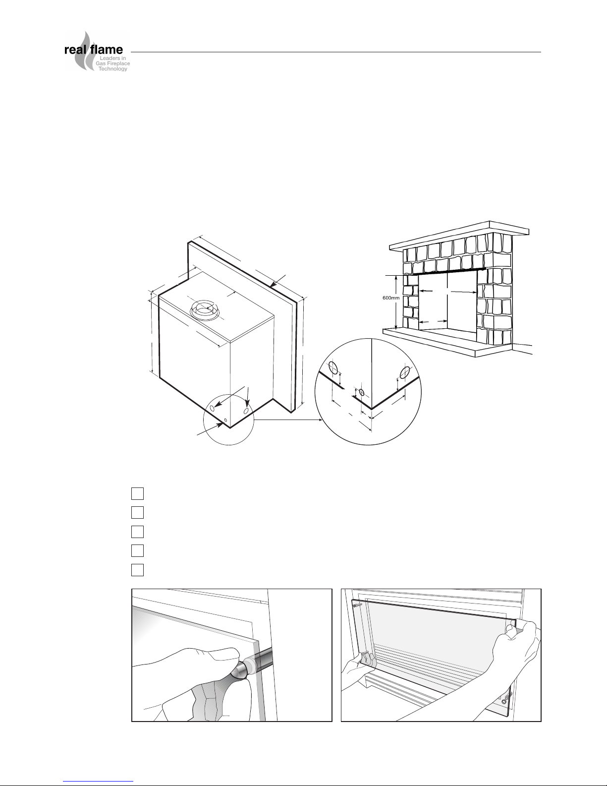
Pyrotech Inbuilt Installation Procedure
Check chimney for correct venting of fumes
Position unit centrally.
Connect to gas supply using 15mm copper union.
Connect to power supply.
Remove glass and assemble log or pebble set as shown (Figures 1 - 12).
TICK BOXES
Figure (1) Remove decorative fasteners from
four corners of shield glass panel.
Figure (2) Remove shield glass panel.
572mm
Gas Pipe
(Alternatives)
Electrical Cord
360mm
865mm
635mm
280mm
600mm
170mm
45mm
30mm
40mm
45mm
240mm
Trim
680mm
370mm
6

Pyrotech Inbuilt Installation Procedure (continued)
Figure (3) Remove nylon grommets and put
aside carefully.
Figure (4) Remove three spacer bolts, and
loosen bolt in bottom right corner.
Figure (5) Support front glass as shown, and
remove fourth spacer bolt. Remove
front glass.
Figure (6) Remove box containing logset, and
unpack. Place the large log at the rear
of the burner just in front of the 2
square tabs on the log support panel.
Re-installation of glass panels is reverse of
above. N.B: ensure that the roped edge of
the glass is fitted to the top.
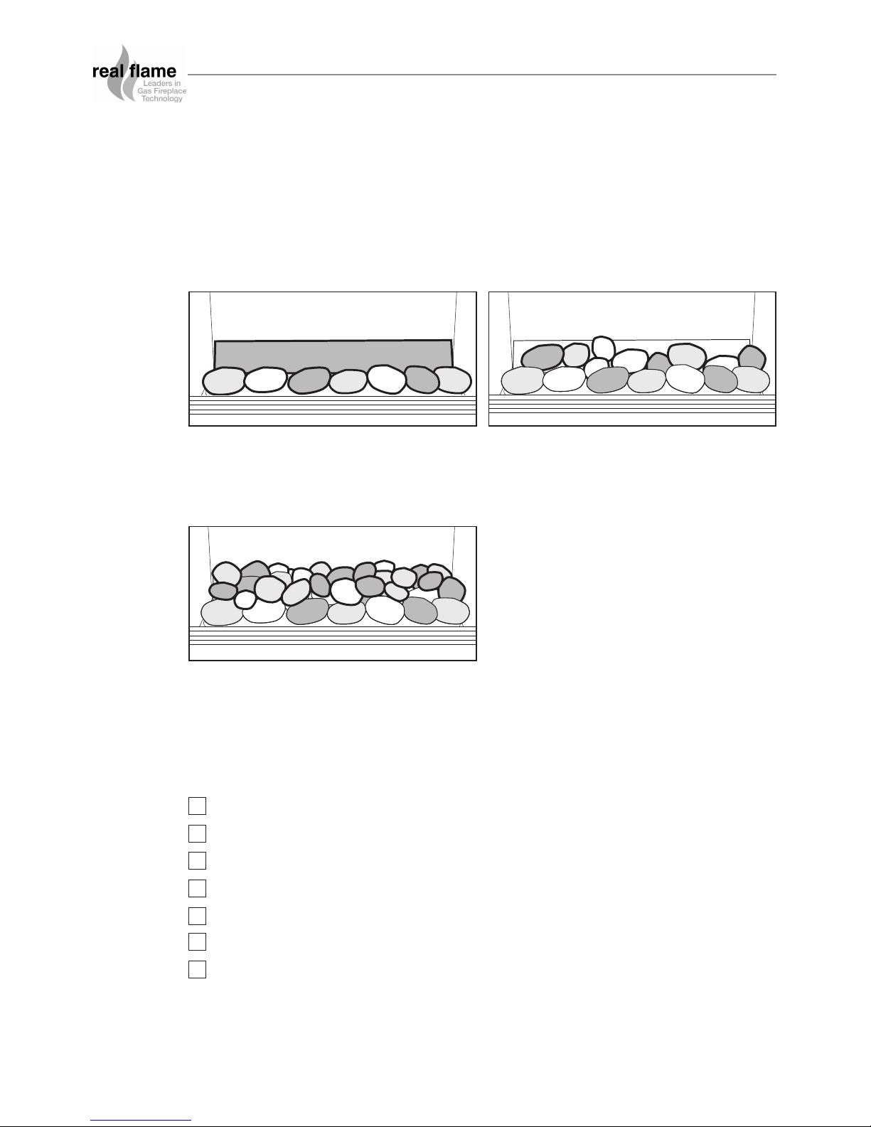
Figure (7) Place the 14 large coals and 8 small coals
on top of the white ceramic blanket.
Ensure front row of coals are placed
10 - 12mm away from the front grille.
Figure (9) Place the 2 straight logs as shown
Figure (8) Place the 2 ‘Y’ shaped logs as
shown, the larger on the left.
Position the ‘Y’ end of the logs
towards the front of the heater.
PYROTECH INBUILT MODEL
NOTE: Keep coals or pebbles clear
of burner rail.
7
The Pyrotech Space Heater (Natural Gas Only) is approved for use with Pebbles.
To install the Pebbles follow the installation instructions as per Figures 1 to 5 above, and then
proceed as follows (Figures 10 to 12).
Note: If a coals only configuration is being used, use the same set up as pebbles.
Pyrotech Inbuilt Installation Procedure (continued)
Figure (10) Install the metal angle at the rear of
the fireplace and place one row of
pebbles behind the burner rail.
Figure (11) Place pebbles between the first row
and the angled tray.
Figure (12) Place remaining pebbles up the
angle of the rear tray so as the tray
is hidden.
Replace the glass front to its original position.
Fit the trim to the front of the heater.
Light the unit following the procedure on page 17.
Install the 150mm AGA approved gas cowl where using the chimney to vent the fumes.
Test the unit for safe operation and show customer correct operating procedures.
Test for spillage.
Perform pressure test.
TICK BOXES
PYROTECH INBUILT MODEL
Note: Keep pebbles clear of burner rail.
8
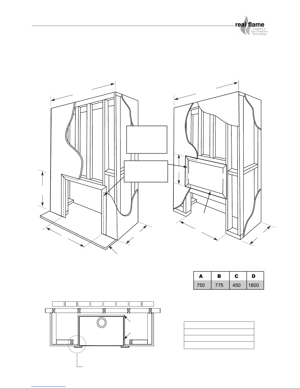
Pyrotech Zero Clearance Timber Frame Installation
Floor 0 mm
Sides 50 mm
Top 100 mm
Flue Outer 50 mm
CLEARANCES FROM
COMBUSTIBLES
NOTE: Note: If fire is to be installed off the floor with 4
sided trim, use same A, B, C and D dimensions as shown
with frame work included below fire to required height.
Plasterboard to run beyond stud as shown,
and to go behind fixing flange on unit.
Min 50mm
clearance
NOTE
PYROTECH ZERO CLEARANCE MODEL
IMPORTANT
Install unit and
fluing before
plasterboard.
A
A
B
B
C
C
D
(Recommended only)
From hearth
Approx 20mm for
hearth if required.
D
(Recommended only)
HEATER
TRIM
Plaster to run
beyond stud and
behind trim
9
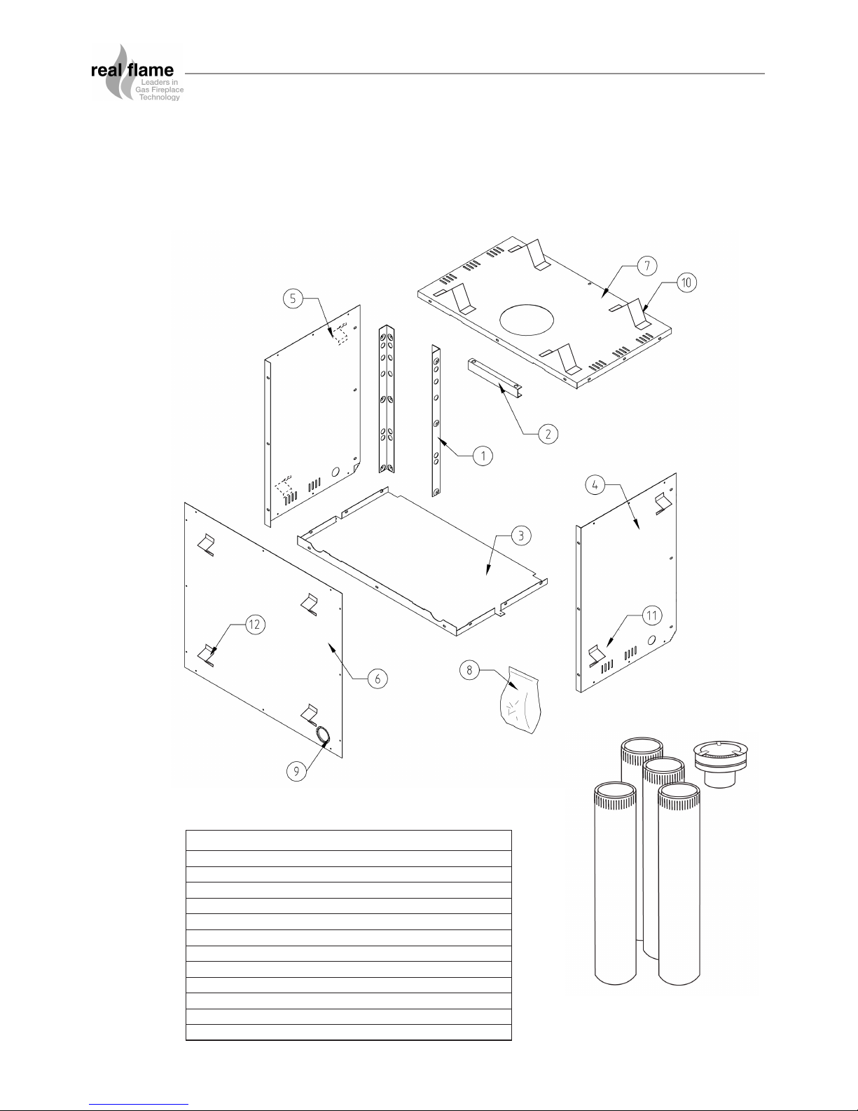
PYROTECH ZERO CLEARANCE MODEL
1. Position the Pyrotech firebox in the selected installation position in the room.
2. You will require the Zero Clearance Kit to suit, which is to be fitted to the main fire box as
shown on page 11.
No. Description Qty
1 Panel – Side Strip 2
2 Panel – Top Strip 1
3 Panel – Base 1
4 Panel – Side L/H 1
5 Panel – Side R/H 1
6 Panel – Rear (with cord protector around large hole) 1
7 Panel – Top 1
8 Plastic Bag (Containing screws 35 off) 1
9 Cord Protector in place (154mm long) 1
10 100mm Stand Off 4
11. 50mm Stand Off (2 x RH + 2 x LH) 4
12. 25mm Stand Off 4
ZERO CLEARANCE KIT COMPONENTS
FLUE KIT
10
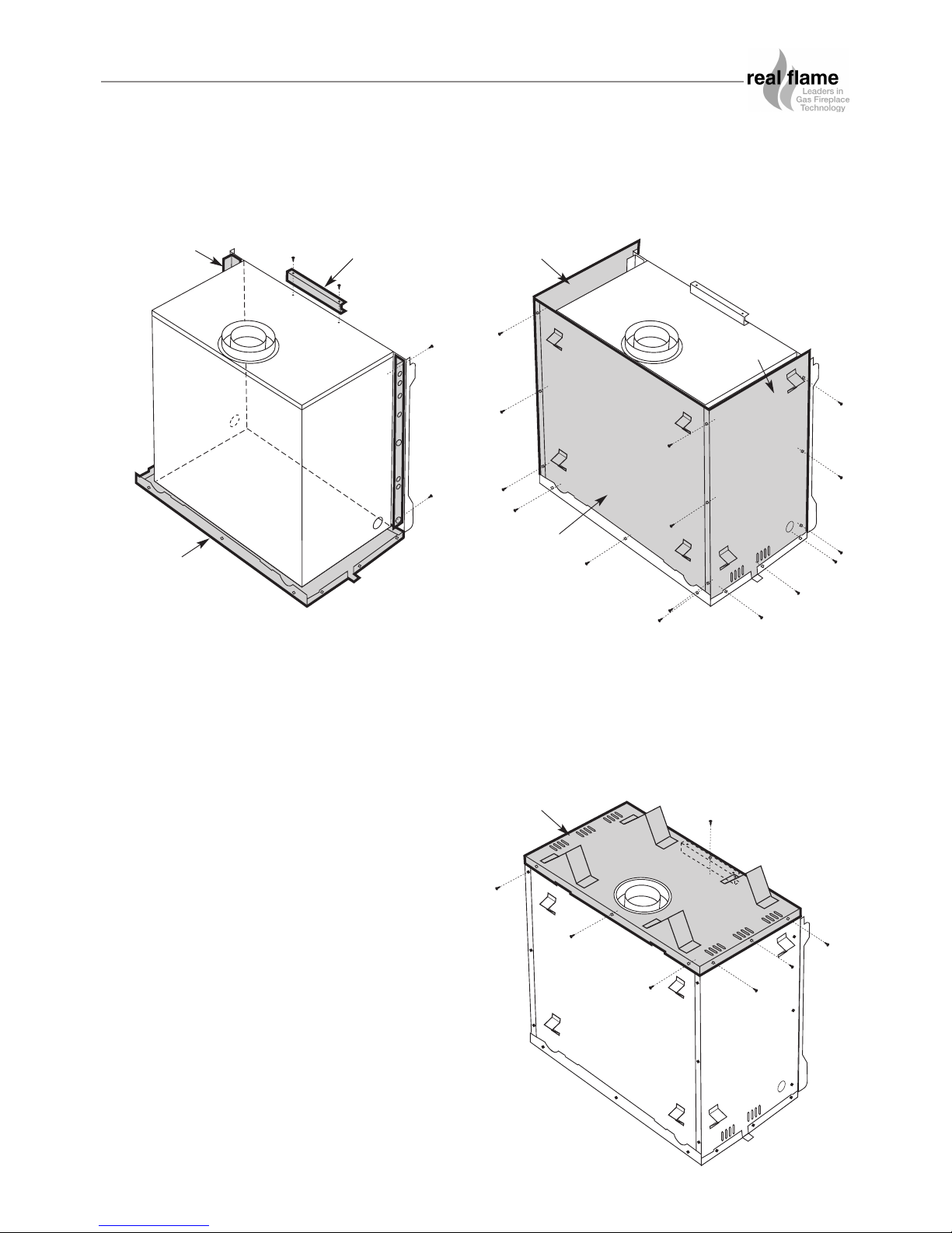
1. Secure side strips (Item 1) to side brackets on fire
box using screws (2 off per side strip).
Remove 2 top screws in fire box and place top
strip (Item 2) into position and secure using 2
screws.
Place base panel (Item 3) under fire box.
2. Place LH side panel (Item 4) in behind lip of base
panel. Secure side panel to side strip and base
panel in 6 places.
Repeat for RH side panel (Item 5). Place rear
panel (Item 6) in behind folds on side panels and
base panel. Secure rear panel using screws
9 off.
3. Place top panel (Item 7) onto assembly. Ensure
all other panels sit behind folds on top panel.
Secure top panel 9 places around edge and 1
screw on the top in the centre passing through
hole in top strip as shown.
PYROTECH ZERO CLEARANCE MODEL
Fit Zero Clearance Kit to unit as shown below:
ITEM 2
ITEM 5
ITEM 6
ITEM 4
ITEM 1
ITEM 3
ITEM 7
11
 Loading...