

Real Flame Magiglo Series, Magiglo 320, Magiglo 360, Magiglo 750, Magiglo 1000 Installation & Operating Manual
...
®
MAGIGLO
INSTALLATION & OPERATING MANUAL
The Magiglo series of decorative fires are suitable to be installed into a
masonry or approved prefabricated fireplace and are designed to operate
with Natural and Propane gases only. Approval Number GMK10098.
VERSION 20
SERIES
WARRANTY INFORMATION
The benefits provided to you under the following warranty are in addition to any other rights and remedies available to
you under the law.
1. Warranty
If:
(a) during the first 15 years from the date of purchase (Firebox Warranty Period), there is a defect in the firebox of
the Real Flame Gas Burner; or
(b) during the first 2 years from the date of purchase (Parts Warranty Period), there is a defect in the gas valves or
other parts of the Real Flame Gas Burner,
due to improper workmanship or material, Real Flame will replace or repair the Real Flame Gas Burner without
charge. Any replacement product is warranted only for the time remaining on the original Firebox Warranty
Period or the Parts Warranty Period as relevant.
2. Registration
You must register to receive the benefit of this warranty by completing the warranty registration on our website
(www.realflame.com.au) or completing and mailing the attached registration card within 30 days of purchase of
your Real Flame Gas Burner (or, if the Real Flame Gas Burner is fitted to a new home, within 30 days of the date
of settlement of purchase of such new home).
3. Exclusions
Real Flame is not obliged to replace or repair the Real Flame Gas Burner under clause 1 if:
(a) it has been improperly stored, installed, connected, used, operated or repaired, or damaged, abused, tampered
with, altered (without our written approval), or not maintained in strict accordance with our installation and
operating instructions; or
(b) it has been installed in an outdoor setting.
4. Limit of Liability
The warranty provided under this warranty is limited to replacement or repair of the Real Flame Gas Burner only,
at our option. To the extent permitted by law, Real Flame excludes liability for consequential loss or any other
loss or damage caused to property or persons arising from any cause whatsoever, and damage arising from
normal wear and tear.
5. Claiming under the Warranty
In order to claim under this warranty you must, within the Firebox Warranty Period or the Parts Warranty Period
(as relevant), contact Real Flame, providing the original proof of purchase and the details below:
Supplier Name___________________________________________________________________________
Date Of Purchase / settlement of property if new home _________________
Model / Serial Number_______________________
This warranty does not cover the cost of claiming under the warranty or transporting the Real Flame Gas Burner to and
from the supplier.
Our goods come with guarantees that cannot be excluded under the Australian Consumer Law. You are entitled to a
replacement or refund for a major failure and for compensation for any other reasonably foreseeable loss or damage.
You are also entitled to have the goods repaired or replaced if the goods fail to be of acceptable quality and the failure
does not amount to a major failure.
If you would like to speak to someone about your Real Flame Gas Burner or claiming under this warranty, please
contact the Real Flame Service Warranty Desk on 1300 554 155.
Glen Dimplex Australia Pty Ltd ACN 69 118 275 460
Head Office: 1340 Ferntree Gully Road, Scoresby 3179
Telephone: (03) 8706 2000 Facsimile: (03) 876 2001
2
INSTALLATION NOTICE
The installation of this appliance is only to be carried out by an authorised person in accordance
ith the Manufacturer’s Instructions, local gas fitting regulations, AS/NZS5601.1-2013 installation
w
code for gas burning appliances and any other relevant statutory regulations.
In all cases the installation of this appliance shall meet the requirements as set out in
AS/NZS5601.1-2013
NOTE: A slight smell may be apparent for the first few hours of use. This is due to the heat
resistant paint curing. It is recommended to open windows in the room for the first lighting of the
fire. In some instances a slight discolouration may occur inside the firebox. This is a normal
condition and is not covered by warranty.
IMPORTANT SAFETY NOTICES
DO NOT PLACE ARTICLES ON OR AGAINST THIS APPLIANCE.
DO NOT USE OR STORE FLAMMABLE MATERIAL NEAR THE APPLIANCE.
DO NOT SPRAY AEROSOLS IN THE VICINITY OF THIS APPLIANCE WHILST IT IS IN OPERATION.
CARE MUST BE TAKEN TO ENSURE THAT ANY RETURN AIR REGISTER OR EXHAUST SYSTEM
DOES NOT ADVERSLEY AFFECT THE OPERATION OF THE APPLIANCE OR DRAUGHT OF
CHIMNEY OR FLUE.
DO NOT MODIFY THIS APPLIANCE.
THIS APPLIANCE IS DESIGNED TO OPERATE WITH LUMINOUS FLAMES. THIS MAY EXHIBIT
SLIGHT CARBON DEPOSITS.
VENTILATION REQUIREMENTS
Permanent ventilation of the room where the fire is to be situated is essential while fire is in operation.
The room must have a minimum cross sectional area of 40,000sq mm of effective ventilation.
WARNING
This firebox has a naked flame, care should be taken when it is operating if children or the infirm are in
close proximity. A safety screen is recommended if constant supervision is not possible. It is
recommended that a secondary guard complying with AS-NZS2286 be installed.
The appliance is not intended for use by persons (including children) with reduced physical, sensory or
mental capabilitites, or lack of experience and knowledge, unless they have been given supervision or
instruction concerning use of the appliance by a person responsible for their safety. Children should be
supervised to ensure that they do not play with the appliance.
THIS IS PRIMARILY A DECORATIVE APPLIANCE AND IS NOT CERTIFIED AS A SPACE HEATER.
3

CONTENTS
Contents .................................................................................................................4
Data Plate ...............................................................................................................5
Dimensions .............................................................................................................6
nstallation Instructions .........................................................................................10
I
Lighting Instructions ..............................................................................................11
Commissioning Procedure ...................................................................................13
Typical Type 1 Installation to existing chimney ....................................................14
Type 1 Installation into Victorian/Federation grate ...............................................15
Typical Type 2 Installation of Prefabricated Fire Box into existing chimney ........16
User Instructions...................................................................................................17
Troubleshooting ....................................................................................................17
Conversion details ................................................................................................18
Parts List...............................................................................................................19
Real Flame contact information............................................................................20
4
DATA PLATE (Affixed to the base of the unit for reference to gas pressure & consumption)
BURNER MODEL NATURAL GAS ULPG
INJ. SIZE MJ/Hr TPP (kPa) INJ. SIZE MJ/Hr TPP (kPa)
320 2.40 23 0.80 1.20 20 2.60
60 2.50 26 0.80 1.30 21 2.70
3
400 2.60 28 0.80 1.30 21 2.70
540 2.25 37 0.80 1.10 33 2.60
750 1.85 39 0.75 0.95 34 2.55
1000 2.25 49 0.75
540 Double Burner 2.80 54 0.87 ---
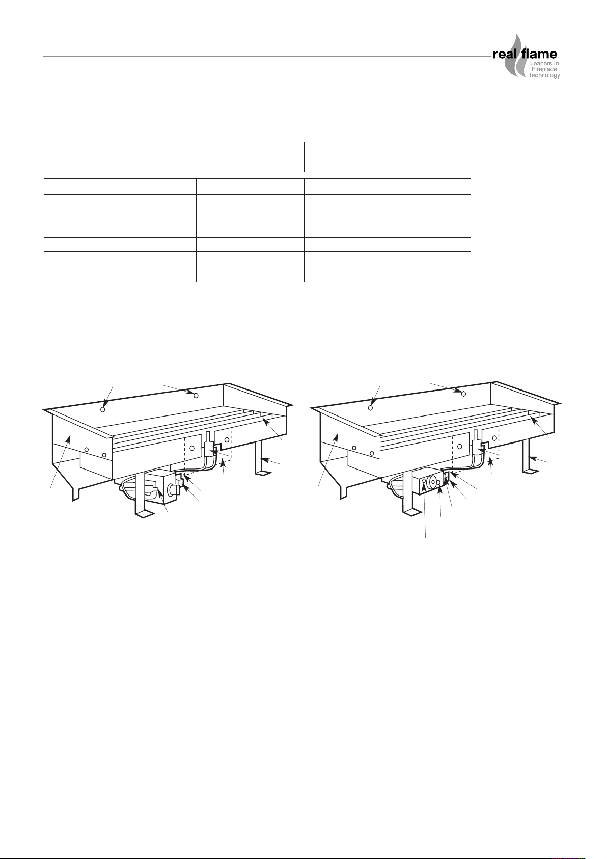
PARTS
Magiglo 320 & 360 Magiglo 400, 540 & 750
ear Log Fixing Hole
ear Log Fixing Hole
R
R
Detachable Skirt
urner Port
B
ilot Cover Plate
P
Gas Connection
Pilot
Assembly
ressure Test
P
Pilot Cover Plate
Gas Connection
egulator Adjustment
R
ilot
P
Assembly
Fixing
Bracket
etachable Skirt
D
Burner Pressure Test Point
Maximum Pressure Setting Screw
Minimum Pressure Setting
Pilot Pressure Adjustment
TO CHECK PRESSURES
1. Fit manometer to test point.
2. Adjust pilot pressure screw (wind screw fully in, then wind out 2 1/2 full turns - for 400, 540 &
750 models only).
3. Adjust maximum burner pressure screw (wind max pressure screw out 2 full turns - for 400,
540 & 750 models only).
4. Ignite burner and set to maximum rate.
5. Adjust regulator pressure until burner pressure is correct.
6. Adjust maximum burner pressure - screw in adjustment screw to data plate setting.
7. Turn valve to low setting. Adjust valve minimum pressure.
8. Complete tests for safety/leakage and connections.
9. Turn burner off.
10. Replace regulator cap.
11. Remove manometer, replace sealing screw and washer and refit valve cover.
urner Port
B
Fixing
Bracket
5
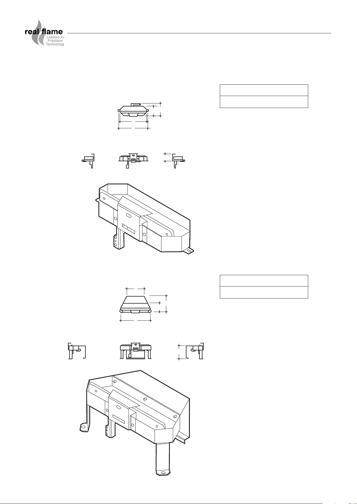
DIMENSIONS
PLAN
RHS
LHS
B
A
C
E
FRONT
D
PLAN
FRONT
RHSLHS
B
A
C
D
E
Magiglo 320 Burner
ABCDE
147 110 341 317 84
Magiglo 360
ABCDE
199 110 210 360 155
6
 Loading...