

Real Flame LANDSCAPE 1000, LANDSCAPE 1600 Installation & Operating Manual
LANDSCAPE
®
BALANCED
FLUE SPACE HEATER
INSTALLATION & OPERATING MANUAL
The Landscape 1000 & 1600 are approved to be installed as a zero
clearance firebox and are designed to operate on Natural Gas and
Propane (LPG) gases ONLY. Approval Number GMK 10056.
VERSION 19
2
WARNING
The “Landscape 1000 & 1600” have a primary safety glass fitted in front of the glass door. This safety glass
is fitted to these appliances to reduce the risk of injury from burns and at no time should this glass be
permanently removed.
For protection of young children or the infirm, a secondary guard is required.
WARRANTY
Provided your Real Flame gas fire is installed in strict accordance with our installation instructions, the
firebox is unconditionally guaranteed for ten years and all other parts for twelve months from date of
purchase.
This unconditional warranty covers parts and labour at our discretion taking into consideration normal wear
and tear and does not cover fires installed in outdoor settings.
INSTALLATION NOTICE
The installation of this appliance is only to be carried out by an authorised person in accordance
with the Manufacturer’s Instructions, local gas fitting regulations, AS5601-2004 installation code
for gas burning appliances and any other relevant statutory regulations.
Do not modify this appliance.
In all cases the installation of this appliance shall meet the requirements as set out in
AS5601-2004.
NOTE: A slight smell may be apparent for the first few hours of use. This is due to the heat resistant
paint curing. It is recommended to open windows in the room for the first lighting of the fire. In some
instances a slight discolouration may occur inside the firebox. This is a normal condition and is not
covered by warranty.
IMPORTANT SAFETY NOTICE
DO NOT PLACE ARTICLES ON OR AGAINST THIS APPLIANCE.
DO NOT USE OR STORE FLAMMABLE MATERIAL NEAR THE APPLIANCE.
DO NOT SPRAY AEROSOLS IN THE VICINITY OF THIS APPLIANCE WHILST IT IS IN OPERATION.
CARE MUST BE TAKEN TO ENSURE THAT ANY RETURN AIR REGISTER OR EXHAUST SYSTEM
DOES NOT ADVERSLEY AFFECT THE OPERATION OF THE APPLIANCE OR DRAUGHT OF
CHIMNEY OR FLUE.
WARNING
The outer glass panel gets extremely hot! Precaution should be taken and young children
supervised at all times when heater is operating.

CONTENTS
Contents ..................................................................................................................3
Data Plate.................................................................................................................4
Zero Clearance introduction ....................................................................................5
Dimensions Landscape 1000 ..................................................................................6
Dimensions Landscape 1600 ..................................................................................7
Terminations .............................................................................................................8
Timber frame installation..........................................................................................9
Vertical & horizontal venting installation................................................................12
Tests to be carried out by installer .........................................................................13
Pebble set up .........................................................................................................13
Servicing and maintenance ...................................................................................14
Parts list ................................................................................................................16
Gas control assembly ............................................................................................17
Flue termination (cowls) regulations .....................................................................18
Remote control operating guide............................................................................19
Electrical diagram ..................................................................................................22
Troubleshooting .....................................................................................................24
Real Flame contact information .............................................................................28
3
4
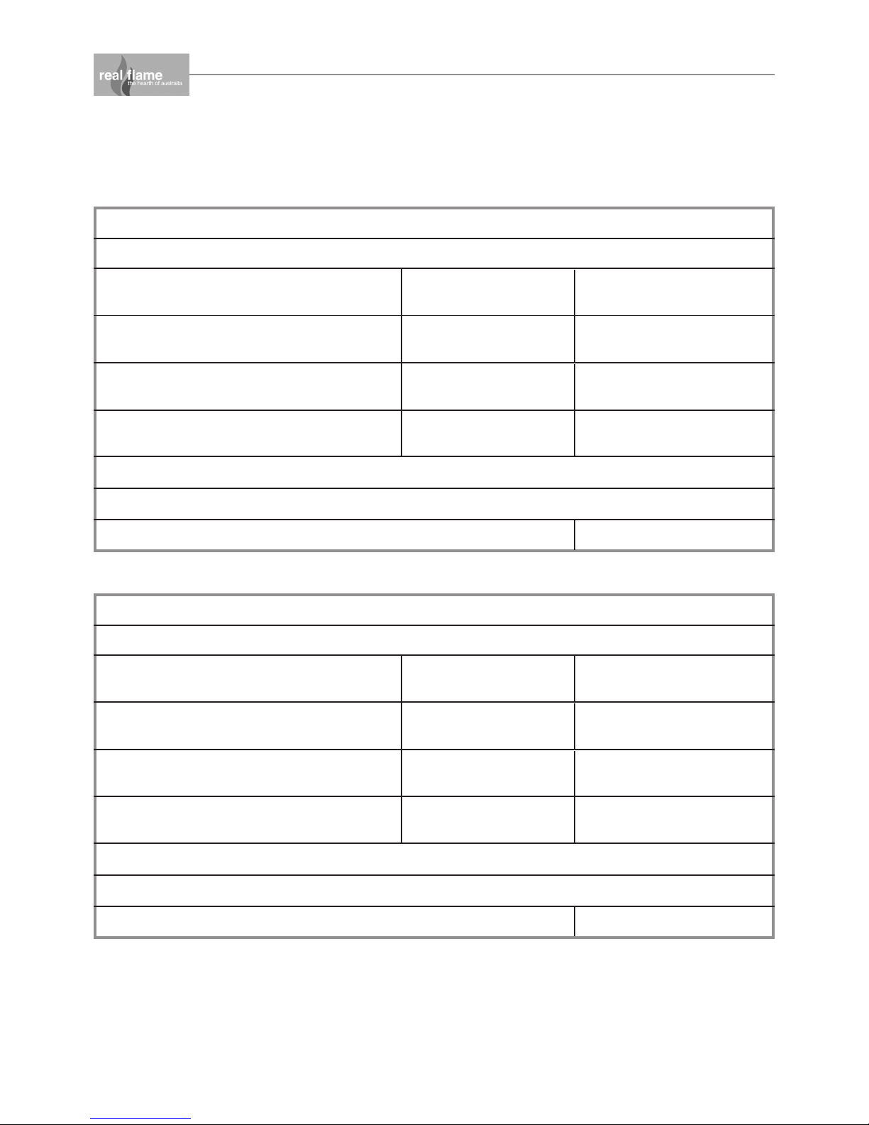
DATA PLATE (Affixed to the base of the unit for reference to gas pressure & consumption)
MODEL LANDSCAPE 1000
GAS TYPE
NATURAL GAS @ 0.8 kPa
TEST PRESSURE POINT (HIGH)
INJECTOR SIZE
3 X 2.3mm
GAS CONSUMPTION
41Mj/h
LPG @ 2.6 kPa
TEST PRESSURE POINT (HIGH)
INJECTOR SIZE
3 X 1.1mm
GAS CONSUMPTION
41Mj/h
NATURAL GAS @ 0.40 kPa
TEST PRESSURE POINT (LOW)
INJECTOR SIZE
3 X 2.3mm
GAS CONSUMPTION
28Mj/h
LPG @ 0.90 kPa
TEST PRESSURE POINT (LOW)
INJECTOR SIZE
3 X 1.1mm
GAS CONSUMPTION
28Mj/h
APPROVAL NO: GMK10056
SERIAL NUMBER:
DATE OF MANUFACTURE
MODEL LANDSCAPE 1600
GAS TYPE
NATURAL GAS @ 1.00 kPa
TEST PRESSURE POINT (HIGH)
INJECTOR SIZE
4 X 2.75mm
GAS CONSUMPTION
51Mj/h
LPG @ 2.6 kPa
TEST PRESSURE POINT (HIGH)
INJECTOR SIZE
4 X 1.0mm
GAS CONSUMPTION
51Mj/h
NATURAL GAS @ 0.40 kPa
TEST PRESSURE POINT (LOW)
INJECTOR SIZE
4 X 2.75mm
GAS CONSUMPTION
31Mj/h
LPG @ 1.50 kPa
TEST PRESSURE POINT (LOW)
INJECTOR SIZE
4 X 1.0mm
GAS CONSUMPTION
38Mj/h
APPROVAL NO: GMK10056
SERIAL NUMBER:
DATE OF MANUFACTURE
WEIGHT 132 KG
WEIGHT 195 KG

LANDSCAPE MODEL
5
INTRODUCTION
The Real Flame “Landscape” is a ribbon burner space heater for use with Natural Gas Aus & NZ
and Propane.
The Real Flame warranty will be voided by, and Real Flame disclaims any responsibility for the
following actions:
• Modification of the space heater and/or components including balanced flue assembly or
glass door.
• Use of any component part not manufactured or approved by Real Flame in combination
with this “Landscape” fireplace system.
• Installation other than as instructed in this manual.
CAUTIONS
• Due to its high operating temperature, the appliance should be located out of traffic and
away from furniture and draperies.
• Children and adults should be alerted to the hazards of the high surface temperature, which
could cause burns or clothing ignition.
• Young children should be carefully supervised when they are in the same room as the
appliance.
• Clothing or other flammable materials must not be placed on or near the appliance.
SELECTING YOUR APPLIANCE LOCATION
Your appliance may be installed in any location that is free of air conditioning ducts, electrical
wiring and plumbing. Safety, as well as efficiency of operation, must be considered when
selecting the heater location. Try to select a location that does not interfere with room traffic and
offers access for the Balanced Flue terminal installation. Refer to AS5601-2004 for minimum
clearances for Balanced Flue termination.
WARNING
When this appliance is installed directly on tile or other combustible materials other than wood
flooring, the appliance should be installed on a metal or wood panel extending the full width and
depth of the appliance.

6
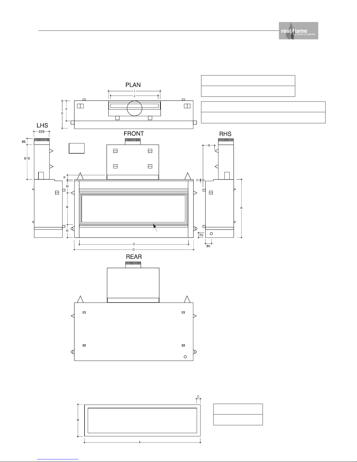
DIMENSIONS
Landscape 1000
ABCDEF GH
855 467 1000 1160 415 270 150 20
IJKLMN
755 505 65 30 178 190
Landscape 1000 Trim
ABC
1100 467 50
Gas
70mm
90mm
50mm Stand Offs
Powe r
25mm Stand Offs
100mm
Stand Offs
Lifting
Handles
Tr im
Fixing
channel
for plaster
DIMENSIONS
Landscape 1600
ABCDEF
855 467 1600 1760 415 270
GH I J K L MN
150 20 755 700 65 30 178 190
7
Gas
Gas
60mm
115mm
Powe r
Landscape 1600 Trim
ABC
1700 467 50
Tr im

Cowl types
Flue
• The Landscape is a balanced flue space heater.
• It can be installed with the flue terminating with a horizontal or vertical cowl to suit the
application.
LANDSCAPE MODEL (continued)
8
Vertical top
termination
Vertical top
termination
90° Bend
45° Bend
300mm 600mm 1200mm
RF/HZ
Horizontal rear
termination
Model Inner Outer
1000 100 180
1600 150 225
AB
265 370
315 315
90° Bend
AB
260 200
270 270
45° Bend
Flue Components
A A
B
B

LANDSCAPE MODEL (continued)
Timber Frame Installation Procedure
Step 1
Construct the base for the unit. Ensure base is adequate for the weight of the fire.
Step 2
Call for delivery of the unit, position on the base and fit off gather, flues and termination. Connect
gas and power.
FLUE
GATHER
GAS
POWER
Termination outside
(Horizontal shown)
C
Vertical Termination
9
Base of unit to
centre of flue
1000 = 1695
1600 = 1637
Back of unit to
centre of flue
(Excluding 25mm
standoff)
1000 = 160
1600 = 122
 Loading...