

Real Flame HYBRID 850, HYBRID 1000, HYBRID 1500, HYBRID 1800, HYBRID 3300 Installation & Operating Manual

HYBRID
DECORATIVE FIREBOX
INSTALLATION & OPERATING MANUAL
Hybrid fire boxes are approved to be installed as a zero clearance
firebox and are designed to operate on Natural Gas and Propane (LPG)
gases ONLY.
Approval Number: GMK10099
Installed primarily as a decorative appliance. Not certified as a Space Heater.
VERSION 2

2
WARRANTY INFORMATION
The benefits provided to you under the following warranty are in addition to any other rights and remedies available to
you under the law.
1. Warranty
If:
(a) during the first 15 years from the date of purchase (Firebox Warranty Period), there is a defect in the firebox of the
Real Flame Gas Burner; or
(b) during the first 2 years from the date of purchase (Parts Warranty Period), there is a defect in the gas valves or
other parts of the Real Flame Gas Burner,
due to improper workmanship or material, Real Flame will replace or repair the Real Flame Gas Burner without
charge. Any replacement product is warranted only for the time remaining on the original Firebox Warranty
Period or the Parts Warranty Period as relevant.
2. Registration
You must register to receive the benefit of this warranty by completing the warranty registration on our website
(www.realflame.com.au) or completing and mailing the attached registration card within 30 days of purchase of
your Real Flame Gas Burner (or, if the Real Flame Gas Burner is fitted to a new home, within 30 days of the date
of settlement of purchase of such new home).
3. Exclusions
Real Flame is not obliged to replace or repair the Real Flame Gas Burner under clause 1 if:
(a) it has been improperly stored, installed, connected, used, operated or repaired, or damaged, abused, tampered
with, altered (without our written approval), or not maintained in strict accordance with our installation and
operating instructions; or
(b) it has been installed in an outdoor setting.
4. Limit of Liability
The warranty provided under this warranty is limited to replacement or repair of the Real Flame Gas Burner only,
at our option. To the extent permitted by law, Real Flame excludes liability for consequential loss or any other loss
or damage caused to property or persons arising from any cause whatsoever, and damage arising from normal
wear and tear.
5. Claiming under the Warranty
In order to claim under this warranty you must, within the Firebox Warranty Period or the Parts Warranty Period
(as relevant), contact Real Flame, providing the original proof of purchase and the details below:
Supplier Name___________________________________________________________________________
Date Of Purchase / settlement of property if new home _________________
Model / Serial Number_______________________
This warranty does not cover the cost of claiming under the warranty or transporting the Real Flame Gas Burner to and
from the supplier.
Our goods come with guarantees that cannot be excluded under the Australian Consumer Law. You are entitled to a
replacement or refund for a major failure and for compensation for any other reasonably foreseeable loss or damage.
You are also entitled to have the goods repaired or replaced if the goods fail to be of acceptable quality and the failure
does not amount to a major failure.
If you would like to speak to someone about your Real Flame Gas Burner or claiming under this warranty, please
contact the Real Flame Service Warranty Desk on 03 8706 2000.
Real Flame Pty Ltd ACN 006 311 155
Head Office: 1340 Ferntree Gully Road, Scoresby 3179
Telephone: 03 8706 2000 Facsimile: 03 8706 2001
INSTALLATION NOTICE
The installation of this appliance is only to be carried out by an authorised person in accordance with the
Manufacturer’s Instructions, local gas fitting regulations, AS/NZS 5601.1-2013 installation code for gas
burning appliances and any other relevant statutory regulations.
In all cases the installation of this appliance shall meet the requirements as set out in AS/NZS 5601.1-2013.
NOTE: A slight smell may be apparent for the first few hours of use. This is due to the heat resistant
paint curing. It is recommended to open windows in the room for the first lighting of the fire. In some
instances a slight discolouration may occur inside the firebox. This is a normal condition and is not
covered by warranty.
WARNING
This firebox has a naked flame, care should be taken when it is operating if children or the infirm are
in close proximity. A safety screen is recommended if constant supervision is not possible. It is
recommended that a secondary guard complying with AS-NZS2286 be installed.
SERVICING
It is recommended you service your gas fire every 2 years as a minimum.
IMPORTANT SAFETY NOTICES
DO NOT PLACE ARTICLES ON OR AGAINST THIS APPLIANCE.
DO NOT USE OR STORE FLAMMABLE MATERIAL NEAR THE APPLIANCE.
DO NOT SPRAY AEROSOLS IN THE VICINITY OF THIS APPLIANCE WHILST IT IS IN OPERATION.
CARE MUST BE TAKEN TO ENSURE THAT ANY RETURN AIR REGISTER OR EXHAUST SYSTEM
DOES NOT ADVERSLEY AFFECT THE OPERATION OF THE APPLIANCE OR DRAUGHT OF
CHIMNEY OR FLUE.
DO NOT MODIFY THIS APPLIANCE.
THIS APPLIANCE IS DESIGNED TO OPERATE WITH LUMINOUS FLAMES. THIS MAY EXHIBIT
SLIGHT CARBON DEPOSITS.
VENTILATION REQUIREMENTS
MODEL SIZE EFFECTIVE VENTILATION
HYBRID 850 32,000mm
2
HYBRID 1000 50,000mm
2
HYBRID 1500 72,000mm
2
HYBRID 1800 72,000mm
2
HYBRID 3300 144,000mm
2
3
NOT INTENDED AS A FIREPLACE INSERT.

CONTENTS
Contents ..................................................................................................................4
Data Plate.................................................................................................................5
Zero Clearance Modular Installation & Dimensions ................................................6
Dimensions Hybrid 850............................................................................................7
Dimensions Hybrid 1000..........................................................................................8
Dimensions Hybrid 1500..........................................................................................9
Dimensions Hybrid 1800........................................................................................10
Dimensions Hybrid 3300........................................................................................11
Zero Clearance Modular Installation
Timber Frame Installation.......................................................................12
Installation Check List.............................................................................13
Lighting/Testing and Failure Procedure.................................................................14
Flue Requirements (Standard) ..............................................................................15
Flue Requirements (Power Flue Kit) ......................................................................16
Optional Power Flue...............................................................................................17
Introduction.............................................................................................17
Installation...............................................................................................17
Motor Clearance .....................................................................................20
Frameout.................................................................................................21
Motor.......................................................................................................21
Internal Motor..........................................................................................22
External Motor ........................................................................................22
Dimensions.............................................................................................23
Troubleshooting Electronic Ignition and Power Flue System ................25
Wiring Diagram.......................................................................................27
Parts ................................................................................................................28
Marble Bases & Fronts...........................................................................................29
Real Flame contact information .............................................................................32
4

DATA PLATE (Affixed to the base of the unit for reference to gas pressure & consumption)
5
Hybrid 850 & Hybrid Signature 850
Fitted with Magiglo 540 or 540EI burner
Gas Injector Size (mm) TPP N.G.C. (Mj/Hr)
Natural Gas 2 x 2.25 0.80 kPa 37
ULPG 2 x 1.10 2.60 kPa 33
Hybrid 1000 & Hybrid Signature 1000
Fitted with Magiglo 750 or 750EI burner
Gas Injector Size (mm) TPP N.G.C. (Mj/Hr)
Natural Gas 3 x 1.85 0.75 kPa 39
ULPG 3 x 0.95 2.55 kPa 34
Hybrid 1500 & Hybrid Signature 1500
Fitted with 1000 or 1000EI burner
Gas Injector Size (mm) TPP N.G.C. (Mj/Hr)
Natural Gas 3 x 2.25 0.75 kPa 49
ULPG 3 x 1.10 2.60 kPa 49
Fitted with 1200 burner
Gas Injector Size (mm) TPP N.G.C. (Mj/Hr)
Natural Gas 4 x 2.20 0.80 kPa 55
ULPG 4 x 0.95 2.55 kPa 48
Hybrid 1800 & Hybrid Signature 1800
Fitted with 1400 or 1400EI burner
Gas Injector Size (mm) TPP N.G.C. (Mj/Hr)
Natural Gas 4 x 2.25 0.85 kPa 60
ULPG 4 x 0.95 2.55 kPa 48
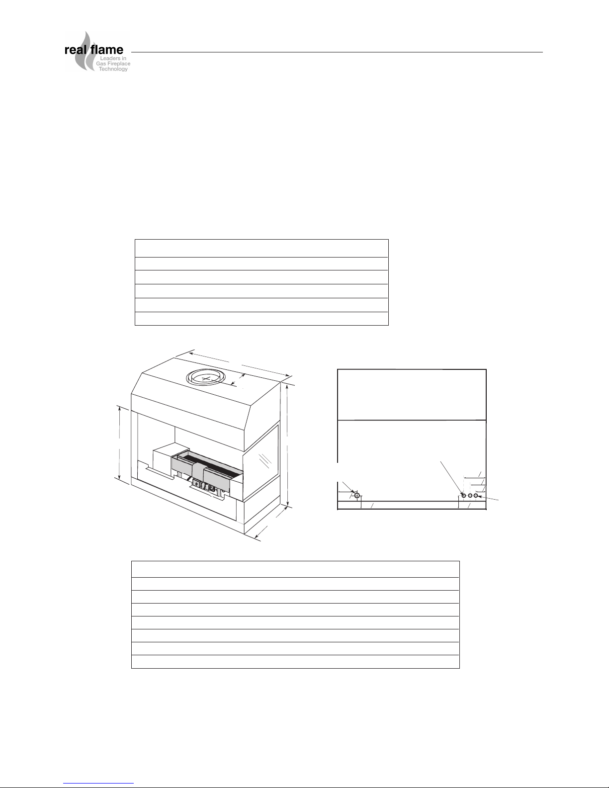
ZERO CLEARANCE MODULAR INSTALLATION
• The Firebox is designed to be installed into a new frame out as shown on page 12.
• The fire can be installed at ground level or raised to what ever height is required providing
the flue length is 3.6 meters or more.
• The firebox can sit directly onto a wooden surface.
• The Firebox requires twin skin flue with an AGA approved cowl (or optional Power Flue –
refer pages 17 to 27)
• The control valve on the Firebox is an electronic ignition system and as such, electrical
work is required.
Overall Dimensions (in mm)
MODEL Size Inner Outer
HYBRID 850 200 250
HYBRID 1000 250 300
HYBRID 1500 300 350
HYBRID 1800 300 350
HYBRID 3300 300 x2 350 x2
POWER FLUE (optional) BEFORE MOTOR 150 200
AFTER MOTOR 150 200
Flue Sizes (in mm)
Right Hand Hybrid shown
MODEL A B C D E
850 920 950 450 570 155
1000 920 1100 450 570 155
1500 1000 1600 450 500 190
1800 1140 1900 450 500 190
3300 1135 3400 450 500 190
D
B
E
A
C
12mm Gas Line
Inlet Point
Connection to Power Flue
or electronic ignition
(Optional)
125c
90c
Power Lead
(Optional)
REAR OF FIREBOX
130c
100c
70c
90c
6
J
J
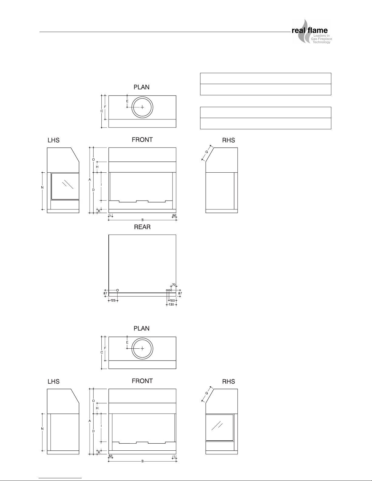
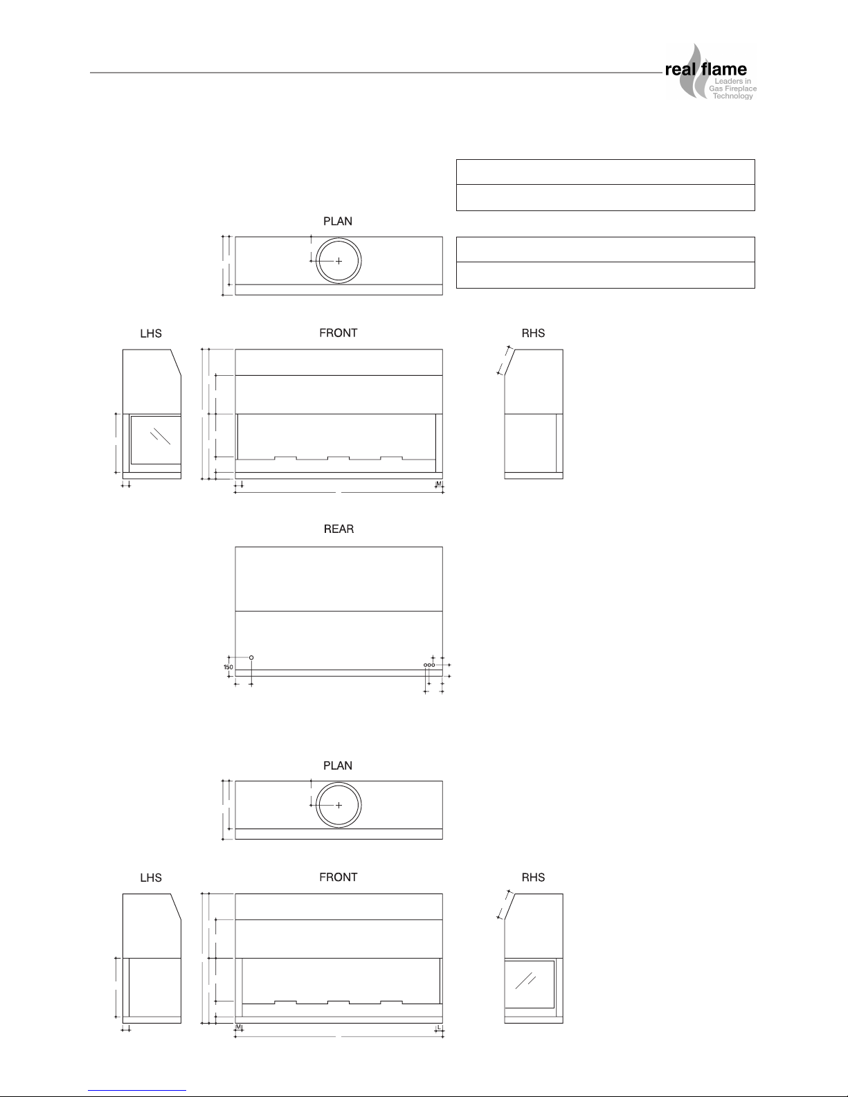
DIMENSIONS
Hybrid 850 - Left Hand Model
Hybrid 850 - Right Hand Model
AB CDEF GH
920 950 450 570 165 335 230 150
IJKLMNO
400 120 50 10 50 520 350
7
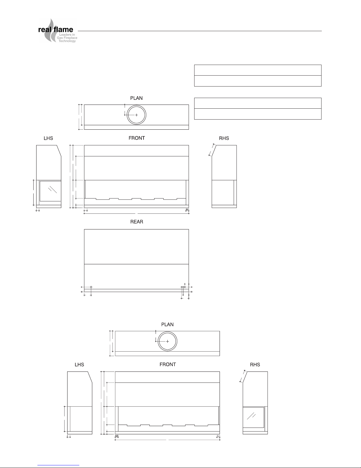
DIMENSIONS
Hybrid 1000 - Left Hand Model
Hybrid 1000 - Right Hand Model
AB CDEF GH
920 1100 450 570 165 335 230 150
IJKLMNO
400 120 50 10 50 520 350
8
F
C
A
D
J
I
N
G
K
L
B
M
E
O
H
125
87
130
10 0
70
F
C
A
D
J
I
N
G
K
B
M
E
O
H
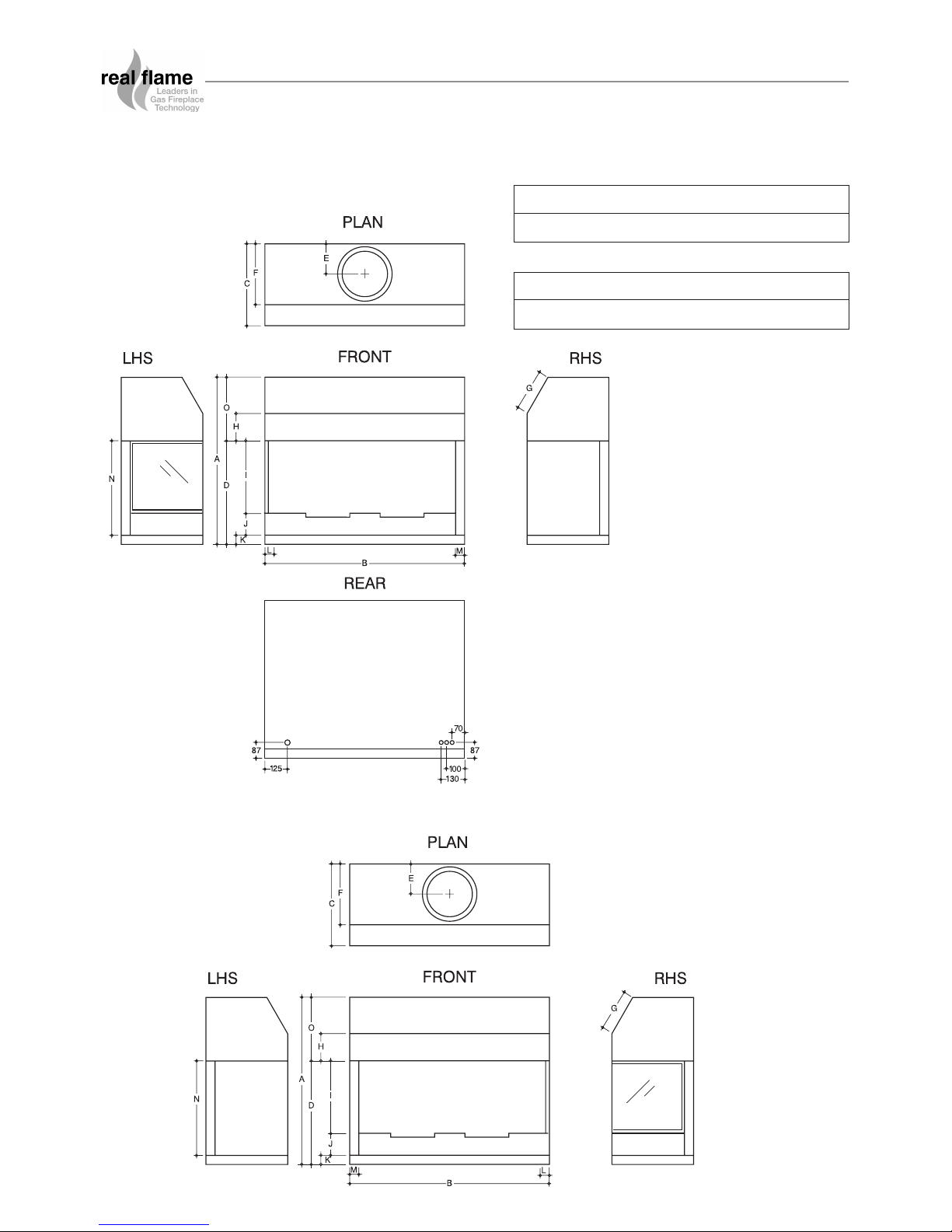
DIMENSIONS
Hybrid 1500 - Left Hand Model
Hybrid 1500 - Right Hand Model
AB CDEF GH
1000 1600 450 500 190 370 215 300
IJKLMNO
330 120 50 10 50 450 500
9
F
C
A
D
J
I
N
G
K
L
B
M
E
O
H
87
125
87
130
10 0
70
F
C
A
D
J
I
N
G
K
B
M
E
O
H
DIMENSIONS
Hybrid 1800 - Left Hand Model
Hybrid 1800 - Right Hand Model
AB CDEF GH
1135 1900 450 500 190 370 215 435
IJKLMNO
330 120 50 10 50 450 635
10
 Loading...