

Real Flame HEATSEEKER 600, HEATSEEKER 700, HEATSEEKER 850, HEATSEEKER 1000 Installation & Operating Manual

HEATSEEKER
®
GAS FIREBOX
INSTALLATION & OPERATING MANUAL
The Heatseeker Gas Firebox is approved to be installed into a masonary
fireplace and as a zero clearance firebox and is designed to operate on
Natural Gas and Propane (LPG) gases ONLY. Approval Number 6094.
Installed primarily as a decorative appliance. Not certified as a Space Heater.
VERSION 13

2
WARRANTY
Provided your Real Flame gas fire is installed in strict accordance with our installation instructions, the
firebox is unconditionally guaranteed for ten years and all other parts for twelve months from date of
purchase.
This unconditional warranty covers part and labour at our discretion taking into consideration normal wear
and tear and does not cover fires installed in outdoor settings.
WARNING
This firebox has a naked flame, care should be taken when it is operating if children or the infirm are
in close proximity. A safety screen is recommended if constant supervision is not possible.
IMPORTANT SAFETY NOTICE
DO NOT PLACE ARTICLES ON OR AGAINST THIS APPLIANCE.
DO NOT USE OR STORE FLAMMABLE MATERIAL NEAR THE APPLIANCE.
DO NOT SPRAY AEROSOLS IN THE VICINITY OF THIS APPLIANCE WHILST IT IS IN OPERATION.
CARE MUST BE TAKEN TO ENSURE THAT ANY RETURN AIR REGISTER OR EXHAUST SYSTEM
DOES NOT ADVERSLEY AFFECT THE OPERATION OF THE APPLIANCE OR DRAUGHT OF
CHIMNEY OR FLUE.
INSTALLATION NOTICE
The installation of this appliance is only to be carried out by an authorised person in accordance
with the Manufacturer’s Instructions, local gas fitting regulations, AG601 installation code for gas
burning appliances and any other relevant statutory regulations.
In all cases the installation of this appliance shall meet the requirements as set out in AS5601/AG601.
NOTE: A slight smell may be apparent for the first few hours of use. This is due to the heat resistant
paint curing. It is recommended to open windows in the room for the first lighting of the fire. In some
instances a slight discolouration may occur inside the firebox. This is a normal condition and is not
covered by warranty.
VENTILATION REQUIREMENTS
MODEL EFFECTIVE VENTILATION
600 18,000 sq mm
700 18,000 sq mm
850 32,000 sq mm
1000 32,000 sq mm

CONTENTS
Contents ..................................................................................................................3
Data Plate.................................................................................................................4
Inbuilt model installation diagrams..........................................................................5
Dimensions Heatseeker 600....................................................................................6
Dimensions Heatseeker 700....................................................................................7
Dimensions Heatseeker 850....................................................................................8
Dimensions Heatseeker 1000..................................................................................9
Dimensions Heatseeker 600 ZC ............................................................................10
Dimensions Heatseeker 700 ZC ............................................................................11
Dimensions Heatseeker 850 ZC ............................................................................12
Dimensions Heatseeker 1000 ZC ..........................................................................13
Inbuilt Installation Procedure .................................................................................14
Zero Clearance Timber Frame Installation ............................................................16
Zero Clearance Model Components .....................................................................17
Zero Clearance Model Assembly...........................................................................18
Zero Clearance Model Installation Procedure .......................................................19
Lighting instructions...............................................................................................20
Commissioning ......................................................................................................21
Optional Power Flue...............................................................................................22
Introduction.............................................................................................22
Installation...............................................................................................23
Motor Clearance .....................................................................................25
Frameout.................................................................................................26
Motor exploded view ..............................................................................26
Internal Motor..........................................................................................27
External Motor ........................................................................................28
Wiring Diagram.......................................................................................29
Parts List .................................................................................................29
Troubleshooting Electronic Ignition and Power Flue System ...............................30
Parts kit ................................................................................................................32
Flue termination (cowls) regulations .....................................................................33
Marble trim installation instructions .......................................................................34
Mantlepiece installation instructions......................................................................35
Electrical diagram ..................................................................................................36
Real Flame contact information .............................................................................40
3
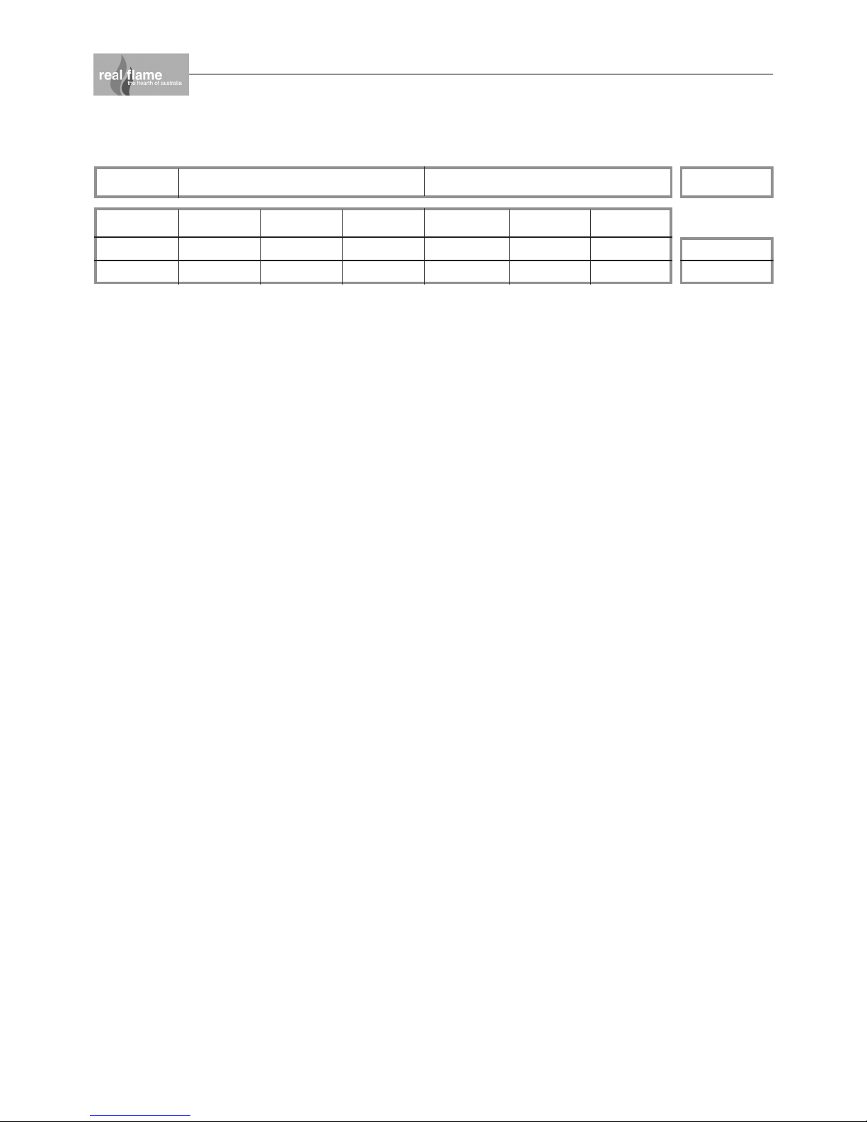
MODEL NATURAL GAS LPG UNIT
Inj. Size MJ/Hr P.T.P Inj. Size MJ/Hr P.T.P
540 2 x 2.2 37 0.8 kPa 2 x 1.1 31 2.6 kPa
750 2 x 2.5 39 0.63 kPa 2 x 1.2 36 2.55 kPa
600 & 700
850 & 1000
4
DATA PLATE (Affixed to burner)

5
HEATSEEKER INBUILT MODEL
• Unit installed into an existing “working” fireplace requires an AGA approved 225mm gas
cowl and chimney plate fixed to the chimney top.
• If the fireplace is not a “working” fireplace, then the applicable flue to the model being
installed should be installed using a gather, single skin flue and AGA approved gas cowl.
• If the flue is to be exposed, or enclosed with any combustible material, the appropriate
approved twin skin flue and gas cowl is required.
MODEL A B C D E F G H I
600 730 370 605 610 370 740 670 75 15
700 830 370 605 710 370 840 670 75 15
850 980 370 605 860 370 990 670 75 15
1000 1130 370 605 1005 370 1140 670 75 15
Overall Dimensions (in mm)
OFF
P
I
L
O
T
6
E
J
H
H
FRONT - 3 SIDEDFRONT - 4 SIDED
E
B
A
D
C
F
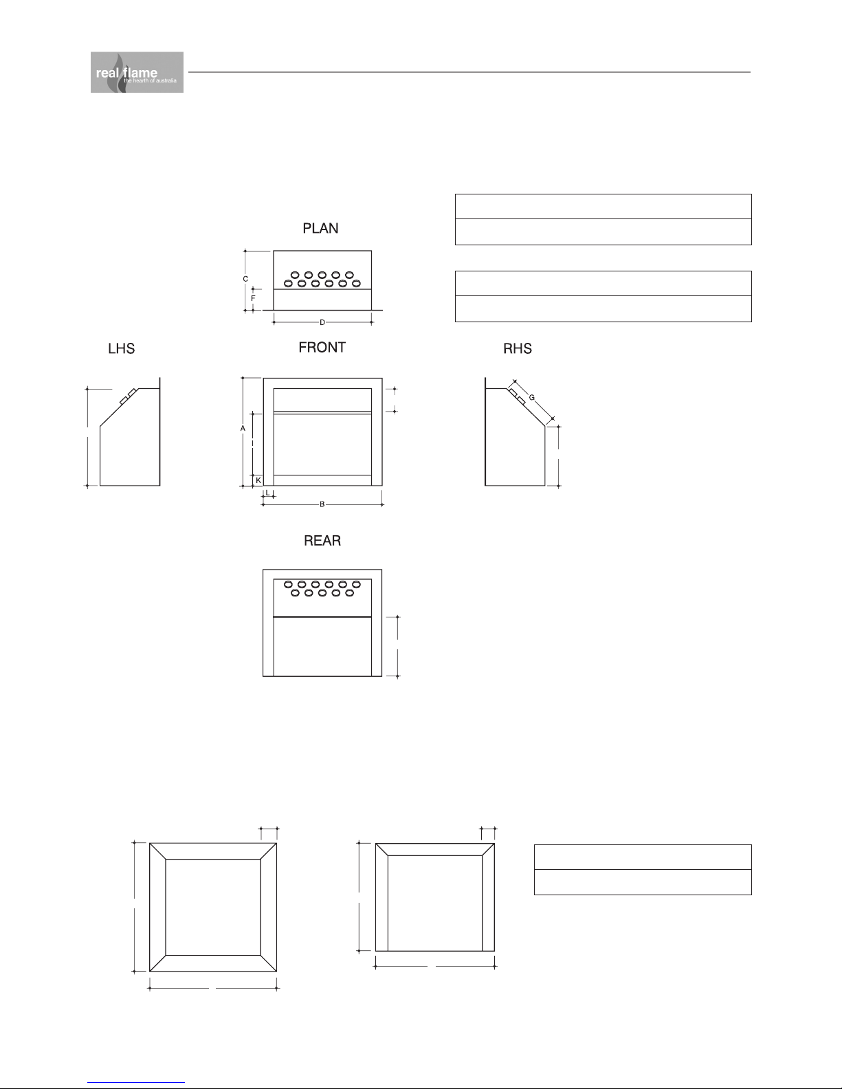
DIMENSIONS
Heatseeker 600
Heatseeker 600 Trim
AB CDEF
790 800 740 670 100 75
AB CDEF GH
670 740 370 610 605 130 330 365
IJKL
380 150 65 60

E
H
J
FRONT - 3 SIDEDFRONT - 4 SIDED
E
B
A
D
C
F
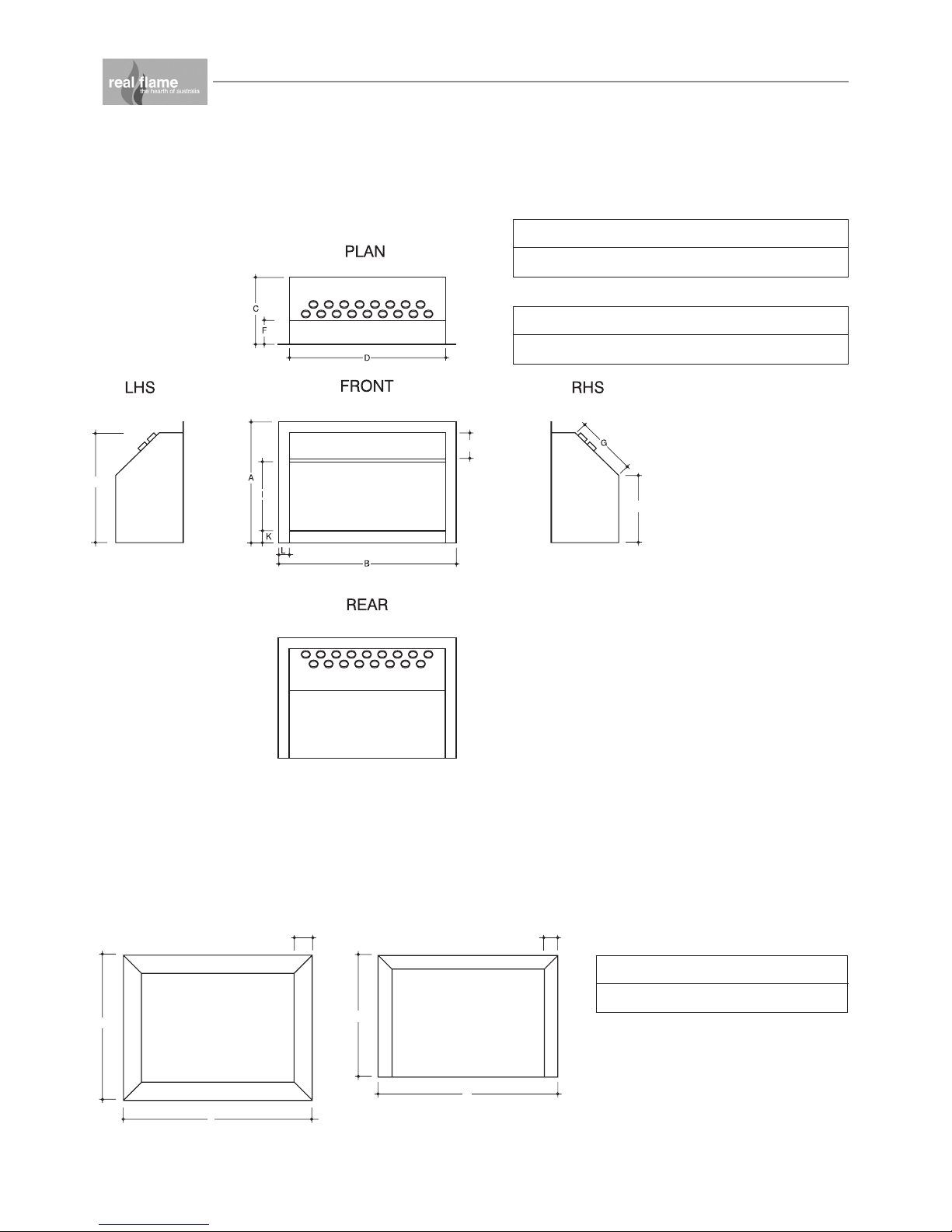
DIMENSIONS
Heatseeker 700
Heatseeker 700 Trim
AB CDEF
890 800 840 670 100 75
AB CDEF GH
665 830 370 710 605 130 330 365
IJKL
380 150 65 60
7
E
H
J
FRONT - 3 SIDEDFRONT - 4 SIDED
E
B
A
D
C
F
DIMENSIONS
Heatseeker 850
Heatseeker 850 Trim
AB CDEF
1040 800 990 670 100 75
AB CDEF GH
665 980 370 860 605 130 330 365
IJKL
380 150 65 60
8

E
J
H
E
B
A
FRONT - 3 SIDEDFRONT - 4 SIDED
D
C
F
DIMENSIONS
Heatseeker 1000
Heatseeker 1000 Trim
AB CDEF
1190 800 1140 670 100 75
AB CDEF GH
665 1130 370 1005 605 130 330 365
IJKL
380 150 65 60
9

J
FRONT - 3 SIDEDFRONT - 4 SIDED
E
B
A
D
C
F
DIMENSIONS
Heatseeker 600 ZC
Heatseeker 600 ZC Trim
AB CDEF
790 800 740 670 100 75
AB CDEF GH
665 730 415 675 - 235 650 -
IJKL
380 150 65 60
10

J
FRONT - 3 SIDEDFRONT - 4 SIDED
E
B
A
D
C
F
DIMENSIONS
Heatseeker 700 ZC
Heatseeker 700 ZC Trim
AB CDEF
890 800 840 670 100 75
AB CDEF GH
665 830 415 775 - 235 650 -
IJKL
380 150 65 60
11

J
FRONT - 3 SIDEDFRONT - 4 SIDED
E
B
A
D
C
F
DIMENSIONS
Heatseeker 850 ZC
Heatseeker 850 ZC Trim
AB CDEF
1040 800 990 670 100 75
AB CDEF GH
665 985 415 930 - 235 650 -
IJKL
380 150 65 60
12
 Loading...