

Real Flame EXURO IO1000 Installation & Operating Manual

EXURO IO1000
INSTALLATION & OPERATING MANUAL
Important: The appliance shall be installed in accordance with;
· Local gas fitting regulations
· Municipal building codes
· AS/NZS 5601.1:2013, Gas installations
· Any other relevant statutory regulations.
· TO BE INSTALLED ONLY BY AN AUTHORIZED PERSON
· THIS APPLIANCE MUST NOT BE INSTALLED OR USED INDOORS
INSTRUCTIONS MUST BE LEFT WITH THE CONSUMER AND THE
CONSUMER TO RETAIN THEM FOR FUTURE REFERENCE.
Approval Number: GMK10105
VERSION 2
2
WARRANTY INFORMATION
The benefits provided to you under the following warranty are in addition to any other rights and remedies available to
you under the law.
1. Warranty
If:
(a) during the first 2 years from the date of purchase (Parts and Labour Warranty Period), there is a defect in the
firebox and all other parts; or
(b) during the first 5 years from the date of purchase (Parts Only Warranty Period), there is a defect in the firebox
only,
due to improper workmanship or material, Real Flame will replace or repair the Real Flame Gas Burner without
charge. Any replacement product is warranted only for the time remaining on the original Parts and Labour
Warranty Period or the Parts Only Warranty Period as relevant.
2. Registration
You must register to receive the benefit of this warranty by completing the warranty registration on our website
(www.realflame.com.au) or completing and mailing the attached registration card within 30 days of purchase of
your Real Flame Gas Burner (or, if the Real Flame Gas Burner is fitted to a new home, within 30 days of the date
of settlement of purchase of such new home).
3. Exclusions
Real Flame is not obliged to replace or repair the Real Flame Gas Burner under clause 1 if:
(a) it has been improperly stored, installed, connected, used, operated or repaired, or damaged, abused, tampered
with, altered (without our written approval), or not maintained in strict accordance with our installation and
operating instructions.
4. Limit of Liability
The warranty provided under this warranty is limited to replacement or repair of the Real Flame Gas Burner only,
at our option. To the extent permitted by law, Real Flame excludes liability for consequential loss or any other loss
or damage caused to property or persons arising from any cause whatsoever, and damage arising from normal
wear and tear.
5. Claiming under the Warranty
In order to claim under this warranty you must, within the Parts and Labour Warranty Period or the Parts Only
Warranty Period (as relevant), contact Real Flame, providing the original proof of purchase and the details below:
Supplier Name___________________________________________________________________________
Date Of Purchase / settlement of property if new home _________________
Model / Serial Number_______________________
This warranty does not cover the cost of claiming under the warranty or transporting the Real Flame Gas Burner to and
from the supplier.
Our goods come with guarantees that cannot be excluded under the Australian Consumer Law. You are entitled to a
replacement or refund for a major failure and for compensation for any other reasonably foreseeable loss or damage.
You are also entitled to have the goods repaired or replaced if the goods fail to be of acceptable quality and the failure
does not amount to a major failure.
If you would like to speak to someone about your Real Flame Gas Burner or claiming under this warranty, please
contact the Real Flame Service Warranty Desk on 03 8706 2000.
Real Flame Pty Ltd ACN 006 311 155
Head Office: 1340 Ferntree Gully Road, Scoresby 3179
Telephone: 03 8706 2000 Facsimile: 03 8706 2001

INSTALLATION NOTICE
The installation of this appliance is only to be carried out by an authorised person in accordance
with the Manufacturer’s Instructions, local gas fitting regulations, AS/NZS5601.1.2013
installation code for gas burning appliances and any other relevant statutory regulations.
Do not modify this appliance.
In all cases the installation of this appliance shall meet the requirements as set out in
AS/NZS5601.1.2013.
NOTE: A slight smell may be apparent for the first few hours of use. This is due to the heat resistant
paint curing. It is recommended to open windows in the room for the first lighting of the fire. In some
instances a slight discolouration may occur inside the firebox. This is a normal condition and is not
covered by warranty.
IMPORTANT SAFETY NOTICE
DO NOT PLACE ARTICLES ON OR AGAINST THIS APPLIANCE.
DO NOT USE OR STORE FLAMMABLE MATERIAL NEAR THE APPLIANCE.
DO NOT SPRAY AEROSOLS IN THE VICINITY OF THIS APPLIANCE WHILST IT IS IN OPERATION.
CARE MUST BE TAKEN TO ENSURE THAT ANY RETURN AIR REGISTER OR EXHAUST SYSTEM
DOES NOT ADVERSLEY AFFECT THE OPERATION OF THE APPLIANCE OR DRAUGHT OF
CHIMNEY OR FLUE.
IT IS NOT RECOMMENDED TO OPERATE THE FIRE WITH THE FASCIA PANELS REMOVED.
3
SERVICING
It is recommended you service your gas fire every 2 years as a minimum.

CONTENTS
Contents ..................................................................................................................4
Data Plate.................................................................................................................5
Basic Operation .......................................................................................................6
Removing the Fascia................................................................................................8
Pilot Flame & Burner Positioning.............................................................................9
Maintenance & Cleaning..........................................................................................9
Installation ..............................................................................................................10
Warning...................................................................................................10
Product Description................................................................................11
Dimensions.............................................................................................11
Power Supply..........................................................................................12
Creating the Cavity .................................................................................12
Clearances to Combustibles ..................................................................12
Wall Cladding around fire.......................................................................13
Minimum Install Height...........................................................................13
Types of Installation ................................................................................13
Corner Installations.................................................................................15
Laying Gas Pipe .....................................................................................16
Fixing the Fire into Cavity .......................................................................17
Connecting the Gas Pipe .......................................................................17
Connecting the power supply and power switch...................................18
Testing of the power switch and spark ignition......................................18
Checking Operating Pressure ................................................................19
Assembly of the Glass Feature...............................................................20
Fitting the Fascia ....................................................................................20
Placement of ceramic stones .................................................................21
Optional Weather Cover .........................................................................21
Electrical Schematic...............................................................................................22
Exploded View .......................................................................................................23
Gas Conversion .....................................................................................................24
Real Flame contact information .............................................................................28
4
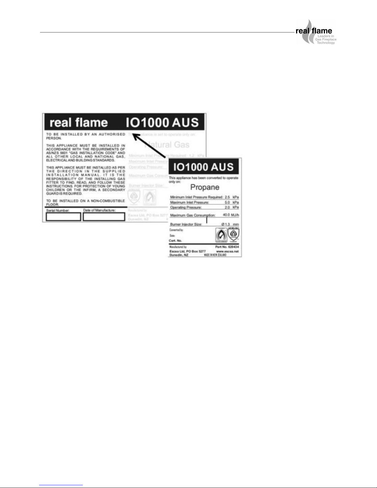
DATA PLATE (The dataplate for this appliance, containing technical information and specifications can
be found to the right of the control tray, near the base of the fire. To access this, the fascia must first be
removed.
5
BASIC OPERATION
The IO1000 is operated by the switch located on the right hand side outer edge of the fascia. The
basic operations possible are ON/OFF.
Before operating the fire, ensure that the power transformer is plugged into the mains wall socket
and turned on, and the supply is turned on.
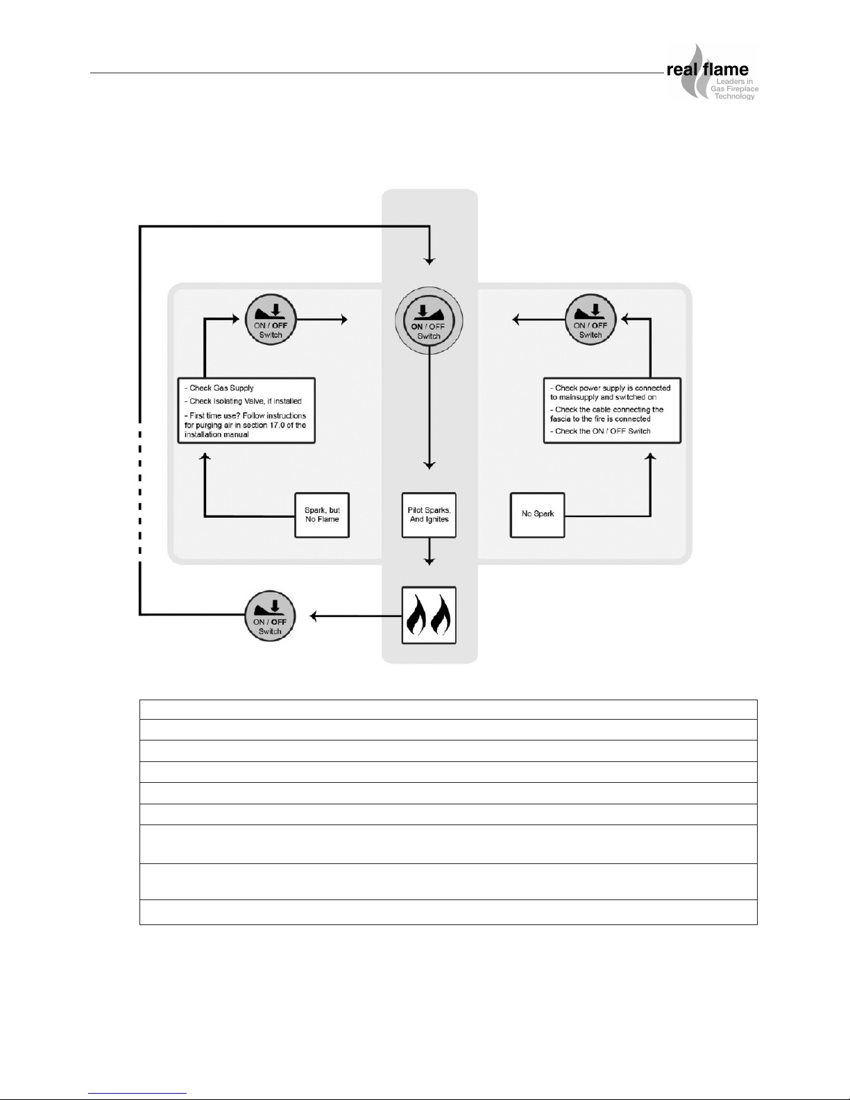
Ignition:
To turn the fire on push the ON/OFF rocker switch to the on position. The ignition unit will start
sparking and the pilot and burners will ignite almost immediately.
In the event of no gas, the ignition unit will attempt to try to light up to 3 times before shutting
down.
Turning off the fire:
To turn the fire off, simply flick the ON/OFF rocker switch to the off position. This will shut down the
gas flow to the pilot flame and both burners.
Please ensure the gas supply is also turned off, and as an extra safety please turn off the main
power supply at the house.
CAUTIONS
• Due to its high operating temperature, the appliance should be located out of traffic and
away from furniture and draperies.
• Children and adults should be alerted to the hazards of the high surface temperature, which
could cause burns or clothing ignition.
• Young children should be carefully supervised when they are in the same room as the
appliance.
• Clothing or other flammable materials must not be placed on or near the appliance.
6
ON/OFF
Power
Switch
7
BASIC OPERATION
Propane ULPG Natural Gas
Min. Inlet Pressure 2.5 kPa 2.5 kPa 1.00 kPa
Max Inlet Pressure 5.0 kPa 5.0 kPa 5.00 kPa
Manifold Pressure 2.0 kPa 2.2 kPa 1.00 kPa
Front Burner Jet size Ø1.3 Ø1.25 Ø4.0
Rear Burner Jet size Ø1.3 Ø1.25 Ø4.0
Front Burner Aeration Hole 11mm x 2 off per burner 11mm x 2 off per burner Ø5mm x 2 holes
(NO COLLAR FITTED) (NO COLLAR FITTED) Collar must be fitted -1 off per burner
Rear Burner Aeration Hole 11mm x 2 off per burner 11mm x 2 off per burner Ø5mm x 2 holes
(NO COLLAR FITTED) (NO COLLAR FITTED) Collar must be fitted -1 off per burner
Mj/hour 40 40 49
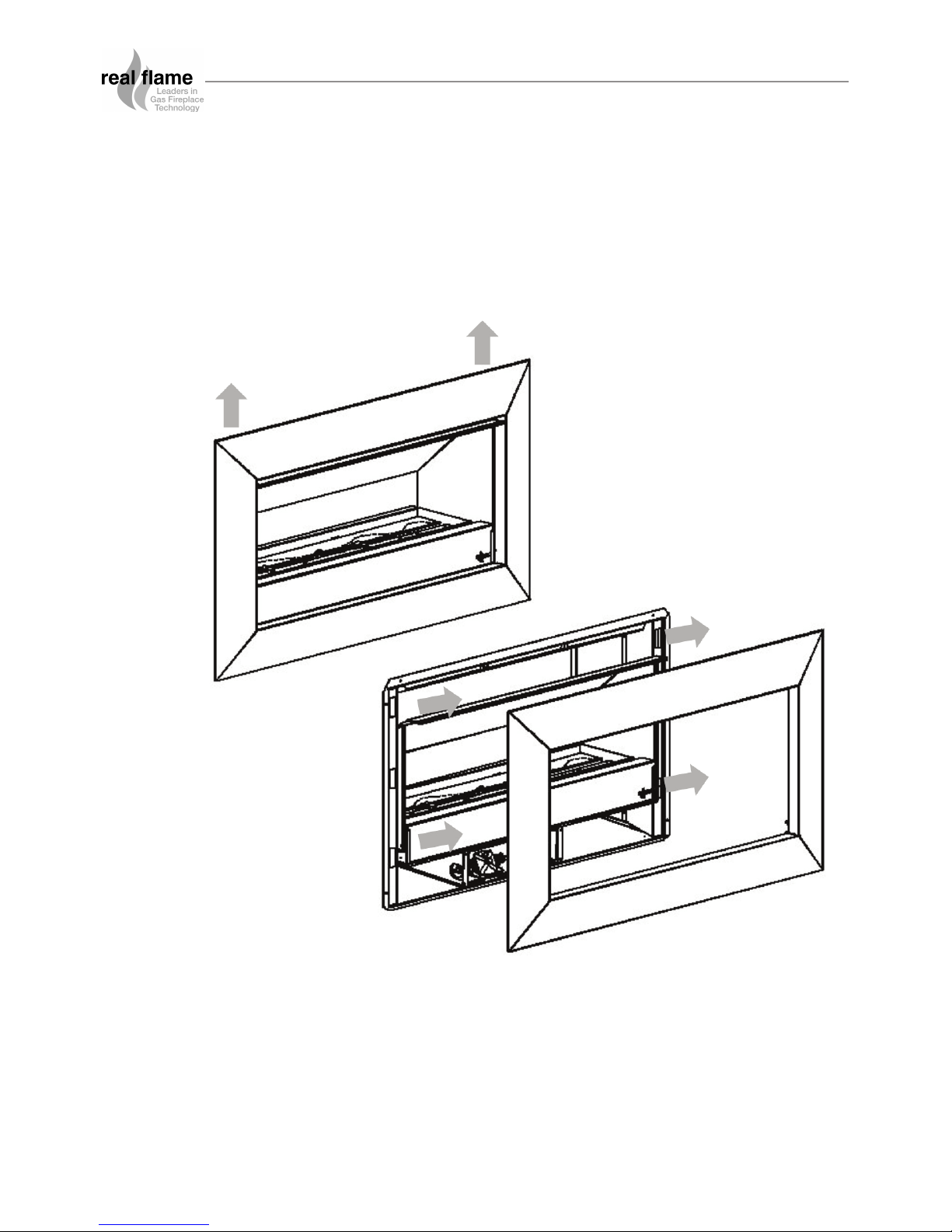
REMOVING THE FASCIA
8
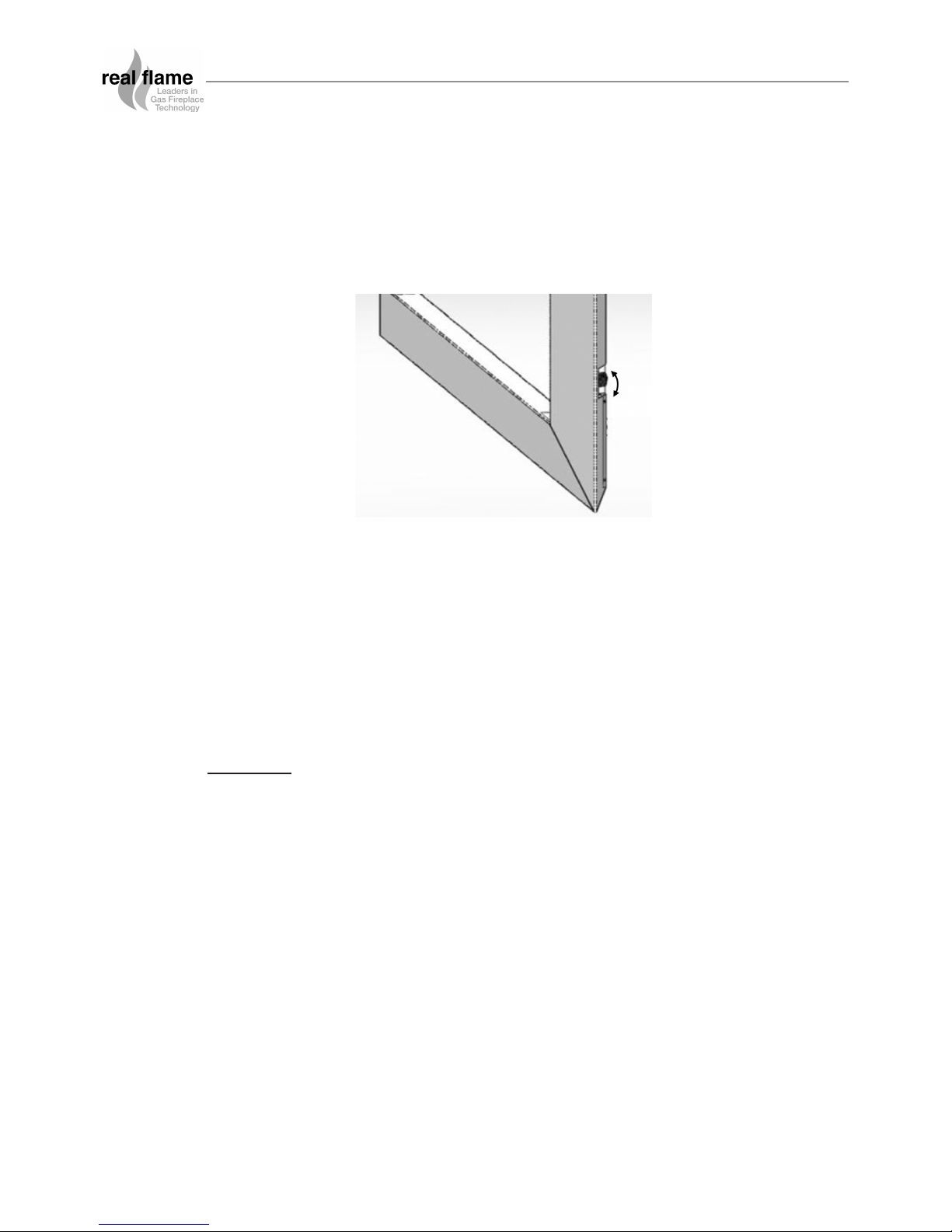
The IO1000 Stainless Steel fascia is attached to the fire by four ‘hooks’ on the corners of the
fascia. If you need to remove the fascia, lift it upwards and slowly pull it away from the fire in the
same motion.
After the fascia has been unhooked, the short electrical cable attaching the fire to the fascia can
now be unplugged and the fascia can be completely detached.
MAINTENANCE AND CLEANING
9
The unit must be cold before starting any form of maintenance or cleaning.
The glass can be removed and cleaned using standard window cleaner. Be careful not to scratch
the rear of the glass which has a black screen print on it.
To clean the weather cover, warm soapy water should be used.
Cleaning of the burners and ceramic stones can be carried out using a brush and a dry cloth and
should be done at least annually. This will remove carbon or soot build-up. Periodically the pilot
and burners should be checked visually for carbon and soot build-up, a consistent flame and
clean burning.
Fascia:
The Fascia is the visible surround of your Real Flame IO1000 Gas Fireplace and must be treated
carefully to prevent unsightly marks from tarnishing the visual quality of the product. Some
marking over time is inevitable however, so the following directions will assist you in getting the
maximum enjoyment from it.
NEVER EVER RUB THE FASCIA.
The outside of a Real Flame Fascia must only be cleaned with a soft microfibre cloth. If heavier
cleaning is required for the likes of grease or stubborn fingerprint removal we recommend the use
of Steel Kleen brand Ezi Wipes for stainless steel fascias only, and warm soapy water for powder
coated Fascias. These wipes have been tested and produce very satisfying results, when used
correctly. For heavier marks, try the following:
For Stainless Steel Fascias:
• Products such as Steel Kleen ezi wipes applied to the fascia gently in the direction of the
grain have been tested and produce satisfying results when used correctly.
For Powder Coated Fascias:
• Use warm soapy water and a clean soft microfibre cloth to gently clean any marks.
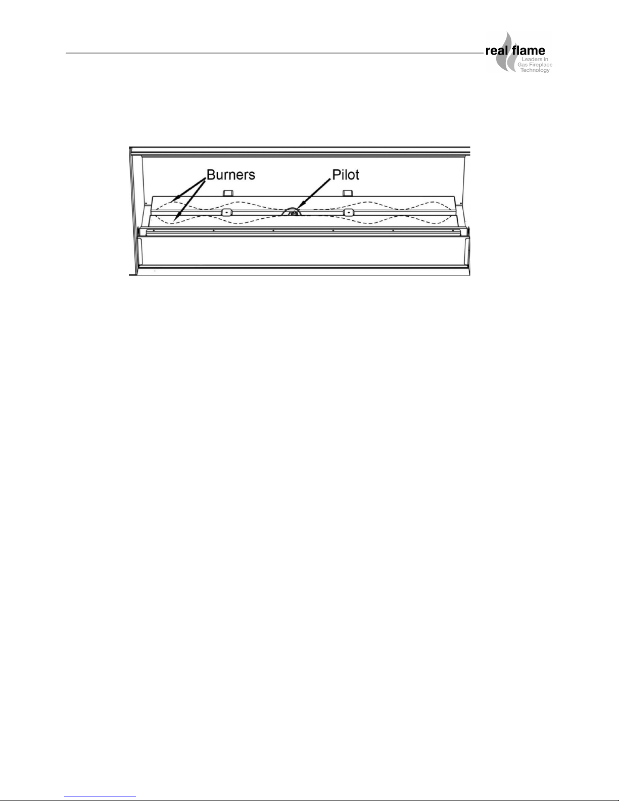
PILOT FLAME AND BURNER POSITIONING
 Loading...