

Real Flame ELEGANCE 850, ELEGANCE 1000, ELEGANCE 1800, ELEGANCE 3300 Installation & Operating Manual
ELEGANCE®, SIMPLICITY®,
PURE VISION
®
DECORATIVE FIREBOXES
INSTALLATION & OPERATING MANUAL
Elegance – Simplicity – Pure Vision fire boxes are approved to be
installed as a zero clearance firebox and are designed to operate on
Natural Gas and Propane (LPG) gases ONLY.
Approval Numbers: 6094 & GSCS20018
Installed primarily as a decorative appliance. Not certified as a Space Heater.
VERSION 20
2
WARRANTY
Provided your Real Flame gas fire is installed in strict accordance with our installation instructions, the
firebox is unconditionally guaranteed for ten years and all other parts for twelve months from date of
purchase.
This unconditional warranty covers parts and labour at our discretion taking into consideration normal wear
and tear and does not cover fires installed in outdoor settings.
INSTALLATION NOTICE
The installation of this appliance is only to be carried out by an authorised person in accordance with the
Manufacturer’s Instructions, local gas fitting regulations, AG601 installation code for gas burning
appliances and any other relevant statutory regulations.
In all cases the installation of this appliance shall meet the requirements as set out in AS5601/AG601.
NOTE: A slight smell may be apparent for the first few hours of use. This is due to the heat resistant
paint curing. It is recommended to open windows in the room for the first lighting of the fire. In some
instances a slight discolouration may occur inside the firebox. This is a normal condition and is not
covered by warranty.
WARNING
This firebox has a naked flame, care should be taken when it is operating if children or the infirm are
in close proximity. A safety screen is recommended if constant supervision is not possible.
IMPORTANT SAFETY NOTICE
DO NOT PLACE ARTICLES ON OR AGAINST THIS APPLIANCE.
DO NOT USE OR STORE FLAMMABLE MATERIAL NEAR THE APPLIANCE.
DO NOT SPRAY AEROSOLS IN THE VICINITY OF THIS APPLIANCE WHILST IT IS IN OPERATION.
CARE MUST BE TAKEN TO ENSURE THAT ANY RETURN AIR REGISTER OR EXHAUST SYSTEM DOES
NOT ADVERSLEY AFFECT THE OPERATION OF THE APPLIANCE OR DRAUGHT OF CHIMNEY OR FLUE.
VENTILATION REQUIREMENTS
MODEL SIZE EFFECTIVE VENTILATION
ELEGANCE 850 32,000mm
2
ELEGANCE 1000 50,000mm
2
ELEGANCE 1800 72,000mm
2
ELEGANCE 3300 144,000mm
2
SIMPLICITY 850 32,000mm
2
SIMPLICITY 1000 50,000mm
2
SIMPLICITY 1800 72,000mm
2
SIMPLICITY 3300 144,000mm
2
PURE VISION 850 32,000mm
2
PURE VISION 1000 50,000mm
2
PURE VISION 1800 72,000mm
2
PURE VISION 3300 144,000mm
2

CONTENTS
Contents ..................................................................................................................3
Data Plate.................................................................................................................4
Zero Clearance Modular Installation & Dimensions ................................................5
Dimensions Elegance 850 .......................................................................................6
Dimensions Elegance 1000 .....................................................................................7
Dimensions Elegance 1800 .....................................................................................8
Dimensions Elegance 3300 .....................................................................................9
Dimensions Simplicity 850.....................................................................................10
Dimensions Simplicity 1000...................................................................................11
Dimensions Simplicity 1800...................................................................................12
Dimensions Simplicity 3300...................................................................................13
Dimensions Pure Vision 850 ..................................................................................14
Dimensions Pure Vision 1000 ................................................................................15
Dimensions Pure Vision 1800 ................................................................................16
Dimensions Pure Vision 3300 ................................................................................17
Zero Clearance Modular Installation
Elegance & Simplicity Timber Frame Installation ..................................18
Pure Vision Timber Frame Installation ...................................................19
Installation Check List ............................................................................................20
Lighting/Testing and Failure Procedure.................................................................21
Flue Requirements (Standard) ..............................................................................22
Flue Requirements (Power Flue Kit) ......................................................................23
Optional Power Flue...............................................................................................24
Introduction.............................................................................................24
Installation...............................................................................................24
Motor Clearance .....................................................................................27
Frameout.................................................................................................28
Motor exploded view ..............................................................................28
Internal Motor..........................................................................................29
External Motor ........................................................................................30
Flue Terminations ...................................................................................31
Wiring Diagram.......................................................................................32
Troubleshooting Electronic Ignition and Power Flue System ...............................33
Parts List ................................................................................................................35
Trims & Marble Options .........................................................................................36
Real Flame contact information .............................................................................40
3

MODEL SIZE N.G LPG NG LPG NG LPG
ELEGANCE 850 2 x 2.2 2 x 1.1 37 31 0.08 2.60 6094 540
ELEGANCE 1000 2 x 2.5 2 x 1.2 39 36 0.43 2.55 6094 750
ELEGANCE 1800 4 x 2.8 4 x 0.95 63 52 0.70 2.54 GSCS20018 1400
ELEGANCE BOX 1
3300
4 x 2.8 4 x 0.95 63 52 0.70 2.54 GSCS20018 1400
ELEGANCE BOX 2 4 x 2.8 4 x 0.95 63 52 0.70 2.54 GSCS20018 1400
SIMPLICITY 850 2 x 2.2 2 x 1.1 37 31 0.08 2.60 6094 540
SIMPLICITY 1000 2 x 2.5 2 x 1.2 39 36 0.43 2.55 6094 750
SIMPLICITY 1800 4 x 2.8 4 x 0.95 63 52 0.70 2.54 GSCS20018 1400
SIMPLICITY BOX 1
3300
4 x 2.8 4 x 0.95 63 52 0.70 2.54 GSCS20018 1400
SIMPLICITY BOX 2 4 x 2.8 4 x 0.95 63 52 0.70 2.54 GSCS20018 1400
PURE VISION 850 2 x 2.2 2 x 1.1 37 31 0.08 2.60 6094 540
PURE VISION 1000 2 x 2.5 2 x 1.2 39 36 0.43 2.55 6094 750
PURE VISION 1800 4 x 2.8 4 x 0.95 63 52 0.70 2.54 GSCS20018 1400
PURE VISION BOX1
3300
4 x 2.8 4 x 0.95 63 52 0.70 2.54 GSCS20018 1400
PURE VISION BOX2 4 x 2.8 4 x 0.95 63 52 0.70 2.54 GSCS20018 1400
INJECTOR Mj/Hr TPP APPROVAL No. BURNER
MODEL
4
DATA PLATE (Affixed to the base of the unit for reference to gas pressure & consumption)

ZERO CLEARANCE MODULAR INSTALLATION
• The Firebox is designed to be installed into a new frame out as shown on pages 18 & 19.
• The fire can be installed at ground level or raised to what ever height is required providing
the flue length is 2.7 meters or more.
• The firebox can sit directly onto a wooden surface.
• The Firebox requires twin skin flue with an AGA approved cowl (or optional Power Flue –
refer pages 23 to 34)
• The control valve on the Firebox is an electronic ignition system and as such, electrical
work is required.
5
Overall Dimensions (in mm)
MODEL Size Inner Outer
ELEGANCE 850 200 250
ELEGANCE 1000 250 300
ELEGANCE 1800 300 350
ELEGANCE 3300 300 x2 350 x2
SIMPLICITY 850 200 250
SIMPLICITY 1000 250 300
SIMPLICITY 1800 300 350
SIMPLICITY 3300 300 x2 350 x2
PURE VISION 850 200 250
PURE VISION 1000 250 300
PURE VISION 1800 300 350
PURE VISION 3300 300 x2 350 x2
POWER FLUE (optional) BEFORE MOTOR 150 200
AFTER MOTOR 150 200
Flue Sizes (in mm)
MODEL A B C D E
850 920 950 450 570 155
1000 920 1100 450 570 155
1800 1140 1900 450 500 190
3300 1135 3400 450 500 190
D
B
E
A
C
12mm Gas Line
Inlet Point
Connection to Power Flue
or electronic ignition
(Optional)
125c
90c
Power Lead
(Optional)
REAR OF FIREBOX
130c
100c
70c
90c
6
FRONT - 3 SIDEDFRONT - 4 SIDED
B
A
E
D
C
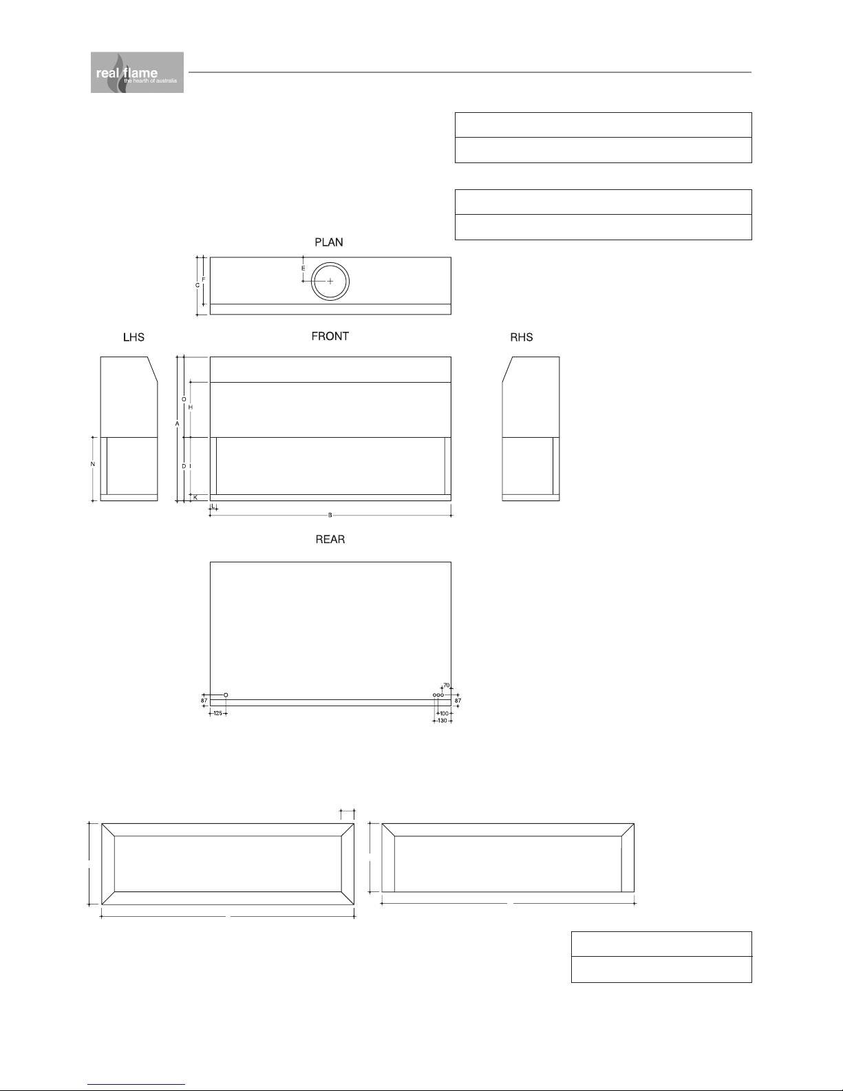
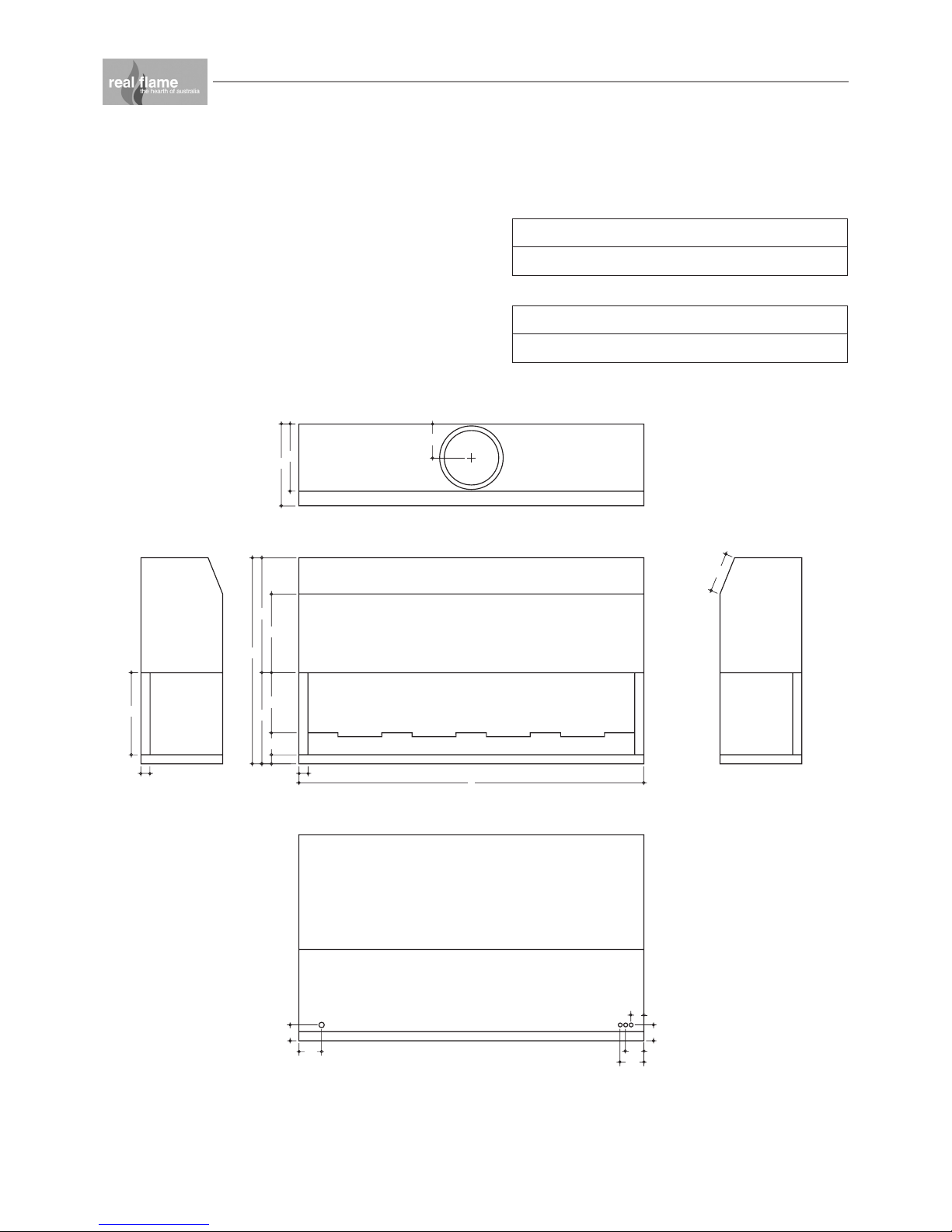
DIMENSIONS
Elegance 850
Elegance 850 Trim
AB CDEF GH
920 950 450 570 165 335 230 150
IJKLMNO
520 - 50 50 50 520 350
AB CDE
1043 713 1043 613 100
FRONT - 3 SIDEDFRONT - 4 SIDED
B
A
D
C
E
DIMENSIONS
Elegance 1000
Elegance 1000 Trim
AB CDE
1193 713 1193 613 100
7
AB CDEF GH
920 1100 450 570 165 335 230 150
IJKLMNO
520 - 50 50 50 520 350
8
E 1800
1:20
FRONT - 3 SIDEDFRONT - 4 SIDED
E
B
A
D
C
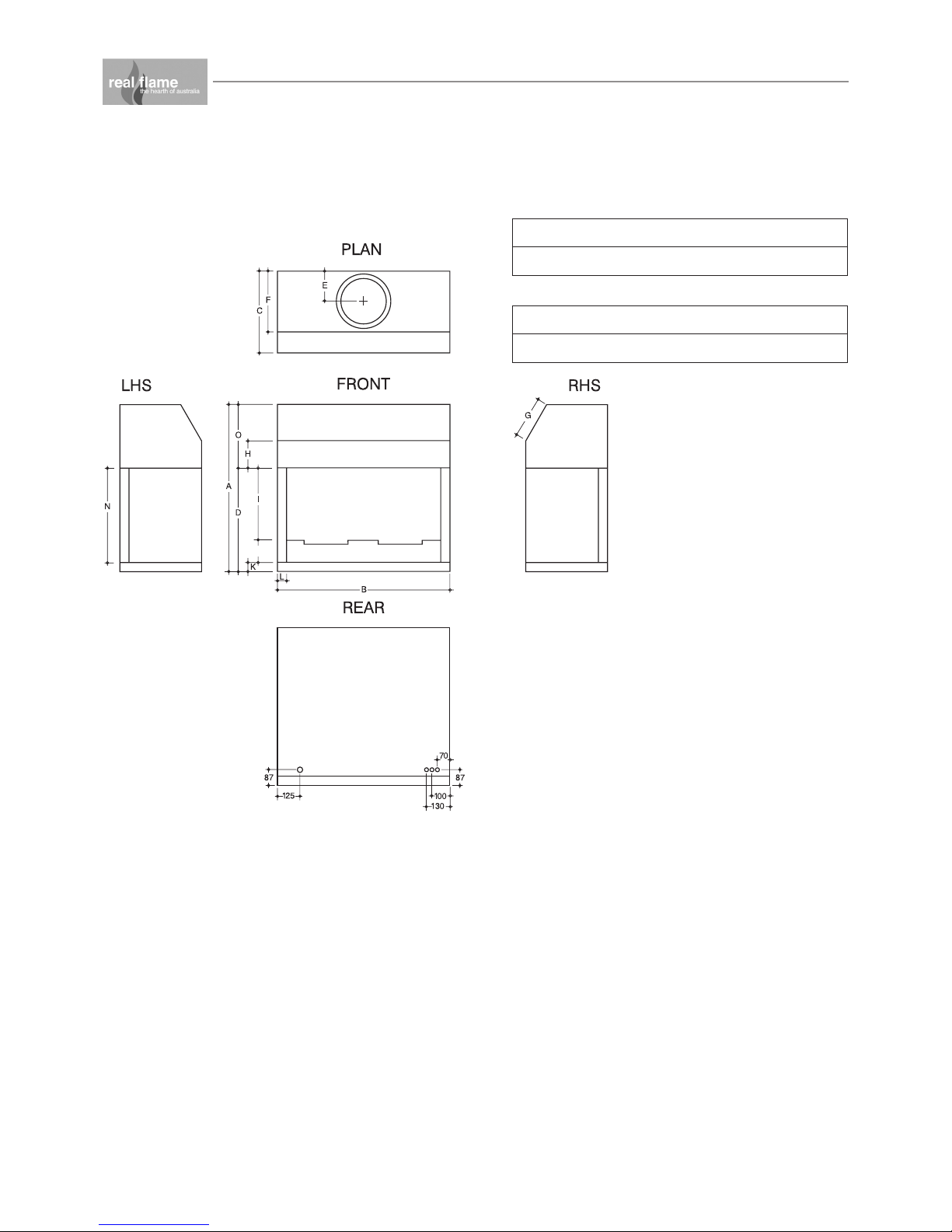
DIMENSIONS
Elegance 1800
Elegance 1800 Trim
AB CDEF GH
1135 1900 450 500 190 370 215 435
IJKLMNO
450 - 50 50 50 450 635
AB CDE
1990 640 1990 540 100
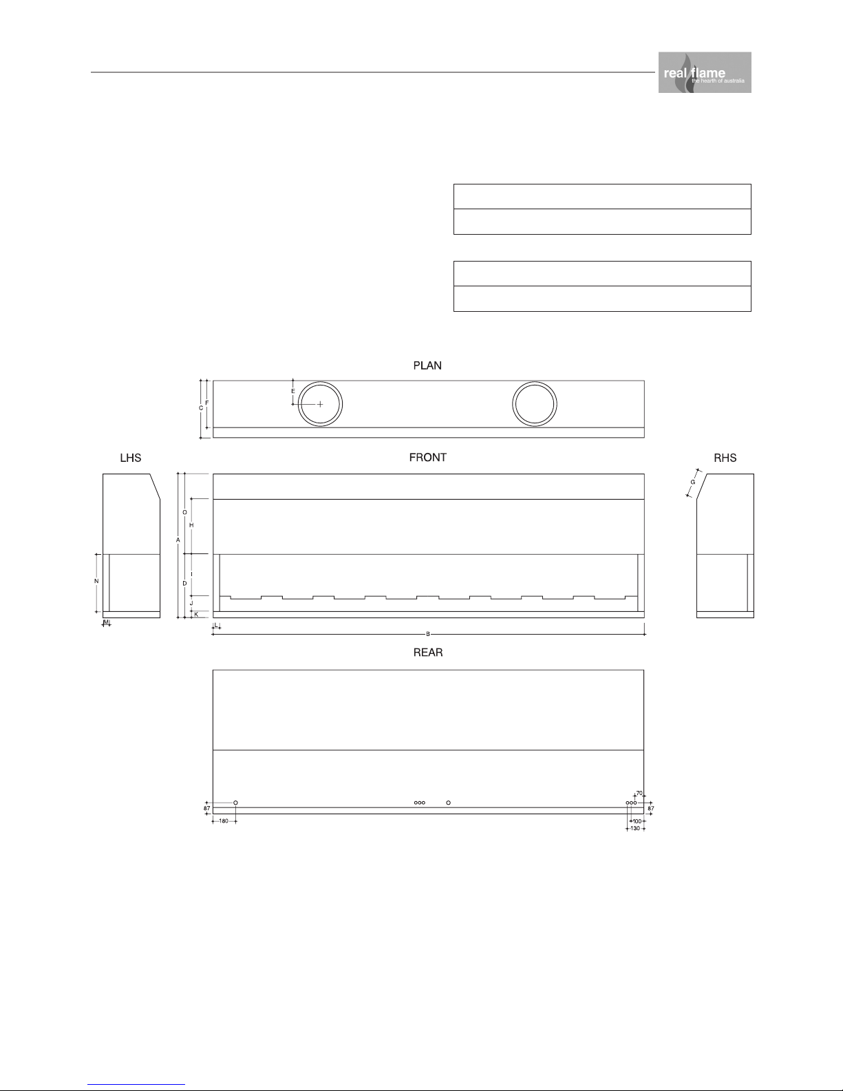
DIMENSIONS
Elegance 3300
AB CDEF GH
1135 3400 450 500 190 370 215 435
IJKLMNO
330 120 50 50 50 450 635
9
J
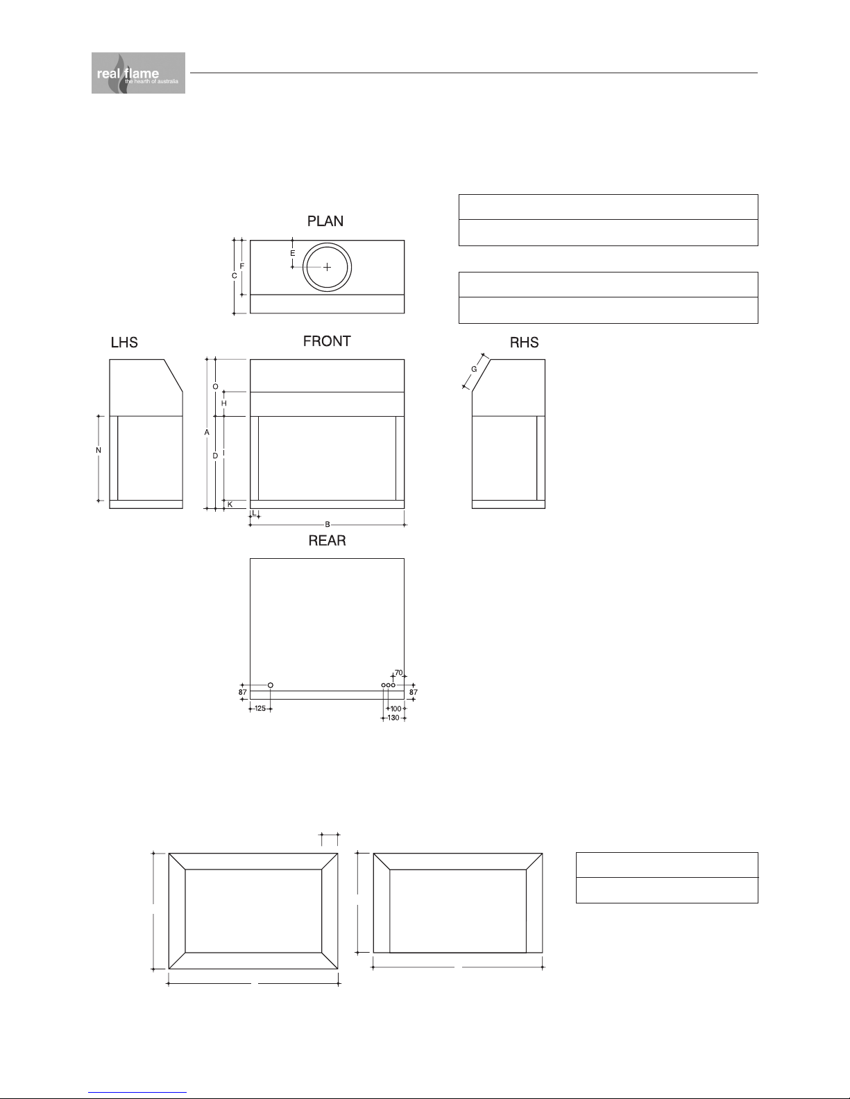
DIMENSIONS
Simplicity 850
AB CDEF GH
920 950 450 570 165 335 230 150
IJKLMNO
400 120 50 50 50 520 350
10
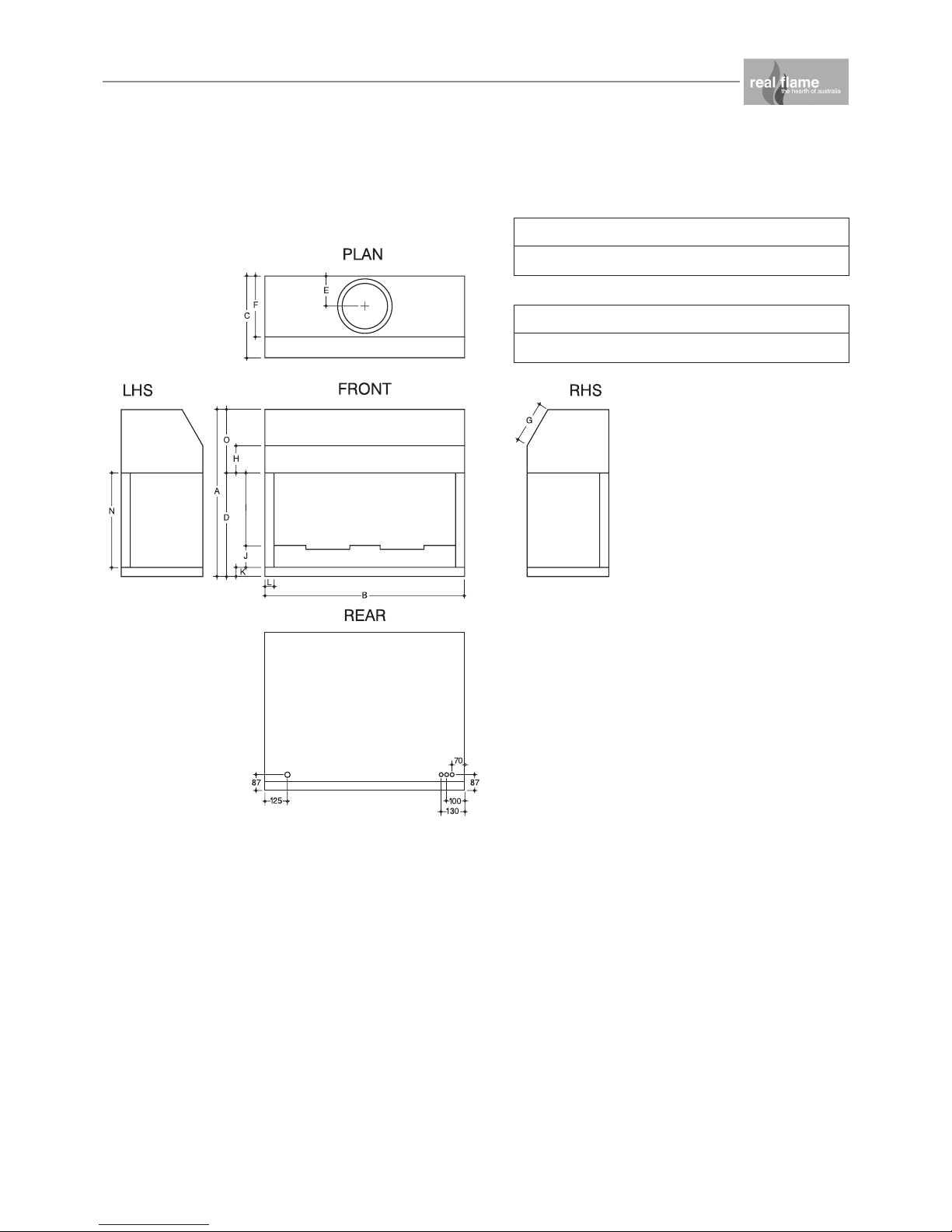
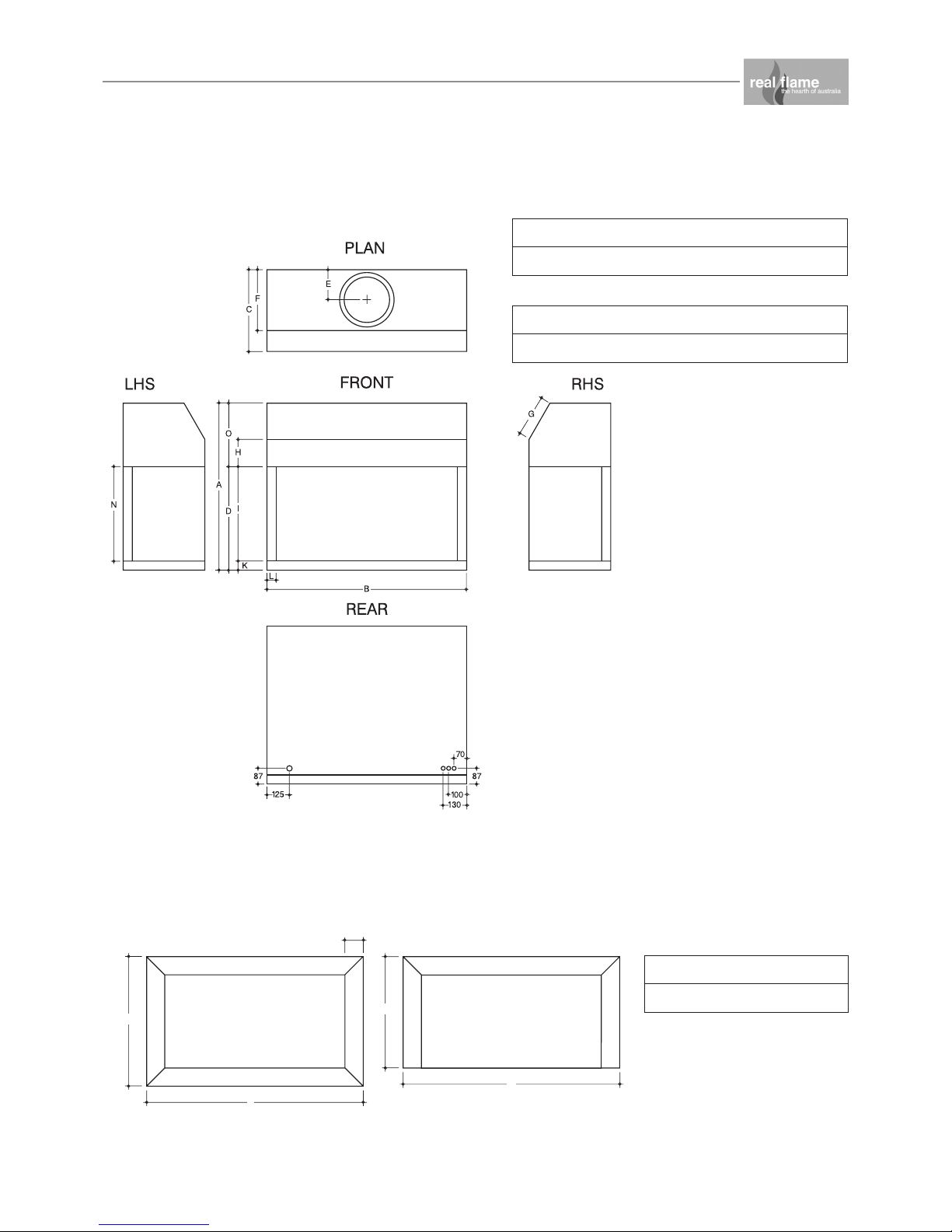
DIMENSIONS
Simplicity 1000
AB CDEF GH
920 1100 450 570 165 335 230 150
IJKLMNO
400 120 50 50 50 520 350
11
PLAN
FRONT
REAR
RHSLHS
F
C
A
D
J
I
N
G
K
L
B
M
E
O
H
87
12 5
87
130
10 0
70
DIMENSIONS
Simplicity 1800
AB CDEF GH
1135 1900 450 500 190 370 215 435
IJKLMNO
330 120 50 50 50 450 635
12
 Loading...