

Real Flame DOUBLE VISION, PURE VISION, SIMPLICITY Installation & Operating Manual
DOUBLE VISION
®
DECORATIVE FIREBOX
INSTALLATION & OPERATING MANUAL
The Double Vision gas firebox is approved to be installed as a zero
clearance firebox and is designed to operate on Natural Gas and
Propane (LPG) gases ONLY. Approval Number GMK10099.
VERSION 23

2
WARRANTY INFORMATION
The benefits provided to you under the following warranty are in addition to any other rights and remedies available to
you under the law.
1. Warranty
If:
(a) during the first 15 years from the date of purchase (Firebox Warranty Period), there is a defect in the firebox of the
Real Flame Gas Burner; or
(b) during the first 2 years from the date of purchase (Parts Warranty Period), there is a defect in the gas valves or
other parts of the Real Flame Gas Burner,
due to improper workmanship or material, Real Flame will replace or repair the Real Flame Gas Burner without
charge. Any replacement product is warranted only for the time remaining on the original Firebox Warranty
Period or the Parts Warranty Period as relevant.
2. Registration
You must register to receive the benefit of this warranty by completing the warranty registration on our website
(www.realflame.com.au) or completing and mailing the attached registration card within 30 days of purchase of
your Real Flame Gas Burner (or, if the Real Flame Gas Burner is fitted to a new home, within 30 days of the date
of settlement of purchase of such new home).
3. Exclusions
Real Flame is not obliged to replace or repair the Real Flame Gas Burner under clause 1 if:
(a) it has been improperly stored, installed, connected, used, operated or repaired, or damaged, abused, tampered
with, altered (without our written approval), or not maintained in strict accordance with our installation and
operating instructions; or
(b) it has been installed in an outdoor setting.
4. Limit of Liability
The warranty provided under this warranty is limited to replacement or repair of the Real Flame Gas Burner only,
at our option. To the extent permitted by law, Real Flame excludes liability for consequential loss or any other loss
or damage caused to property or persons arising from any cause whatsoever, and damage arising from normal
wear and tear.
5. Claiming under the Warranty
In order to claim under this warranty you must, within the Firebox Warranty Period or the Parts Warranty Period
(as relevant), contact Real Flame, providing the original proof of purchase and the details below:
Supplier Name___________________________________________________________________________
Date Of Purchase / settlement of property if new home _________________
Model / Serial Number_______________________
This warranty does not cover the cost of claiming under the warranty or transporting the Real Flame Gas Burner to and
from the supplier.
Our goods come with guarantees that cannot be excluded under the Australian Consumer Law. You are entitled to a
replacement or refund for a major failure and for compensation for any other reasonably foreseeable loss or damage.
You are also entitled to have the goods repaired or replaced if the goods fail to be of acceptable quality and the failure
does not amount to a major failure.
If you would like to speak to someone about your Real Flame Gas Burner or claiming under this warranty, please
contact the Real Flame Service Warranty Desk on 03 8706 2000.
Real Flame Pty Ltd ACN 006 311 155
Head Office: 1340 Ferntree Gully Road, Scoresby 3179
Telephone: 03 8706 2000 Facsimile: 03 8706 2001
INSTALLATION NOTICE
The installation of this appliance is only to be carried out by an authorised person in accordance
with the Manufacturer’s Instructions, local gas fitting regulations,
AS5601-2004 installation code for
gas burning appliances and any other relevant statutory regulations.
In all cases the installation of this appliance shall meet the requirements as set out in AS5601-2004.
Not intended for use as fireplace insert.
NOTE: A slight smell may be apparent for the first few hours of use. This is due to the heat resistant
paint curing. It is recommended to open windows in the room for the first lighting of the fire. In some
instances a slight discolouration may occur inside the firebox. This is a normal condition and is not
covered by warranty.
NOTE: The Double Vision Modular fire is primarily a decorative appliance and is not certified as
a space heater.
IMPORTANT SAFETY NOTICES
DO NOT PLACE ARTICLES ON OR AGAINST THIS APPLIANCE.
DO NOT USE OR STORE FLAMMABLE MATERIAL NEAR THE APPLIANCE.
DO NOT SPRAY AEROSOLS IN THE VICINITY OF THIS APPLIANCE WHILST IT IS IN OPERATION.
CARE MUST BE TAKEN TO ENSURE THAT ANY RETURN AIR REGISTER OR EXHAUST SYSTEM
DOES NOT ADVERSLEY AFFECT THE OPERATION OF THE APPLIANCE OR DRAUGHT OF
CHIMNEY OR FLUE.
DO NOT MODIFY THIS APPLIANCE.
THIS APPLIANCE IS DESIGNED TO OPERATE WITH LUMINOUS FLAMES. THIS MAY EXHIBIT
SLIGHT CARBON DEPOSITS.
VENTILATION REQUIREMENTS
MODEL SIZE EFFECTIVE VENTILATION
Double Vision 850 40,000 sq mm
WARNING
This firebox has a naked flame, care should be taken when it is operating if children or the infirm are
in close proximity. A safety screen is recommended if constant supervision is not possible. It is
recommended that a secondary guard complying with AS-NZS2286 be installed.
3
THIS IS PRIMARILY A DECORATIVE APPLIANCE AND IS NOT CERTIFIED AS A SPACE HEATER.
SERVICING
It is recommended you service your gas fire every 2 years as a minimum.

CONTENTS
Contents ..................................................................................................................4
Data Plate.................................................................................................................5
Firebox dimensions..................................................................................................6
Dimensions ..............................................................................................................7
Zero Clearance Timber Frame Installation ..............................................................8
Inbuilt Installation Procedure ...................................................................................9
Lighting pilot and main burner...............................................................................10
Tests to be carried out by installer .........................................................................11
Failure procedure...................................................................................................11
Maintenance...........................................................................................................12
Troubleshooting the Millivolt Gas System Control ................................................13
Service - Igniter and Burner ...................................................................................14
Parts Kit, Gas Control Assembly, Burner Assembly ..............................................15
Flue requirements ..................................................................................................16
Optional Power Flue...............................................................................................17
Introduction.............................................................................................17
Installation...............................................................................................17
Motor Clearance .....................................................................................20
Frameout.................................................................................................21
Motor.......................................................................................................21
Internal Motor..........................................................................................22
External Motor ........................................................................................22
Dimensions.............................................................................................23
Troubleshooting Electronic Ignition and Power Flue System ................25
Wiring Diagram.......................................................................................27
Real Flame contact information .............................................................................28
4
Gas Injector Size (mm) TPP N.G.C. (Mj/hr)
Natural Gas 2 x 2.80 0.87 kPa 54
ULPG 2 x 1.35 2.64 kPa 43
DATA PLATE (Affixed to the base of the unit for reference to gas pressure & consumption)
5
Double Vision and Double Vision Signature
Fitted with 540 Double Vision burner
Gas Injector Size (mm) TPP N.G.C. (Mj/hr)
Natural Gas 2 x 2.80 0.87 kPa 54
ULPG 2 x 1.35 2.64 kPa 43
Double Vision and Double Vision Signature
Fitted with 540 Double Vision Pattern burner
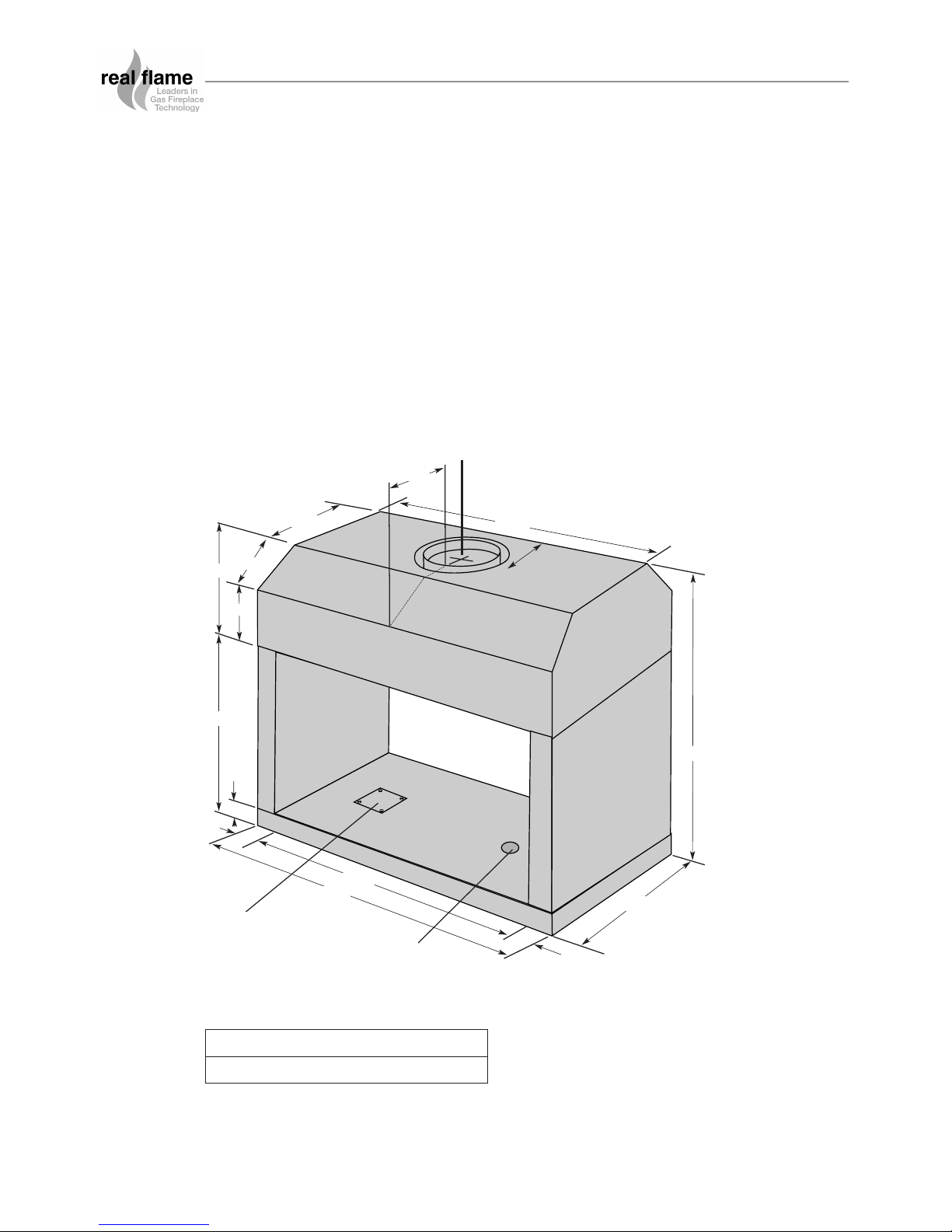
380mm
950mm
155mm
600mm
850mm
50mm
50mm
50mm
950mm
850mm
210mm
230mm
300mm
160mm
470mm
FLUE
Inner 225mm
Outer 275mm
COVER PLATE
FOR ELECTRONICS
GAS LINE INLET
DOUBLE VISION FIREBOX
• The Double Vision is designed to be installed into a new frame out as shown on page 6.
• The fire can be installed at ground level or raised to what ever height is required providing
the flue length is 2.7 meters or more.
• The firebox can sit directly onto a wooden surface.
• The Double Vision requires twin skin flue with an AGA approved cowl
• The control valve on the Double Vision is a millivolt system and as such, no electrical work
is required
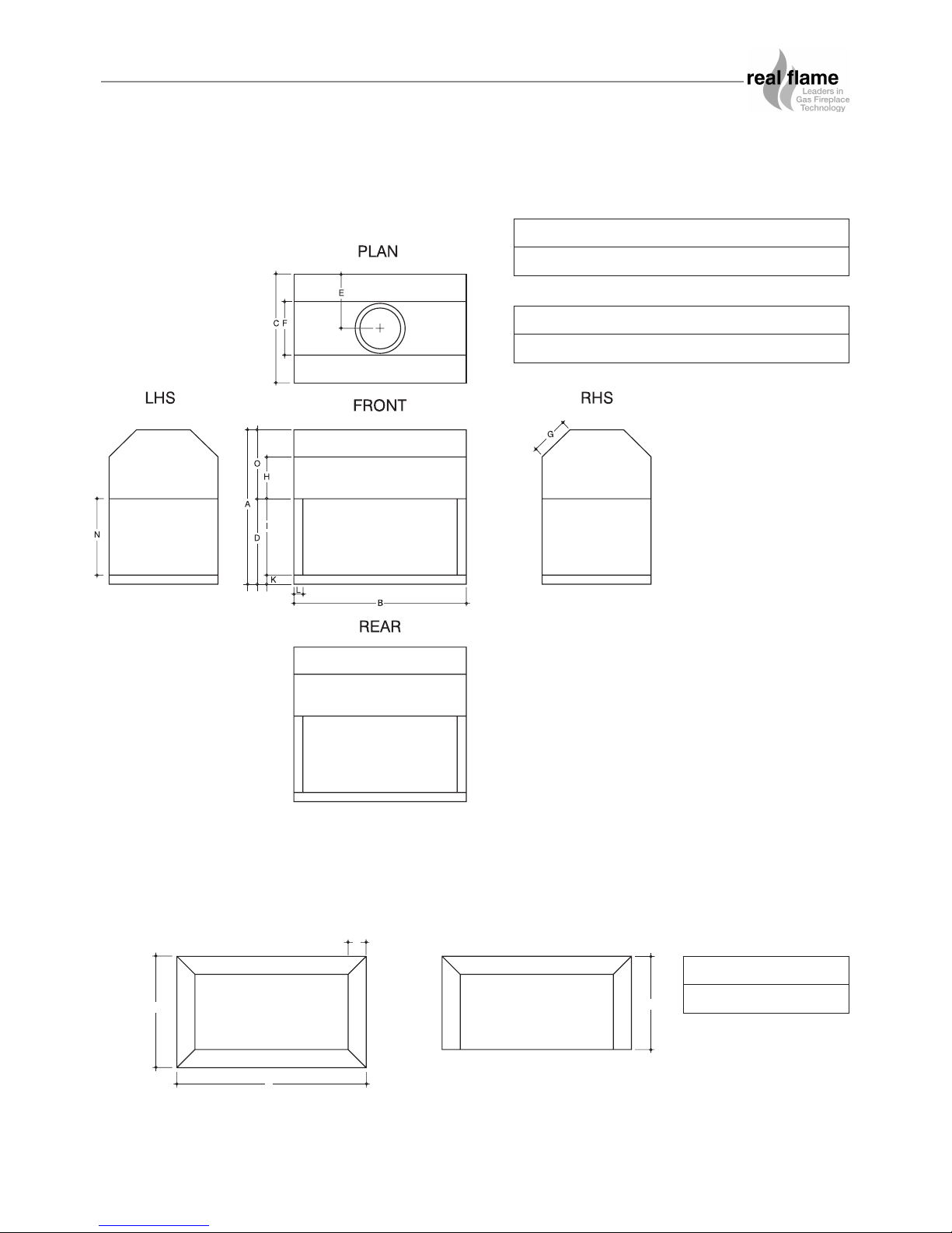
Overall Dimensions (in mm)
MODEL Inner Outer
850 225mm 275mm
6
FRONT - 4 SIDED FRONT - 3 SIDED
B
A
C
D
DIMENSIONS
Trim
AB CDEF GH
850 950 600 470 272.5 295 210 230
IJKLMNO
420 - 50 50 - 420 380
AB CD
1043 613 513 100
7
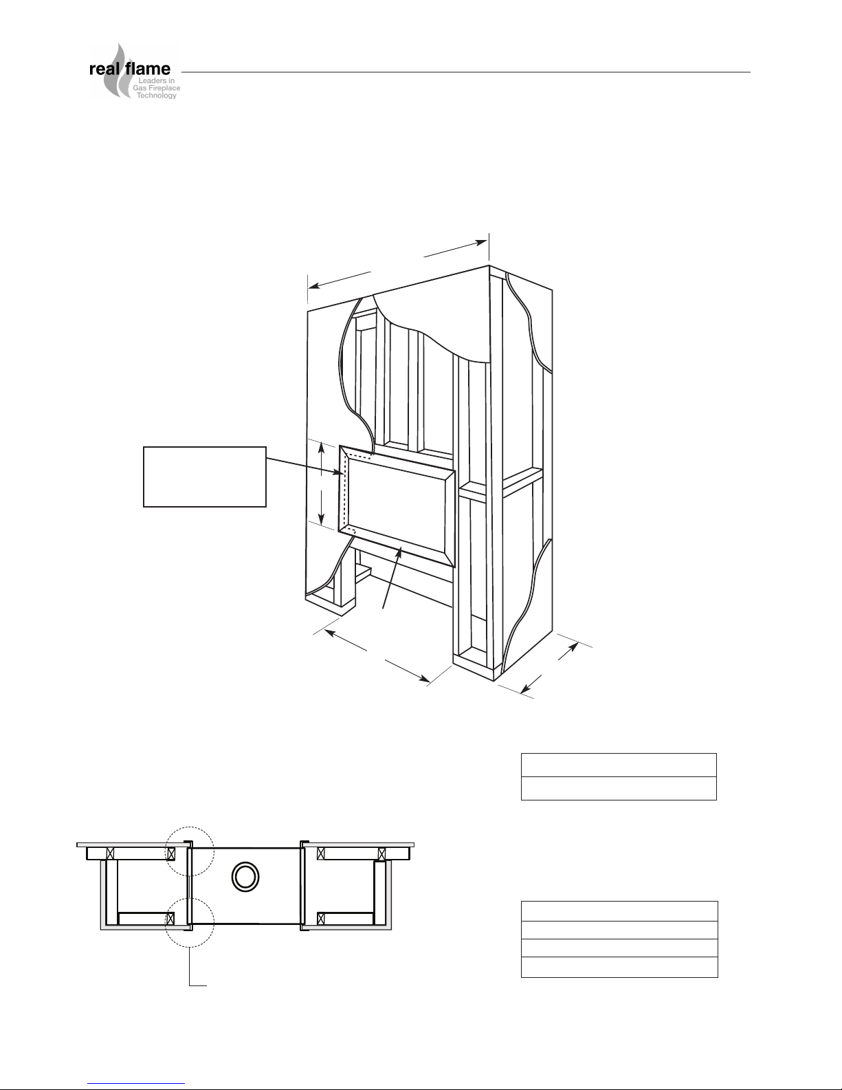
DOUBLE VISION FIREBOX
Double Vision Zero Clearance Timber Frame Installation
Floor 0 mm
Sides 25 mm
Top 100 mm
Flue Outer 25 mm
CLEARANCES FROM
COMBUSTIBLES
Plasterboard to run beyond stud as shown.
If unit requires trim only, frameout remains the same.
NOTE
PLAN
Plaster to run
beyond stud and
behind trim
A
B
C
D
(Recommended only)
HEATER
TRIM
AB C D
950 1000 600 2100
Frameout Dimensions (in mm)
8
Check frame out has been constructed correctly and has not been plastered.
Check frame out and structure above is clear of any structures that may impede the flue run.
TICK BOXES
DOUBLE VISION FIREBOX
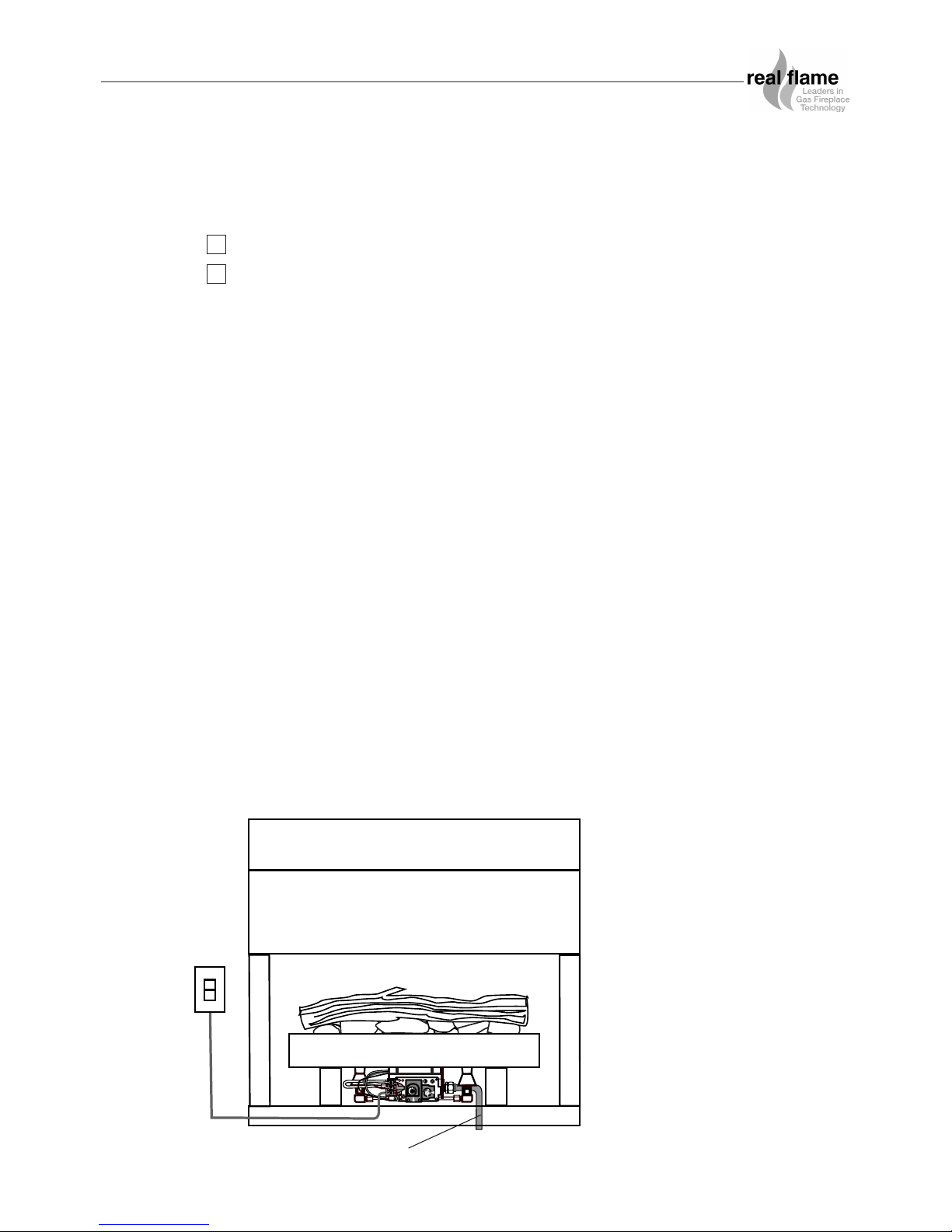
Double Vision Inbuilt Installation Procedure
• Ensure an adequately sized gas connection is available within the frame out, a 15mm gas
copper pipe is to be provided into the firebox. An access hole is provided in the base of the
firebox. A 500mm tail is required into the firebox to allow for connection to the burner.
• Position the unit ensuring the millivolt loom and gas pipe are accessible.
• Connect the twin skin flue (or Optional Power Flue if supplied).
• Install an AGA approved 225mm gas cowl ensuring the termination meets all relevant code
requirements.
• Place the burner in the double sided firebox.
• Connect the gas line to the burner connection using the 15mm flared copper union
(supplied).
• Connect the two core wiring terminals to the millivolt system as shown below.
Note: The valve is pre wired and completely self contained to generate its own power. DO
NOT connect any external power to it.
Note: Do not locate the switch further than 6 meters from the firebox.
• Screw the four burner legs to the base of the firebox in the holes provided.
• Place the burner surround over the burner.
• Place the coals (or optional pebbles) randomly on the ceramic blanket. If coals and logs
option is supplied, place logs on top of coals randomly.
IMPORTANT! Only ceramics supplied by Real Flame are to be used.
GAS LINE INLET
9
 Loading...