

RealFlame DiNatale 1330 Installation Instructions Manual
PO:____________
Lot:____________
50” DiNatale Wall-Mounted Fireplace
Model # 1330
English • Français • Español

TABLE OF CONTENTS
Parts List
Important Safety Instructions
Site Selection and Preparation
Installation
Operation and Features
Care and Maintenance
Warranty
2
3
5
6
12
15
16
PARTS LIST
Part Name Part No. Qty. Part Name Part No. Qty.
1 Remote control 13300001 1
2 Crushed glass 13300004 1 box (1.4 kg)
4 Mounting screws 12
(Note: Attached to the firebox)
5 Glass front panel 13300005 1
3 Mounting bracket 13300003 1
(Note: Attached to the firebox)
Hardware Kit - 13300002
A
B
C
x4
x4
x4
1
2
4
3
5
NOTE
Tools required: level, electric drill, drill bits [8mm (5/16in)], Phillips screwdriver,
hammer, safety goggles and gloves.
2

IMPORTANT SAFETY INSTRUCTIONS
SAVE THIS USER’S GUIDE FOR FUTURE REFERENCE
When using electrical appliances, basic precautions should always be followed to reduce the
risk of fire, electric shock, injury or death.
Read all instructions before installing or using this fireplace
1. Electric fireplace is for indoor use only.
2. Do not modify the electric heater in any way. Use it only as described in this manual.
Any other use not recommended by Real Flame may cause a fire, electric shock,
serious injury or death.
3. The heater may become hot when in use and could burn you. To avoid burns, do not
let bare skin touch hot surfaces. Keep combustible materials, such as furniture,
pillows, bedding, papers, clothes, and curtains at least 3 feet (0.9m) from the top,
sides and rear of the unit.
4. Always use properly grounded, fused and polarized outlets.
5. Always call a certified electrician if new circuits or outlets will be required.
6. Extreme caution is necessary when any heater is used by, or near, children or
people with disabilities. The unit should never be left unattended.
7. The electric heater is not intended for use in bathrooms, laundry areas and similar
indoor locations. Never locate heater where it may fall into a bathtub or in other areas
where it may come into contact with water; dangerous electric shock could occur.
8. Do not operate any unit with a damaged cord or plug, or if the heater has
malfunctioned, or if the fireplace has been dropped or damaged in any
manner. Contact Real Flame at 1-800-654-1704.
9. The cord may become hot when the fireplace is in operation. Do not run the cord
under carpeting, furniture, or appliances. Do not cover cord with throw rugs, runners,
or similar items.
10. To prevent people from tripping on the cord, make sure it is placed away from high
trac areas.
11. Do not insert or allow foreign objects to enter any ventilation or exhaust opening
as this may damage the heater or result in electric shock.
12. To prevent a possible fire, do not block air intake or exhaust in any manner. Do not
use on soft surfaces, like a bed, where openings may become blocked.
13. All electrical heaters have hot, arcing or sparking parts inside. Do not use in areas
where gasoline, paint, or flammable liquids are used or stored or where the unit will
be exposed to flammable vapors. Doing so could result in a fire or cause an explosion.
14. Do not burn wood or other materials in the electric heater; the unit or the wall could
catch fire if you do.
15. To disconnect the unit, turn the firebox o and then remove the plug from the
outlet.
16. Always unplug the electric heater when not in use for an extended period of time.
Glass Panel Information
1. The panel is made of tempered glass.
2. Under no circumstances should this product be operated with a broken or
chipped glass panel.
3. Do not hit or slam the glass.
4. Do not use abrasive cleaners to clean the glass.
3

IMPORTANT SAFETY INSTRUCTIONS (Cont’d.)
SAVE THESE INSTRUCTIONS
WARNING
!
!
•Risk of electric shock
•Do not open
•Non-user serviceable parts inside
DESCRIPTIONS OF WARNINGS
NOTE Procedures and techniques that are considered important
!
enough to emphasize.
CAUTION Procedures and techniques which, if not carefully followed,
!
will result in damage to the equipment.
WARNING Procedures and techniques which, if not carefully followed,
will expose the user to the risk of fire, serious injury, illness or
death.
NOTE This equipment has been tested and found to comply with the limits for Class
!
B digital device, pursuant to part 15 of the FCC Rules. These limits are designed
to provide reasonable protection against harmful interference in a residential
installation. This equipment generates, uses and can radiate radio frequency energy
and, if not installed and used in accordance with the instructions, may cause harmful
interference with radio or television reception. That can be determined by turning
the equipment o and on. The user is encouraged to try to correct the interference
by one or more of the following measures:
•Reorient or relocate the receiving antenna.
•Increase the separation between the equipment and the receiver.
•Connect the equipment into an outlet on a circuit dierent from that to which
the receiver is connected.
•Consult the dealer or an experienced radio / TV technician for help.
Operation is subject to the following two conditions:
(1) This device may not cause interference.
(2) This device must accept any interference, including interference that may
cause undesired operation of the device.
NOTE A 15amp, 120-volt circuit is required. A dedicated circuit is preferred but
!
not essential in all cases. A dedicated circuit will be required if, after installation,
the circuit breaker trips or the fuse blows on a regular basis when the heater is
operating. Additional appliances on the same circuit may exceed the current rating
of the circuit breaker.
If you have any questions about our products please contact Real
Flame® customer service at 1-800-654-1704
4

SITE SELECTION AND PREPARATION
WARNING
To reduce the risk of fire or electric shock when installing:
• Make sure the power cord is not pinched or against a sharp edge when installed.
• Ensure that the power cord is stored or secured to avoid tripping or snagging.
• Construction and electrical outlet wiring must comply with local building codes
and other applicable regulations.
• Do not attempt to wire your own new outlets or circuits. Always call a licensed
electrician.
COVER OF GROUNDED
See figure 1 for grounding instruction.
This heater is for use on 120 volts.
The cord has a plug as shown at A in
Figure 1. An adapter as shown at C is
available for connecting three-blade
grounding-type plugs to two-slot
receptacles. The green grounding lug
extending from the adapter must be
connected to a permanent ground
such as a properly grounded outlet
box. The adapter should not be used
if a three-slot grounded receptacle is
available.
GROUNDING PIN
GROUNDING
MEANS
*ADAPTER
NOTE: This adapter is
prohibited in Canada.
OUTLET BOX
METAL SCREW
NOTE: This adapter is
prohibited in Canada.
GROUNDING PIN
Fig. 1
5

INSTALLATION
WARNING This appliance is designed to be fixed to a wall at a minimum height of
12 in (300mm) and at a minimum distance of 39in (1000mm) from the top of the
heater to the ceiling. The wall bracket must be fitted horizontally with the cable
routed to the bottom right of the fireplace.
NOTE A distance of 23.62in (600mm) from the base of the fireplace to the floor is
recommended for the best view of the fireplace.
NOTE Two people are required for installation.
50” (1271 mm)
Floor
Step 1: Place the fireplace on a padded surface. Unscrew the 6
mounting screws on the top and 2 mounting screws on each side of
the fireplace (see Fig. A ). Set these screws to the side.
17.7” (450 mm)23.6” (600 mm)
Fig. A
6

INSTALLATION (Cont’d.)
Step 2: Remove the front glass as shown in Fig B. Handle it with care.
Fig. B
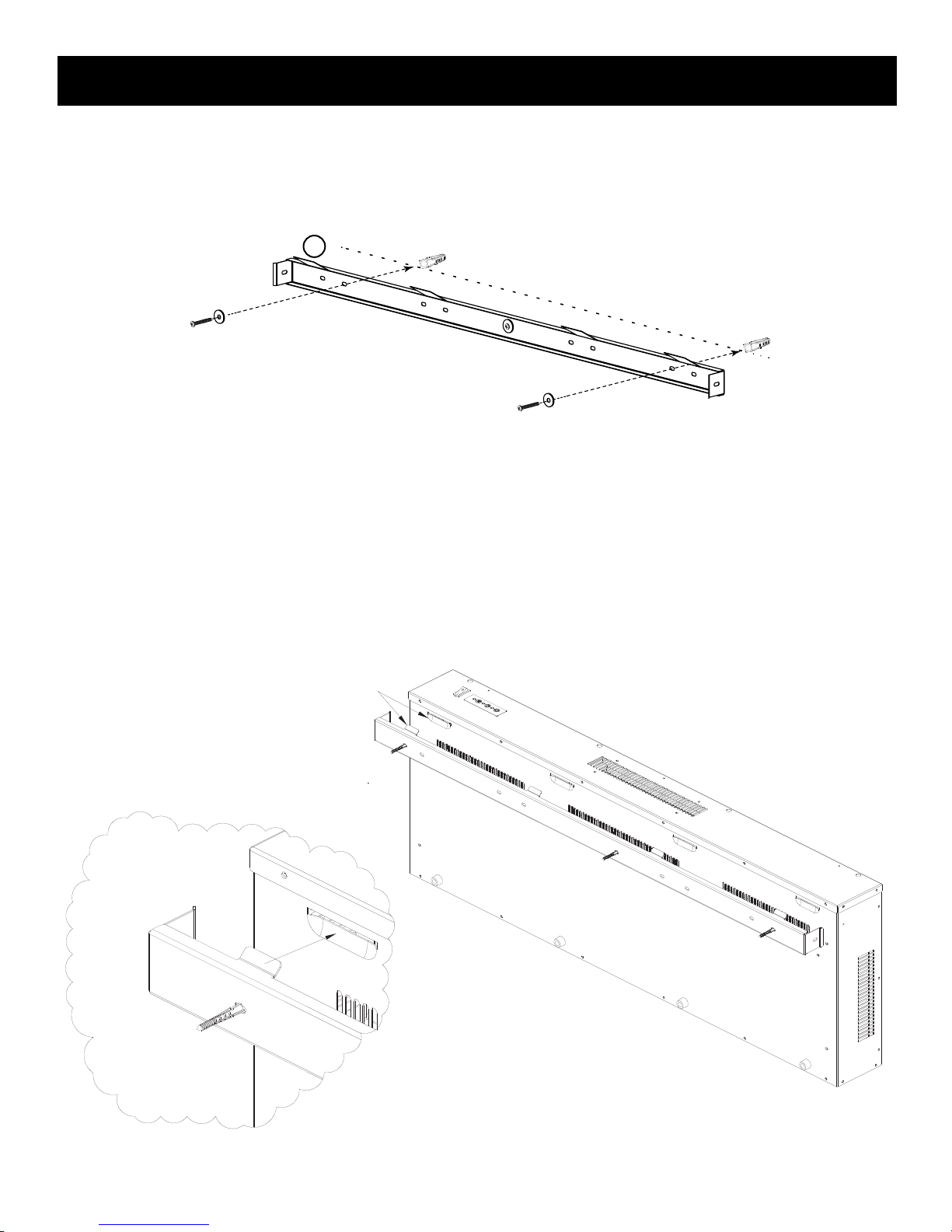
Step 3: The mounting bracket is fixed on the back of the fireplace.
Unscrew 2 screws and remove the bracket. See Fig. C.
Fig. C
7

INSTALLATION (Cont’d.)
Mounting the Firebox Bracket
Step 4:
• Locate studs where the firebox will be mounted.
• Following the height diagram on page 6, mark the location on a stud and drill a 1/16”
pilot hole for mounting the bracket to a wall stud. One stud is required to safely
mount this bracket using either of the holes in the center of the mounting
bracket (3).
• Attach the mounting bracket to the wall using one screw.
• Level the bracket and mark the remaining hole locations.
• Install remaining screws to finish mounting the bracket (3).
Wall stud
3
A
Step 5: For the holes that do not hit a stud, drill holes 5/16in(8mm) and use the supplied
wall anchors. Install the wall anchors into the holes and gently tap them into place with a
hammer until the flange of the wall anchor is flush with the wall surface. See Fig. E.
C
Drill 1/16” pilot hole
Install into wall stud
A
C
A
Fig. D
C
56 mm
B
B
Fig. E
8
INSTALLATION (Cont’d.)
Step 6: Secure the mounting bracket to the wall anchors using the anchors
and screws as shown in Fig. F.
3
A
C
A
C
Fig. F
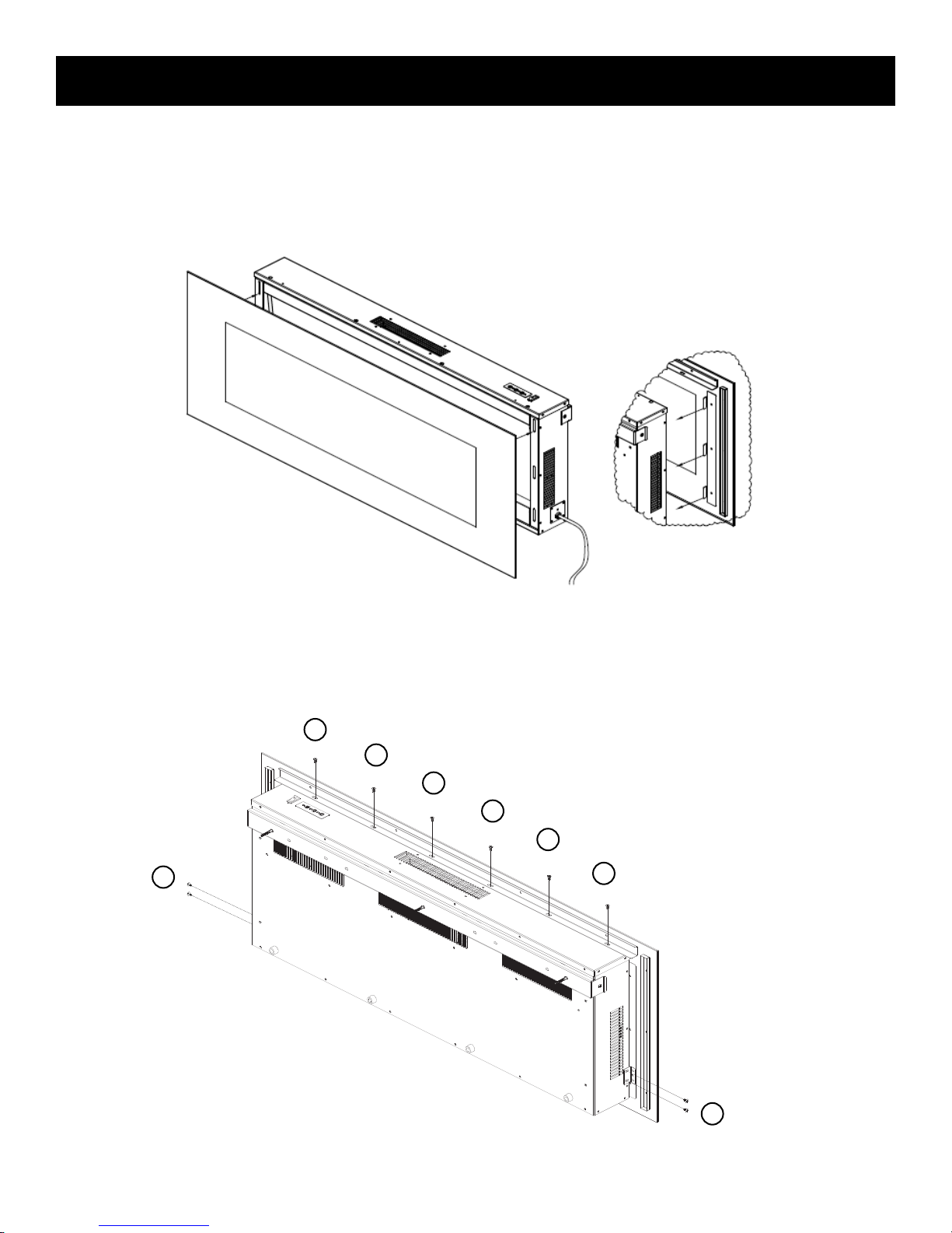
Step 7: Mount the fireplace on the wall using the slots of the metal bracket
at the back of the fireplace. See Fig. G. Make sure that the mounting
bracket is completely engaged into the metal bracket at the back of
the fireplace.
Fig. G
9

INSTALLATION (Cont’d.)
Step 8: Secure the mounting bracket to the fireplace using 2 mounting
screws. See Fig. H.
4
4
Fig. H
Step 9: Put the crushed glass onto the shelf panel of the fireplace.
See Fig. I.
2
Fig. I
10
INSTALLATION (Cont’d.)
Step 10: Hold the front cover tightly and engage it with the 6 slots
on both sides of the fireplace. Make sure the front cover has been
completely inserted into ALL 6 slots before removing your hands.
See Fig. J.
Fig. J
Step 11: Secure the front cover to the top and both sides of the
fireplace using 10 mounting screws. See Fig. K.
4
4
4
4
4
4
4
Fig. K
11
4
OPERATION AND FEATURES
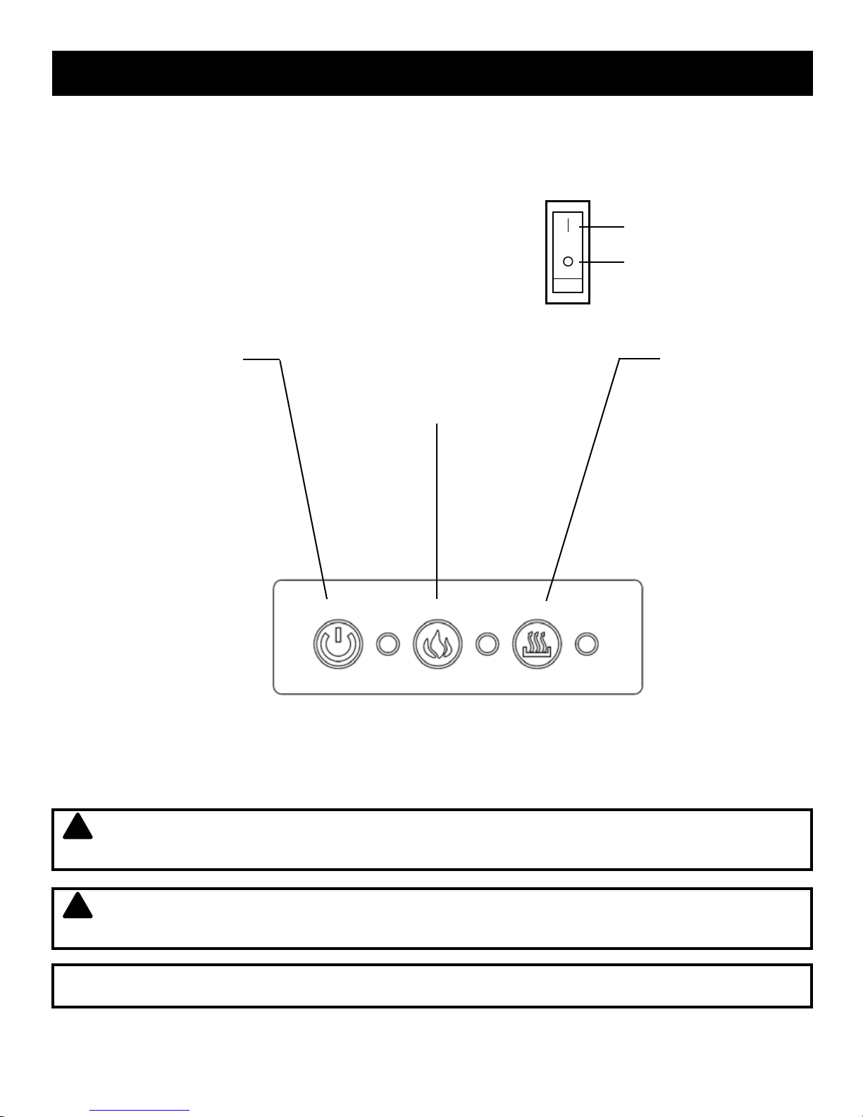
CONTROL PANEL OPERATION
After reading all the instructions, confirm that all controls on fireplace are in the OFF
position. Plug the fireplace into a 15AMP/120Volt outlet. The control panel is located at the
top right of your fireplace.
ON
MAIN POWER
Press the O/I button for main power.
POWER (Standby)
Push this button to turn
the unit on. Push it again
to enter stand-by mode.
FLAME COLOR
Changes the color of
the flame.
OFF
HEAT SETTING
Press this button
once for the low
heat setting (700W);
press twice for the
high heat setting
(1400W); press again
to turn o the heater.
Note: When the O/I switch is turned OFF, all other fireplace functions will stop.
NOTE When turned to standby the embers of the flame will not immediately go out.
!
This is a designed feature to represent the embers of the fire slowly fading out.
!
NOTE Although the heater has been turned o the fan may still run to prevent
over-heating.
TECHNICAL SPECIFICATION Supply: 120V~60Hz. Rated Power: 1400W
12

OPERATION AND FEATURES (Cont’d.)
REMOTE CONTROL OPERATION
To use the remote control, make sure that the Power Switch (I/O) on the fireplace has
been turned on.
POWER (STANDBY)
This will turn the unit ON/
OFF in standby mode.
FLAME COLOR
This button changes the
color of the flame.
ADJUST BRIGHTNESS
This allows you to raise or
lower the level of flame
brightness.
HEAT SETTING
Press this button once for
the low heat setting (700W);
press twice for the high heat
setting (1400W); press again
to turn o the heater.
REMOTE CONTROL BATTERY REPLACEMENT
The remote control requires one 3V CR2025 Lithium Cell Battery (included).
Remove the protective sheet between the battery and the contacts in order to
operate. See Fig. L.
Fig. L
13

OPERATION AND FEATURES (Cont’d.)
If the remote control stops operating or its range seems reduced, replace
the battery with a new one.
Replace with a CR2025 battery and follow the diagram at the back of
the remote handset to install the new battery. See Fig. M.
1. The battery compartment is located on the back end of the remote.
2. Press and slide the battery door open and remove the old battery.
3. Insert a CR2025 battery, checking that the “+” and “-” terminals of
the battery match the inside of the battery compartment.
4. Replace the battery compartment door.
Fig. M
14

CARE AND MAINTENANCE
C SU
WARNING
Disconnect power before attempting any maintenance or cleaning to reduce the risk of
fire, electric shock, injury or death.
CLEANING
Before cleaning the unit, first turn o the O/I switch and unplug the unit from the
power source.
• Dust the fireplace using a clean dry cloth.
• Use warm water and a clean cloth to wipe o any painted surfaces. Do not use abrasive
cleaners.
• Use a standard glass cleaner for the glass panel of the fireplace.
CAUTION
!
When transporting or storing the unit and cord, keep in a dry place free from excessive
vibration, and store carefully to avoid damage.
Light Emitting Diode
This firebox is fitted with LED (Light Emitting Diode) bulbs in place of conventional bulbs.
These generate the same light levels as conventional bulbs, but use a fraction of the
energy. These LED bulbs are maintenance free and should not require replacing during the
life of the product.
15
 Loading...