

Real Flame Captiva 600, Captiva 900 Installation & Operating Manual
CAPTIVA
®
BALANCED
FLUE SPACE HEATER
INSTALLATION & OPERATING MANUAL
The Captiva 600 & 900 are approved to be installed as a zero clearance
firebox and are designed to operate on Natural Gas and Propane (LPG)
gases ONLY. Approval Number GSCS20081.
VERSION 28

2
WARRANTY INFORMATION
The benefits provided to you under the following warranty are in addition to any other rights and remedies available to
you under the law.
1. Warranty
If:
(a) during the first 15 years from the date of purchase (Firebox Warranty Period), there is a defect in the firebox of the
Real Flame Gas Burner; or
(b) during the first 2 years from the date of purchase (Parts Warranty Period), there is a defect in the gas valves or
other parts of the Real Flame Gas Burner,
due to improper workmanship or material, Real Flame will replace or repair the Real Flame Gas Burner without
charge. Any replacement product is warranted only for the time remaining on the original Firebox Warranty
Period or the Parts Warranty Period as relevant.
2. Registration
You must register to receive the benefit of this warranty by completing the warranty registration on our website
(www.realflame.com.au) or completing and mailing the attached registration card within 30 days of purchase of
your Real Flame Gas Burner (or, if the Real Flame Gas Burner is fitted to a new home, within 30 days of the date
of settlement of purchase of such new home).
3. Exclusions
Real Flame is not obliged to replace or repair the Real Flame Gas Burner under clause 1 if:
(a) it has been improperly stored, installed, connected, used, operated or repaired, or damaged, abused, tampered
with, altered (without our written approval), or not maintained in strict accordance with our installation and
operating instructions; or
(b) it has been installed in an outdoor setting.
4. Limit of Liability
The warranty provided under this warranty is limited to replacement or repair of the Real Flame Gas Burner only,
at our option. To the extent permitted by law, Real Flame excludes liability for consequential loss or any other loss
or damage caused to property or persons arising from any cause whatsoever, and damage arising from normal
wear and tear.
5. Claiming under the Warranty
In order to claim under this warranty you must, within the Firebox Warranty Period or the Parts Warranty Period
(as relevant), contact Real Flame, providing the original proof of purchase and the details below:
Supplier Name___________________________________________________________________________
Date Of Purchase / settlement of property if new home _________________
Model / Serial Number_______________________
This warranty does not cover the cost of claiming under the warranty or transporting the Real Flame Gas Burner to and
from the supplier.
Our goods come with guarantees that cannot be excluded under the Australian Consumer Law. You are entitled to a
replacement or refund for a major failure and for compensation for any other reasonably foreseeable loss or damage.
You are also entitled to have the goods repaired or replaced if the goods fail to be of acceptable quality and the failure
does not amount to a major failure.
If you would like to speak to someone about your Real Flame Gas Burner or claiming under this warranty, please
contact the Real Flame Service Warranty Desk on 03 8706 2000.
Real Flame Pty Ltd ACN 006 311 155
Head Office: 1340 Ferntree Gully Road, Scoresby 3179
Telephone: 03 8706 2000 Facsimile: 03 8706 2001
WARNING
The “Captiva 600 & 900” have a primary safety glass fitted in front of the glass door. This safety glass is
fitted to these appliances to reduce the risk of injury from burns and at no time should this glass be
permanently removed.
For protection of young children or the infirm, a secondary guard is required.
INSTALLATION NOTICE
The installation of this appliance is only to be carried out by an authorised person in accordance
with the Manufacturer’s Instructions, local gas fitting regulations, AS5601-2004 installation code for
gas burning appliances and any other relevant statutory regulations.
In all cases the installation of this appliance shall meet the requirements as set out in AS5601-2004.
NOTE: A slight smell may be apparent for the first few hours of use. This is due to the heat resistant
paint curing. It is recommended to open windows in the room for the first lighting of the fire. In some
instances a slight discolouration may occur inside the firebox. This is a normal condition and is not
covered by warranty.
IMPORTANT SAFETY NOTICE
DO NOT PLACE ARTICLES ON OR AGAINST THIS APPLIANCE.
DO NOT USE OR STORE FLAMMABLE MATERIAL NEAR THE APPLIANCE.
DO NOT SPRAY AEROSOLS IN THE VICINITY OF THIS APPLIANCE WHILST IT IS IN OPERATION.
CARE MUST BE TAKEN TO ENSURE THAT ANY RETURN AIR REGISTER OR EXHAUST SYSTEM
DOES NOT ADVERSLEY AFFECT THE OPERATION OF THE APPLIANCE OR DRAUGHT OF
CHIMNEY OR FLUE.
WARNING
The outer glass panel gets extremely hot! Precaution should be taken and young children
supervised at all times when heater is operating.
3
SERVICING
It is recommended you service your gas fire every 2 years as a minimum.

CONTENTS
Contents ..................................................................................................................4
Data Plate.................................................................................................................5
Zero Clearance introduction ....................................................................................6
Installation Procedure ..............................................................................................7
Dimensions Captiva 600 ..........................................................................................9
Dimensions Captiva 900 ........................................................................................10
Timber frame installation........................................................................................11
Vertical venting installation.....................................................................................13
Tests to be carried out by installer .........................................................................14
Servicing and maintenance ...................................................................................14
Parts list ................................................................................................................16
Gas control assembly ............................................................................................16
Flue termination (cowls) regulations .....................................................................18
Remote control operating guide............................................................................19
Optional marble hearth and/or margin set ............................................................22
Optional mantelpiece.............................................................................................23
Electrical diagram ..................................................................................................24
Real Flame contact information .............................................................................28
4
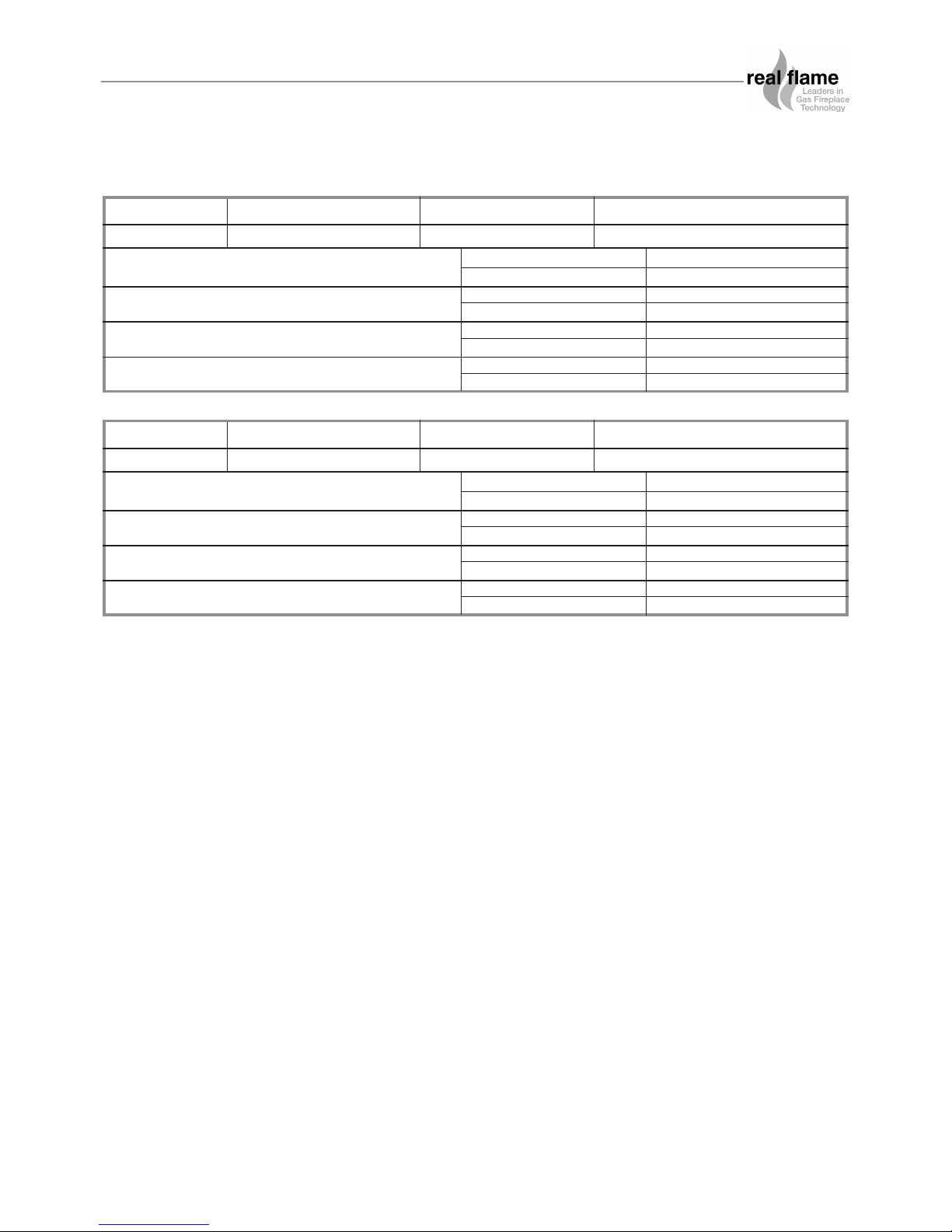
MODEL CAPTIVA 600 SERIAL NO. DATE OF MANUFACTURE
GAS TYPE APPROVAL: GSCS20081
NATURAL GAS @ 1.00 kPa Test Pressure Point (High) Injector Size Gas Consumption
1.65 mm 26 Mj/hr
LPG @ 2.65 kPa Test Pressure Point (High) Injector Size Gas Consumption
1.00 mm 26 Mj/hr
NATURAL GAS @ .40 kPa Test Pressure Point (Low) Injector Size Gas Consumption
1.65 mm 15 Mj/hr
LPG @ 0.95 kPa Test Pressure Point (Low) Injector Size Gas Consumption
1.00 mm 15 Mj/hr
MODEL CAPTIVA 900 SERIAL NO. DATE OF MANUFACTURE
GAS TYPE APPROVAL: GSCS20081
NATURAL GAS @ 1.00 kPa Test Pressure Point (High) Injector Size Gas Consumption
1.85 mm 30 Mj/hr
LPG @ 2.65 kPa Test Pressure Point (High) Injector Size Gas Consumption
1.1 mm 30 Mj/hr
NATURAL GAS @ .40 kPa Test Pressure Point (Low) Injector Size Gas Consumption
1.85 mm 19 Mj/hr
LPG @ 1.00 kPa Test Pressure Point (Low) Injector Size Gas Consumption
1.1 mm 18 Mj/hr
DATA PLATE (Affixed to the base of the unit for reference to gas pressure & consumption)
5

CAPTIVA ZERO CLEARANCE MODEL
INTRODUCTION
The Real Flame “Captiva” is a log/coal or pebble effect space heater for use with Natural Gas and
Propane.
The Real Flame warranty will be voided by, and Real Flame disclaims any responsibility for the
following actions:
• Modification of the space heater and/or components including balanced flue assembly or
glass door.
• Use of any component part not manufactured or approved by Real Flame in combination
with this “Captiva” fireplace system.
• Installation other than as instructed in this manual.
CAUTIONS
• Due to its high operating temperature, the appliance should be located out of traffic and
away from furniture and draperies.
• Children and adults should be alerted to the hazards of the high surface temperature, which
could cause burns of clothing ignition.
• Young children should be carefully supervised when they are in the same room as the
appliance.
• Clothing or other flammable materials should not be placed on or near the appliance.
SELECTING YOUR APPLIANCE LOCATION
Your appliance may be installed in any location that is free of air conditioning ducts, electrical
wiring and plumbing. Safety, as well as efficiency of operation, must be considered when
selecting the heater location. Try to select a location that does not interfere with room traffic, has
adequate ventilation, and offers access for the Balanced Flue terminal installation. Refer to
AS5601-2004 for minimum clearances for Balanced Flue termination.
WARNING
When this appliance is installed directly on carpeting, tile or other combustible materials other
than wood flooring, the appliance should be installed on a metal or wood panel extending the full
width and depth of the appliance.
6
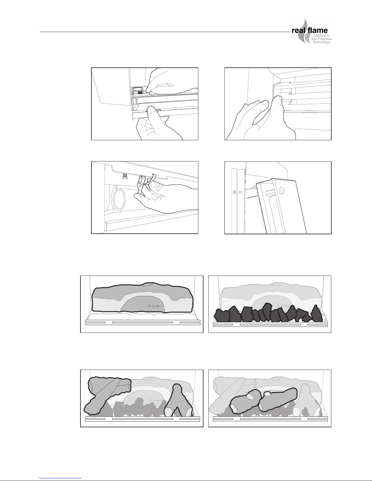
Figure (1) Remove bottom louvre door by
releasing spring loaded catch on left side.
Figure (3) Undo the door locating clips on
each side of the door.
Re-installation of glass door is reverse of above.
N.B. Ensure sealing rope is sitting securely in track prior to fitting door.
Figure (2) Remove top louvres by removing
the screws on each side.
Figure (4) Pull door outwards at the bottom
and then lift the door up and remove from
channel.
7
CAPTIVA INSTALLATION PROCEDURE
Figure (5) Remove box containing logset, and
unpack. Place the large log at the
rear of the firebox between the 2
location tabs.
Figure (6) Place the coals on top of the white
ceramic blanket.
Ensure front row of coals are placed
10 - 12mm away from the front grille.
Figure (8) Place the 2 straight logs as shown
Figure (7) Place the 2 ‘Y’ shaped logs as
shown, the larger on the left. Position
the ‘Y’ end of the logs towards the
front of the heater. N.B. 600 model
has only 1 ‘Y’ shaped log.
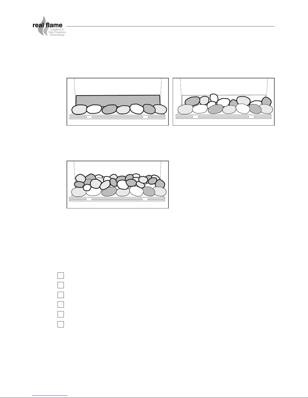
Figure (9) Install the metal angle at the rear of
the fireplace and place one row of
pebbles behind the burner rail.
Figure (10) Place pebbles between the first row
and the angled tray.
To install pebbles follow the installation instructions as per figures 1 to 4 above, and then proceed
as follows (figures 9 to 11)
Figure (11) Place remaining pebbles up the
angle of the rear tray so as the tray
is hidden.
Note: Keep pebbles clear of burner rail.
8
CAPTIVA INSTALLATION PROCEDURE
Note: If a coals only configuration is being used, use the same set up as pebbles.
Replace the glass front to its original position.
Fit the trim to the front of the heater.
Light the unit following the procedure on pages 19-21.
Test the unit for safe operation and show customer correct operating procedures.
Test for spillage.
Perform pressure test.
TICK BOXES
B
C
D
E
F
G
H
I
J
K
L
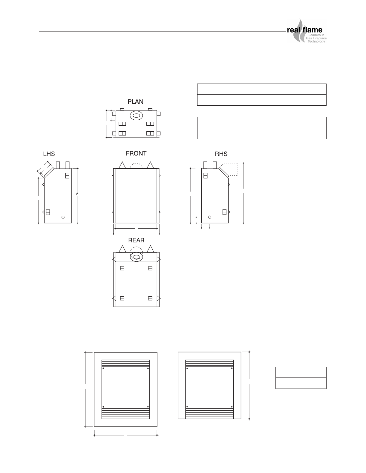
FRONT - 4 SIDED FRONT - 3 SIDED
B
A
C
DIMENSIONS
Captiva 600
AB CDEF GH
782 780 588 655 860 645 190 180
IJKL
385 140 85 120
Captiva 600 Trim
AB C
790 930 840
9
 Loading...