

Real Flame CALDOR Installation & Operating Manual
CALDOR WOODHEATER
C
INSTALLATION & OPERATING MANUAL
VERSION 2

FOREWARD
THANK YOU FOR CHOOSING THIS WOOD INBUILT
We want to congratulate you on your purchase and wish to help you get maximum satisfaction
f
technical specifications regarding installation, operation and maintenance of the model you have
c
The instructions pertaining to the installation of your wood inbuilt comply with AS/NZS 4012/4013
and AS/NZS 2918 standards.
Please read this entire manual before you install and use your new wood inbuilt. Failure to follow
instructions may result in property damage, bodily injury, or even death . It is important that you
follow the installation guidelines exactly.
Consult your local city, borough or shire council about restrictions and installations requirements in
your area and the need to obtain a permit.
This heating unit is designed to serve as a supplementary heat source. We recommend that a
primary heat source also be available in the home. The manufacturer cannot be responsible for
costs associated with the use of another heating system.
KEEP THIS MANUAL FOR FUTURE REFERENCE.
PLEASE NOTE THAT THE PICTURES SHOWN IN THIS MANUAL ARE GENERIC AND MAY
NOT MATCH EXACTLY THE LOOK OF YOUR ZERO CLEARANCE WOOD INBUILT.
rom your wood inbuilt. In the pages that follow, we will give you advice on wood heating as well as
hosen.
2

CONTENTS
INSTALLATION.......................................................................................................4
Safety Information ...................................................................................4
Regulations Covering Zero Clearance Wood Inbuilt Installation .............5
General Information.................................................................................6
Dimensions..............................................................................................6
Standoff Installation...............................................................................10
Carrying the Zero Clearance Wood Inbuilt ............................................10
Locating the Caldor ...............................................................................10
Clearances to Heat-Sensitive Materials.................................................11
Hearth Extension Construction Configuration .......................................13
Floor Protection .....................................................................................14
Compliance of a Combustible Mantel and Mantel Shelf........................15
Trim Installation .....................................................................................15
Moulded Refractory Brick Panels Installation........................................16
Hot Air Gravity System ..........................................................................17
THE FLUE SYSTEM.............................................................................................24
General..................................................................................................24
Minimum Flue System Height................................................................24
Suitable Flue Systems...........................................................................25
The Relationship Between the Flue System and the House .................25
OPERATION AND MAINTENANCE .....................................................................25
Safety Information .................................................................................25
Fuel........................................................................................................27
Operating Your Zero Clearance Wood Inbuilt........................................27
Maintaining Your Wood Heating System ...............................................29
Flue and Flue Liner Maintenance..........................................................32
EXPLODED DIAGRAM AND PARTS LIST...........................................................33
Real Flame contact information ............................................................................36
3

INSTALLATION
Install the zero clearance wood inbuilt only as described in these instructions and using only
components from the list below.
Parts Required
• BF16 zero clearance wood inbuilt;
• Flue:
- Flue lengths,
- Elbows (where necessary),
- Associated components as per these installation instructions.
Required Component (sold separately)
• Moulded bricks (SFA0080);
• Black straight narrow trim (SFA0085);
or
• Black straight masonry trim (SFA0087).
Options (sold separately)
• Air diffuser kit (SFA0086).
Safety Information
WARNING
• THE APPLIANCE AND FLUE-SYSTEM SHALL BE INSTALLED IN ACCORDANCE
WITH AS/NZS 2918 AND THE APPROPRIATE REQUIREMENTS OF THE RELEVANT
BUILDING CODE OR CODES.
• APPLIANCES INSTALLED IN ACCORDANCE WITH THIS STANDARD SHALL
COMPLY WITH THE REQUIREMENTS OF AS/NS 4013 WHERE REQUIRED BY THE
REGULATORY AUTHORITY, I.E. THE APPLIANCE SHALL BE IDENTIFIABLE BY A
COMPLIANCE PLATE WITH THE MARKING 'TESTED TO AS/NZS 4013'.
• ANY MODIFICATION OF THE APPLIANCE THAT HAS NOT BEEN APPROVED IN
WRITING BY THE TESTING AUTHORITY IS CONSIDERED AS BREACHING AS/NZS
4013.
CAUTION
• MIXING OF APPLIANCE OR FLUE SYSTEM COMPONENTS FROM DIFFERENT
SOURCES OR MODIFYING THE DIMENSIONAL SPECIFICATION OF
COMPONENTS MAY RESULT IN HAZARDOUS CONDITIONS. WHERE SUCH
ACTION IS CONSIDERED, THE MANUFACTURER SHOULD BE CONSULTED IN
THE FIRST INSTANCE.
• CRACKED AND BROKEN COMPONENTS e.g. GLASS PANELS OR CERAMIC TILES,
MAY RENDER THE INSTALLATION UNSAFE.
• A CARBON MONOXIDE (CO) DETECTOR/ALARM IS REQUIRED IN THE ROOM IN
WHICH THE ZERO CLEARANCE WOOD INBUILT IS INSTALLED. THE CO
DETECTOR WILL PROVIDE WARNING IF, FOR ANY REASON, THE APPLIANCE
FAILS TO FUNCTION CORRECTLY.
4

INSTALLATION (Continued)
NOTICE
• The information given on the certification label, affixed to the appliance, always
overrides the information published in any other media (owner’s manual, catalogues,
flyers, magazines or web sites).
• Connect this wood inbuilt only to a triple skin flue system as per AS/NZS 2918,
APPENDIX B, or any flue system tested to and past the requirements of AS/NZS 2918,
APPENDIX F, for use with solid fuel.
• If required, a supply of combustion air shall be provided to the room.
• Do not connect to, or use in conjunction with any existing air distribution ductwork
unless specifically approved with the appliance.
• Do not connect this unit to a flue serving another appliance.
• This zero clearance wood inbuilt has not been tested to be installed inside a masonry
chimney.
Regulations Covering Zero Clearance Wood Inbuilt Installation
When installed and operated as described in these instructions, the Caldor zero clearance wood
inbuilt is suitable for use in residential installations. The Caldor zero clearance wood inbuilt is not
intended for installation in a bedroom.
The zero clearance wood inbuilt is not approved for use with a so-called “positive flue connection”
to the clay tile of a masonry flue system.
CAUTION
• THIS CALDOR ZERO CLEARANCE WOOD INBUILT SHOULD BE INSTALLED ONLY
BY A LICENSED ACCREDITED INSTALLER. FAILURE TO USE AN AUTHORIZED
INSTALLER MAY VOID YOUR HOME & CONTENTS INSURANCE POLICIES.
PLEASE REFER TO YOUR RETAILER TO LOCATE AN INSTALLER.
5
INSTALLATION (Continued)
General Information
Model # SF00400
Colour Metallic black
Combustible Hardwood
Recommended heating area* < 93 m
Test Standards (safety) AS/NZS 2918
Test Standard (emissions) AS/NZS 4012 & 4013 (exempt**)
Flue Spigot Diameter 200 mm
Flue system Triple skin flue system
Ceramic glass thickness 4 mm
Maximum Log Length 760 mm
Firebox Volume 0,181 m
Shipping Weight 347 kg
* Heating capacity may vary subject to location in home, flue system draft, flue system diameter,
locality, heat loss factors, climate, fuels and other variables.
** This unit is tested as a central system because it can be hooked-up to hot air distribution ducts.
It is therefore exempt from emissions testing.
2
3
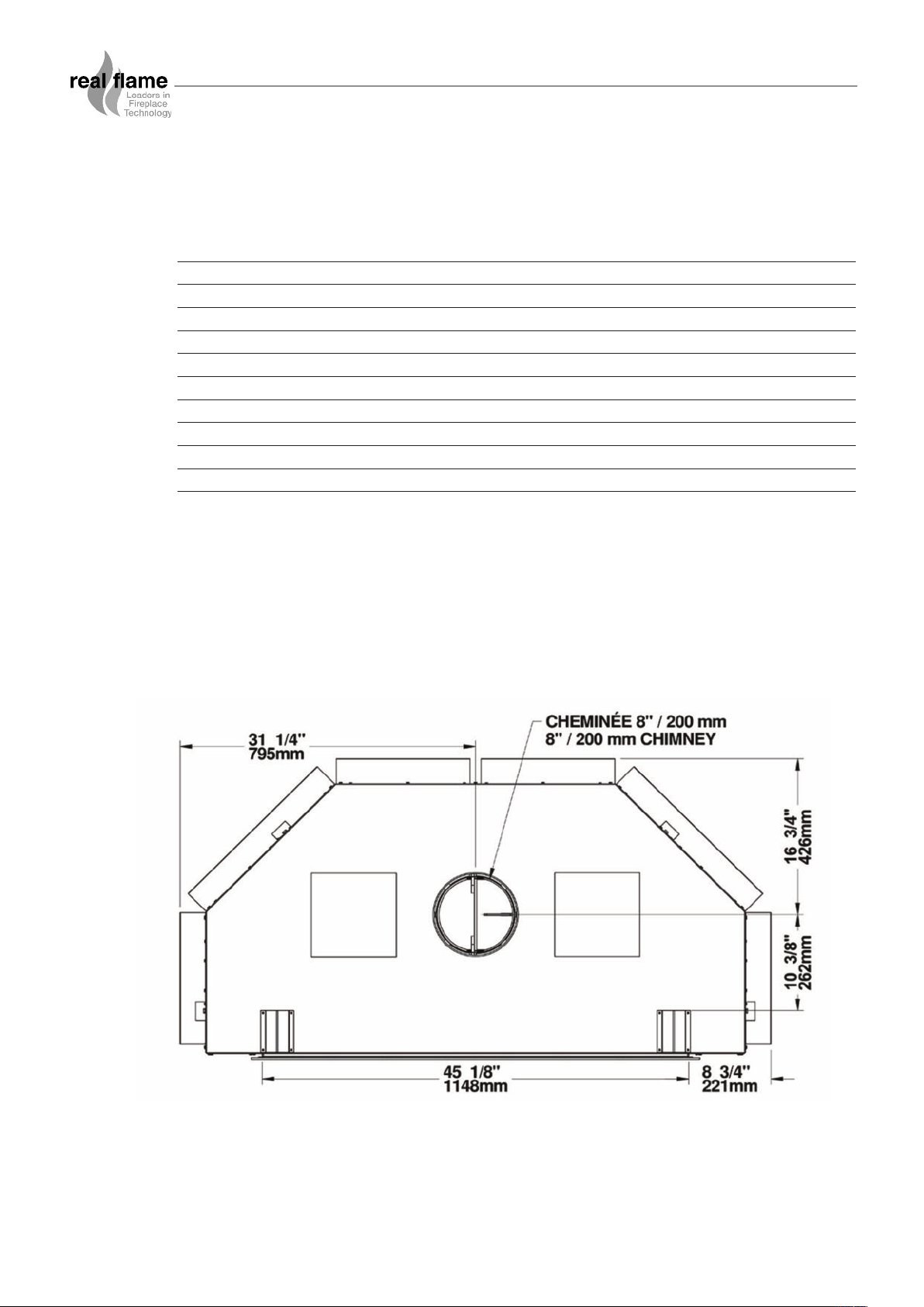
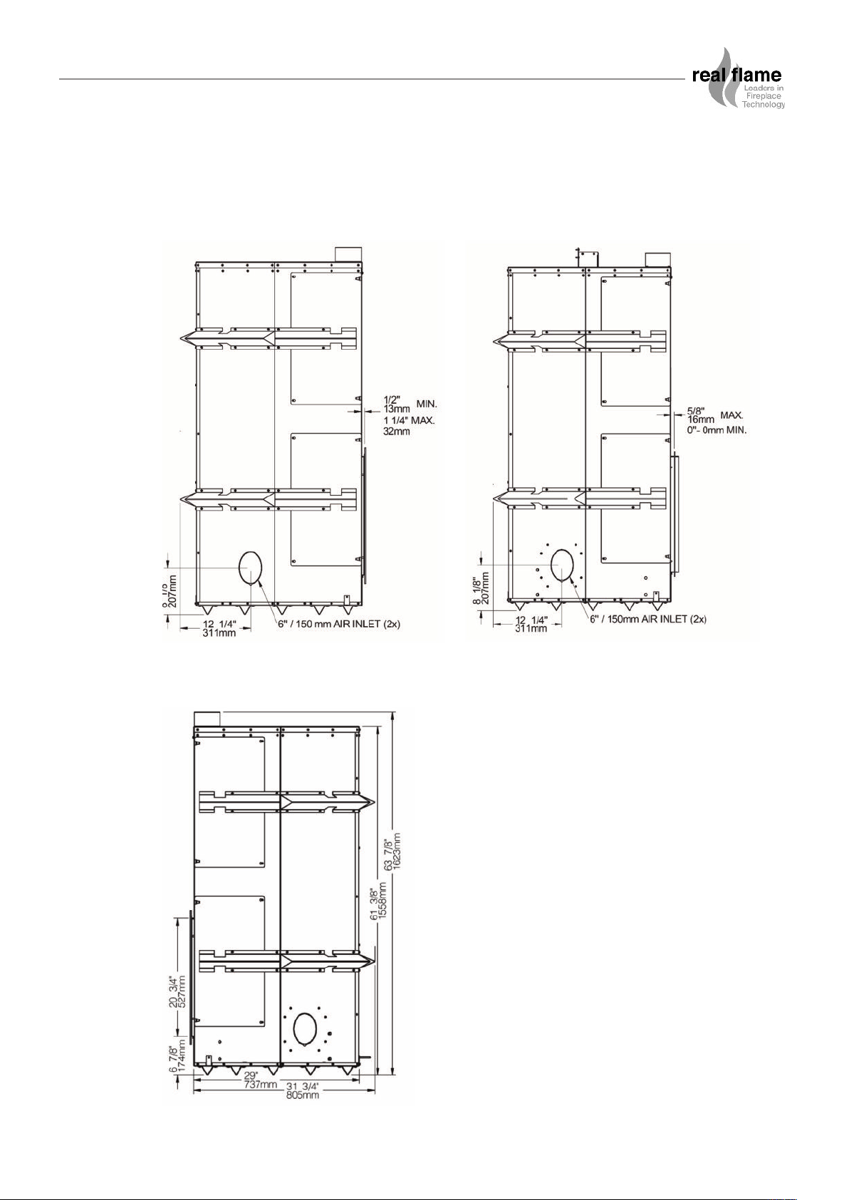
Dimensions
Top view
6
INSTALLATION (Continued)
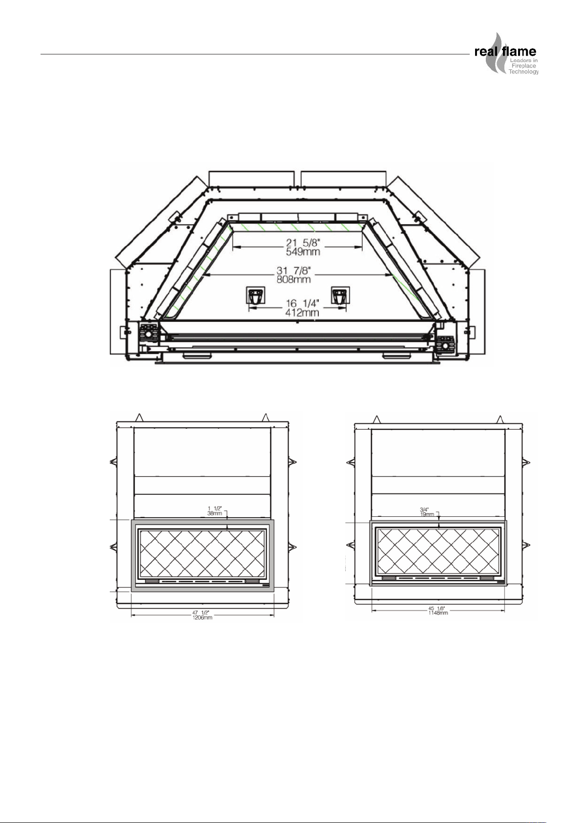
Dimensions (continued)
Combustion chamber
Black straight narrow trim Black straight masonry trim
7
INSTALLATION (Continued)
Dimensions (continued)
Glass surface
Door opening black straight narrow trim Door opening black straight masonry trim
Combustion chamber
8
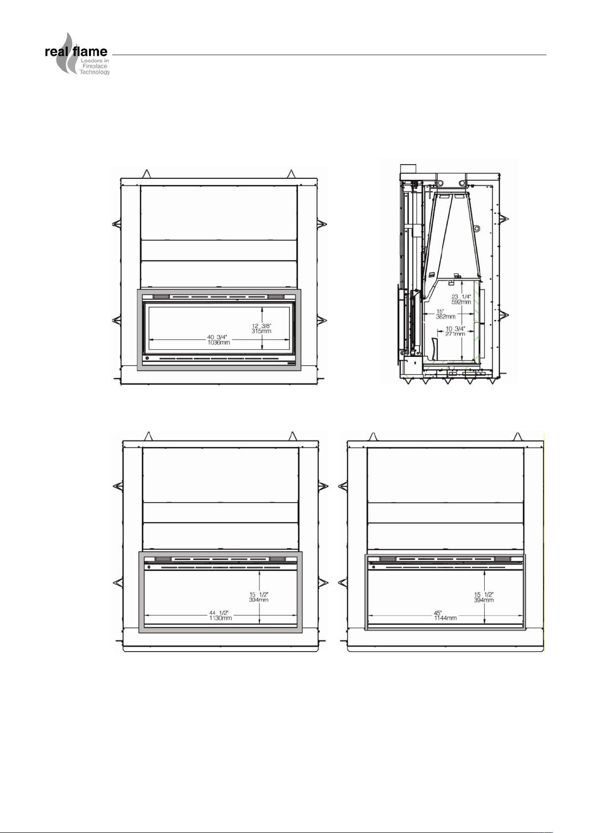
INSTALLATION (Continued)
Dimensions (continued)
Left side black straight narrow trim
Left side black straight masonry trim
Right side
9

INSTALLATION (Continued)
Standoff Installation
Before installing the zero clearance wood inbuilt, two standoffs must be secured to the top of the
ppliance. These parts are required to maintain proper clearances to heat sensitive materials. You
a
will find the standoffs in the firebox and the screws in the owner’s manual kit. Align the holes of the
spacers (A) with the pre-drilled holes on top of the zero clearance wood inbuilt and secure them
with 8 screws provided (B), as shown.
Carrying the Zero Clearance Wood Inbuilt
To facilitate transportation of the Caldor before its installation, we have designed handling grips
(AC09200, sold separately). The moulded bricks are in a box you can carry separately. We
suggest you install the bricks after the setting up of the zero clearance wood inbuilt. To install the
bricks, see section Moulded Refractory Brick Panels Installation.
Locating the Caldor
ng the
deri
i
ons
e s
c
n front of the uni
e i
pac
t
ned by
nbui
. Fi
gure s
c
fl
ow i
e wood i
n the room
The bes
oc
l
for the hearth extension and the mantel and clearances to other combustible materials. If possible,
choose a location wher
pipes or
str
Usually, no additional floor
the floor
are given in the section Gener
clear
deter
THE
STRAIGHT (NOT UNEVEN) SURFACE.
t l
, doors
on of wi
ati
ucture.
ance wood inbuilt. Note the floor construction and consult your local building code to
m
ZERO CLE
ndows
ical wir
electr
lso choose a location that allows installing the least number of offsets in the flue.
A
can be checked by fir
ine if additional suppor
ARANCE
and the traffi
e the vent will not interfere with any truss, roof beams, wall studs, water
ing. It m
ay be easier to relocate the appliance than to rework the building
support is needed for the zero clearance wood inbuilt. The adequacy of
st estimating the weight of the zero clearance wood inbuilt. Weights
al Information. Next, measure the area occupied by the zero
t is needed.
WOOD INBUILT MUST BE INSTALLED ON A LEVEL AND
earanc
l
ero c
our z
y
l
tal
ns
on to i
ati
oc
determ
s
t i
l
i
om
10
INSTALLATION (Continued)
Location of the Certification Label
Since the information given on the certification label affixed to the appliance always overrides the
nformation published in any other media (owner’s manual, catalogues, flyers, magazines or web
i
sites) it is important to refer to it to have a safe and compliant installation. In addition, you will find
information about your zero clearance wood inbuilt (model, serial number, etc.). You can find the
certification label inside the wood inbuilt, on the right side when facing it.
We recommend that you note the wood inbuilt’s serial number on this manual, since it will be
needed to precisely identify the version of the appliance in the event you require replacement parts
or technical assistance.
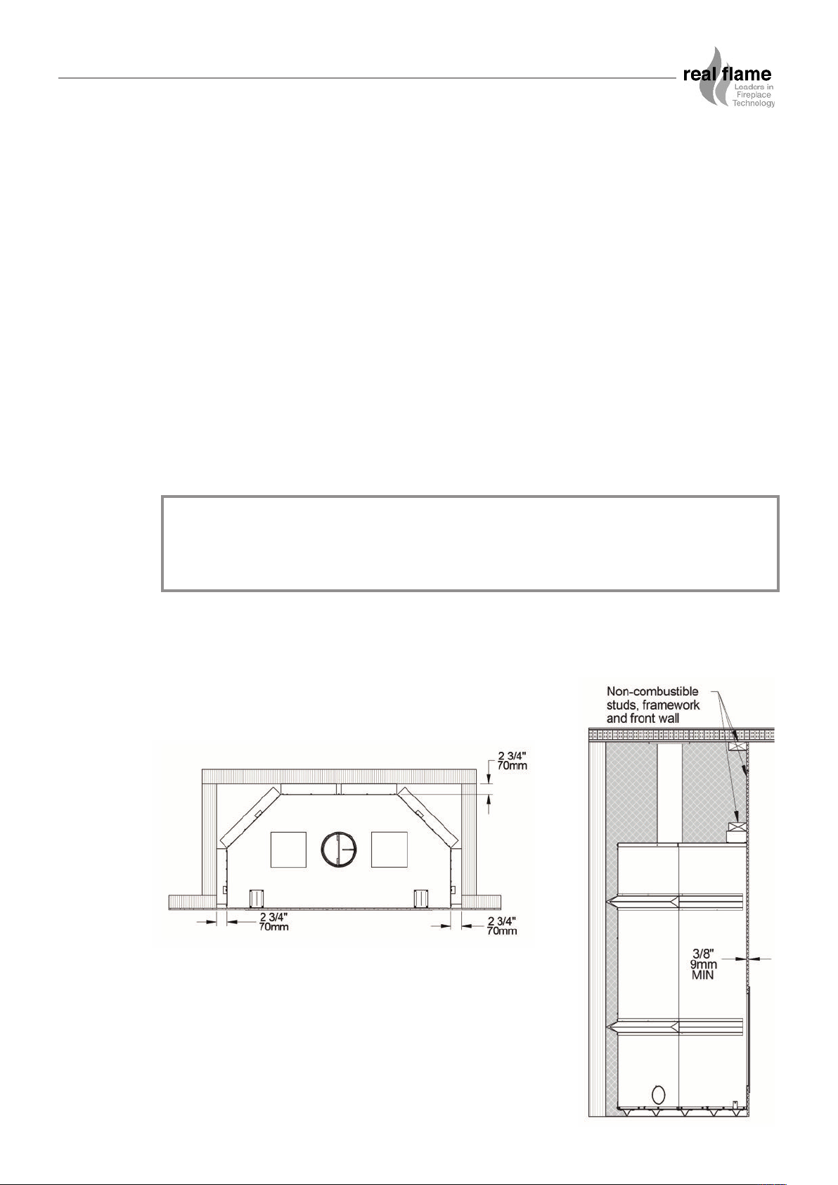
Clearances to Heat-Sensitive Materials
The clearances shown in this section have been determined by test according to procedures set
out in safety standards AS/NZS 2918:2001. When the zero clearance wood inbuilt is installed so
that its surfaces are at or beyond the minimum clearances specified, combustible surfaces will not
overheat under normal and even abnormal operating conditions.
WARNING
• NO PART OF THE ZERO CLEARANCE WOOD INBUILT MAY BE LOCATED CLOSER
TO COMBUSTIBLES THAN THE MINIMUM CLEARANCE FIGURES GIVEN.
The appliance must be built into an enclosure with the front wall made from a minimum 9 mm noncombustible material (Bellis board or similar), the side and rear walls, which can be made from
combustible material, shall be a minimum of 70 mm from the side and rear of the appliance outer
case.
11
 Loading...