

Page 1

Page 2

Forge/CTRL User Manual
P/N R-400015
Version 2.0
Welcome
You’re READY to unleash the power of industrial automation! The Forge/CTRL system is the future of easy-toprogram manufacturing automation. With this system, your business has the tools to enter a world of more
efficient and more precise manufacturing processes. This user manual, along with the included “Quick Reference
Guide” and “Risk Assessment Procedure,” will get you on the path to setting up your Forge/CTRL as soon as
possible.
Safety and risk assessment
The Forge/CTRL system is partly completed machinery and as such a risk assessment is required for each
installation of the system. It is particularly important that all relevant safety standards be observed. The system
itself is considered party completed machinery as the safety of the Forge/CTRL installation depends on how the
system is integrated (e.g. tool, obstacles, and other machines). A comprehensive risk assessment is often required
to comply with local and national safety standards and is always recommended. It is also recommended you follow
the guidelines in ISO 12100 and ISO 10218-2 to conduct the risk assessment.
Industrial robots can cause severe and fatal injuries to workers during interventions such as maintenance,
unjamming, adjustments, and setup.
The information contained herein is the property of READY Robotics Corporation and shall not be reproduced in
whole or in part without prior written approval of READY Robotics Corporation. The information herein is subject
to change without notice and should not be construed as commitment by READY Robotics. This manual is
periodically reviewed and revised.
Any information given in this manual regarding safety must not be construed as a warranty by READY Robotics that
the Forge/CTRL system will not cause injury or damage even if all safety instructions are complied with.
READY Robotics assumes no responsibility for any errors or omissions in this document.
Page 3

Forge/CTRL User Manual
P/N R-400015
Version 2.0
Safety and Precautions
4
Overview
General safety
Robot safety
Electrical safety
Pneumatic safety
Introduction to the Forge/CTRL
8
Overview
Choosing the right task
Overview of your system
TeachMate
Primary axes
Hardware Set Up
14
Overview
Connecting power and air
Starting the Forge/CTRL system
Attaching an end effector to the robot arm
Attaching devices to the air and PLC modules
Connect to a camera
103
Overview
Before you Begin
Setup the Camera
Setup the Camera in Forge/OS
Use the camera in a task
Troubleshooting and Technical Support
111
Technical Specifications
107
System technical specifications
Force sensor threshold values
Table of Contents
Page 4

Forge/CTRL User Manual
Safety and Precautions
Version 2.0
!
Be sure to follow all the safety rules and regulations of your workplace while using the Forge/CTRL
safety.
Safety and Precautions
Overview
The Forge/CTRL system connects to a variety of robotic arms and devices. Although some robot arms are
collaborative and designed to be used in proximity to people, there are still safety considerations that come with
working with any system that uses electric and air power for high-speed handling of parts.
General safety
system. None of the safety features built in to the Forge/CTRL overrule your workplace’s standards for
• Always wear all recommended personal protective equipment in accordance with your workplace’s safety
standards, including:
o Safety glasses
o Hearing protection
o Hard hats
o Steel-toe boots
o Chemical protective material
• Always use proper safety precautions when working with tools that contain sharp edges, pinching
surfaces, or generate heat.
• Always lift heavy objects with your legs, not your back. If you cannot lift an object alone, ask for help or
find another method to move it.
• Always store sharp objects, including robot tools and peripherals, in a safe location with sharp edges
covered.
• Always inspect all electrical and pneumatic cables to ensure that they are in good condition.
• Never allow minors to operate the Forge/CTRL system.
• Never enter the workspace of the robot while it is in motion or executing a task.
• Never use defective, dull, or broken tools.
• Never use the Forge/CTRL in an environment over 122º F (50º C).
• Never open the enclosure of the Forge/CTRL or attempt maintenance on the system’s internal
components.
Page 5

Forge/CTRL User Manual
Safety and Precautions
Version 2.0
Although safety devices and collaborative robot arms increase the safety of the work environment, it
A risk assessment must be performed for all collaborative applications.
Robot safety
does not mean that all devices used with the Forge/CTRL system or functions the system performs are
inherently safe as well.
!
• Always use caution around fast-moving objects, heavy objects, and sharp edges.
•
The Forge/CTRL system is designed to connect to a variety of robot arms. Some robot arms are human-safe and
designed to enter a protective stop when they contact any object, including a person. Whether the arm is
collaborative or not, there are some guidelines that should be considered when working with a robot arm.
• Know the motion limitations of your system and be sure to remove any objects that could be easily
damaged or destroyed from the reach of the arm. See your robot arm’s manual for specific details.
• The safest way to stop the robot arm is with either of the emergency stop buttons located on either the
monitor or the teach pendant.
• The main power switch is not an emergency stop switch. Do not use the main power switch for
emergency situations.
• Do not wear loose fitting clothing that could get stuck in a moving robot joint, end effector, or devices.
For safety information specific to the Universal Robots arm, see the included manual for the robot arm.
Collaborative robot arms
Forge/CTRL systems that include a human-safe, collaborative robot arm are designed to enter a protective stop
when they contact any object in their path, including a person. The force threshold for each robot arm varies,
consult your robot arm’s manual for specific information. When the force threshold is met the robot arm enters a
protective stop. Although this meets the threshold for a “human-safe” system, the robot arm can still cause injury
if carrying a sharp object or moving above shoulder height.
Safety modes
Depending on your set up, there are different safety modes you may experience during operation. The most
common safety mode is an emergency stop. If you are using a collaborative arm, the robot arm may enter a
protective stop. Reduced mode and safeguard stop are safety modes triggered by attached safety devices.
Page 6

Forge/CTRL User Manual
Safety and Precautions
Version 2.0
Safety modes - continued
Emergency stop
The robot arm enters an emergency stop when either an emergency stop button is pressed or when a high-speed
collision occurs. When in an emergency stop:
• The robot arm applies internal brakes to ensure rigidity.
• Attached end effectors and devices release grip and turn off.
• The TeachMate LEDs turn red.
• Forge/OS notifies you the robot is in an emergency stop and the margins are red and display “Robot
Error.”
If an emergency stop occurs because of an emergency stop button, Forge/OS instructs you to turn the emergency
stop button clockwise, releasing the stop. Once the stop is released, the robot arm enters idle mode.
If an emergency stop occurs because of a high-speed collision, Forge/OS instructs you to clear the system through
the teach pendant, connected to the controller of the robot arm. Follow all on-screen instructions to restart the
robot arm from the teach pendant. Once the stop is released, the robot arm enters idle mode.
Protective stop
The robot arm enters a protective stop when it encounters an obstacle that triggers the human-safe force sensors
inside the robot arm. When in a protective stop:
• The robot arm applies internal brakes to ensure rigidity.
• Attached end effectors and devices release grip and turn off.
• The TeachMate LEDs turn yellow.
• Forge/OS notifies you the robot is in a protective stop and the margins are yellow and display “Robot
Warning.”
To clear the protective stop and turn on the robot arm, tap Turn Robot On from the Robot Mode panel, see
section the “Robot Mode” section of the “Control Suite” chapter for more information.
Reduced mode
The robot arm enters reduced mode when a connected safety device detects a condition that causes the robot
arm to slow movement to maintain a safe work environment. Reduced mode can be triggered by a person or
object entering the work area or coming within a defined distance of the system.
• The robot arm continues to execute the task at a reduced speed.
• The TeachMate’s LEDs blink green.
• Forge/OS notifies you the robot arm is in reduced mode by displaying “Reduced Mode” in the margins.
To return the system to Active mode, clear the condition that triggered the safety devices.
Page 7

Forge/CTRL User Manual
Safety and Precautions
Version 2.0
Step
Action
1
Enter the work area, stop the task in Forge/OS, and enter the override key into the key switch.
Result: Forge/OS mutes the safety device and puts the system into Active mode.
2
Perform the necessary actions to the task or system.
3
Remove the override key, start the task in Forge/OS, and exit the work area.
Result: Forge/OS resumes executing the task.
Safety modes – continued
Safeguard stop
The robot arm enters a safeguard stop when a connected safety device detects a condition that that causes the
robot arm to stop to prevent harm or injury and maintain a safe work environment. Safeguard stops can be
triggered by a person or object entering the work area or coming within a defined distance of the system.
• The robot arm applies internal brakes to ensure rigidity.
• Attached end effectors and devices maintain their state.
• The TeachMate LEDs blink green.
• Forge/OS notifies you the robot is in a safeguard stop and the margins are yellow and display “Safeguard
Stop.”
To return the system to Active mode, clear the condition that triggered the safety device.
The safeguard stop can be overridden to perform things like maintenance, task programming, or error recovery.
Follow these steps to override the safeguard stop.
Page 8

Forge/CTRL User Manual
Safety and Precautions
Version 2.0
Electrical safety
The Forge/CTRL system uses a standard 120V cable for power.
• Do not open the Forge system’s enclosure to attempt maintenance on any electrical system within.
• Only use cables provided by READY Robotics that are in good condition and do not show signs of wear.
• Unplug the Forge/CTRL system in these situations:
o During electrical storms or power outages.
o When turning on circuit breakers to which the system is connected.
• Regularly inspect the cable harness running from the Forge/CTRL to the TeachMate. If electrical cables
appear frayed or worn, unplug the system and contact READY Robotics.
• Ensure that any electrical device that is attached to the system operates within the parameters of the
Forge/CTRL electric tool add-on.
Pneumatic safety
The Forge/CTRL system uses 90 psi to actuate end effectors and attached devices.
• Never have your hand or face near any end effector or device when it is actuating. Pneumatic end
effectors and devices can exert hundreds of pounds of force.
• Do not attach a device rated for less than 90 psi to the system without an air regulator.
• Do not open the Forge/CTRL enclosure to attempt maintenance on any pneumatic system within.
• Regularly inspect the cable harness running from the Forge/CTRL to the TeachMate. If pneumatic cables
appear frayed or worn, unplug the system and contact READY Robotics.
• Ensure that any pneumatic devices attached to the system operate within the parameters of the
Forge/CTRL air device specifications.
Page 9

Forge/CTRL User Manual
Introduction to the Forge/CTRL
Version 2.0
Questions to consider
Example answers where the system is best suited
How complex is the task for the machine
This task involves minimal dexterity or complex part interaction.
How repetitive is the task?
This task involves the same motions or processes, repeated many
How is the part introduced to the machine?
The part is placed in a rigid jig in the machine.
How is the part packaged?
The part is placed in a rigid box or package after processing.
How much time does the operator spend
This task involves downtime during which the operator is waiting
How much does the operator interact with
The machine does most of the work in this task and the operator
What decision points or feedback
This task is a very straightforward process and doesn’t require
Introduction to the Forge/CTRL
Overview
The Forge/CTRL system is designed to be flexible, efficient, and easy-to-use. Understanding the role that a robotic
system can fulfill in your business will help you employ the system to its fullest capability. In general, robotic
systems are best suited for repetitive or non-value-added tasks.
Choosing the right task
The best way to learn the capabilities of your Forge/CTRL system is to work with it yourself! Try various tasks at
different machines and with different end effectors, parts, and devices. If there’s a task you believe your system
can handle but you don’t have the tools for it, reach out to READY Robotics to discuss expanding the capability of
your system.
Here are some questions to consider when choosing a task that is right for your system. Answers to each question
are provided as an example of where your system is suited for the task.
operator to perform?
times in succession.
waiting for the machine to process the
part?
the part compared to the machine?
determine how the operator will proceed
in this task?
Example of tasks where the system is best employed.
• Machine tending
• Product packaging
• Material loading and unloading
• Holding parts for processing
for the machine.
simply loads or unloads the part.
the operator to make complex decisions.
Page 10

Forge/CTRL User Manual
Introduction to the Forge/CTRL
Version 2.0
Piece
Description
Forge/CTRL
The system that connects Forge/OS and you to the robot arm. Forge/CTRL also acts as
the hub to provide power and air to the TeachMate and attached devices.
Forge/OS
The READY Robotics software through which you interact with and program the robot
you can track the performance of the system throughout the execution of tasks.
TeachMate
The LED module at the end of the robot wrist that provides power and air to the
information.
Overview of your system
Your system is comprised of three major pieces of the Forge/CTRL system. Each piece plays an important role in
helping you create a task for your system to complete.
arm. Forge/OS enables you to create, save, load, and execute tasks. Through Forge/OS
attached end effector. When moving the robot arm by hand, the TeachMate is the
recommended gripping point, see the “TeachMate” section of this chapter for more
Page 11

Forge/CTRL User Manual
Introduction to the Forge/CTRL
Version 2.0
Overview of your system – continued
Forge/CTRL left side
The following labels the main interaction points of the left side of the Forge/CTRL system.
Forge/CTRL right side
The following labels the main interaction points of the left side of the Forge/CTRL system.
Page 12

Forge/CTRL User Manual
Introduction to the Forge/CTRL
Version 2.0
Color
Mode
Description
White
Idle
The robot arm is rigid, and tasks cannot be executed. The margins in Forge/OS are
Green
Active
The robot arm is rigid and waiting for instruction. Tasks are executable when in this
Before executing a task, executing a block on the Canvas, or toggling the
Always confirm the robot workspace is clear of obstacles or persons.
The TeachMate
The TeachMate is the LED module at the end of the robot wrist. The
TeachMate provides power and air to the attached end effector. When
moving the robot arm by hand, the TeachMate is the recommended
gripping point.
With the TeachMate you can:
• Identify the current mode of the Forge/CTRL
• Switch the Forge/CTRL between active mode and teach mode
• Toggle the state of the attached tool
• Invoke the rapid teach feature
See the “TeachMate button control” section of this chapter for more
information on the TeachMate’s button functionality.
TeachMate mode indicator
The TeachMate LEDs indicate the current operating mode of the Forge/CTRL system. Use this table for information
on the status:
white and display “Robot Idle”.
To exit idle mode, switch to Active mode or Teach mode from the TeachMate or
Robot Controls, see the “Robot Controls” section of the “Control Suite” chapter for
more information.
mode. The margins in Forge/OS are green and display “Active Mode”.
state of a end effector,
!
• Always warn anyone in the robot workspace.
•
Page 13

Forge/CTRL User Manual
Introduction to the Forge/CTRL
Version 2.0
Color
Mode
Description
Blue
Teach
The robot arm is compliant and can be moved by hand. Tasks cannot be executed
Because the arm is easily moved by hand, the robot arm can fall suddenly
of the “Hardware Set Up” for more information.
Blinking
Executing task
The robot arm is moving and executing a task. The margins in Forge/OS are green
Reduced mode
The robot arm is moving and executing a task at a reduced speed. The margins in
Safeguard stop
The robot arm is rigid, and tasks cannot be executed. The margins in Forge/OS are
TeachMate mode indicator - continued
when in this mode. The margins in Forge/OS are blue and display “Teach Mode”.
Use this mode to teach the set waypoints. See the “Robot Moves” section of the
“Blocks” chapter for more information on waypoints.
and unexpectedly if the weight of the end effector is not properly
!
configured, see the “Attaching an end effector to the robot arm” section
green
and display “Active Mode”.
Forge/OS are green and display “Reduced Mode”.
Reduced mode happens when attached safety devices detect conditions that cause
the robot arm to slow movement to maintain a safe work environment.
Reduced mode can be triggered by a person or object entering the work area or
coming within a defined distance of the system. When the system enters
Reduced mode, clear the condition to return the system to active mode.
yellow and display “Safeguard Stop”.
A safeguard stop happens when the safety devices detect conditions that cause the
robot arm to stop to prevent harm or injury and maintain a safe work environment.
Safeguard stop can be triggered by a person or object entering the work area or
coming within a defined distance of the system. When the system encounters a
safeguard stop, clear the condition to return the system to active mode.
Page 14

Forge/CTRL User Manual
Introduction to the Forge/CTRL
Version 2.0
Color
Mode
Description
Yellow
Warning
The robot arm is rigid, and tasks cannot be executed. The margins in Forge/OS are
Red
Error
The robot arm is rigid, and tasks cannot be executed. The margins in Forge/OS are
TeachMate mode indicator - continued
yellow and display “Robot Warning”.
A warning happens when the robot arm encounters a condition that causes an
error that is corrected through Forge/OS. Warnings include recovery after an
emergency stop has been released or when a protective stop occurs; see the
“Robot Safety” section of the “Safety and Precautions” chapter for more
information on protective and emergency stops.
When a warning happens, follow the instructions in Forge/OS to resolve the
condition and return the Forge/CTRL system to active mode.
white and display “Robot Error”.
An error happens when the robot arm encounters a condition that causes an error
that is only corrected externally. Errors include robot faults or violations,
emergency stops, and loss of connection between Forge/OS and the robot arm.
When an error occurs, follow the instructions in Forge/OS to resolve the condition
and return the Forge/CTRL system to active mode.
Page 15

Forge/CTRL User Manual
Introduction to the Forge/CTRL
Version 2.0
Function
Action
Description
Mode control
Simultaneously
Switch between Active mode and Teach mode. When the robot arm is
Rapid teach
Short/long press 02
Record waypoints and end effector state as blocks on the Canvas. See
Toggle end
Double press 03
Toggle the end effector state. On the first press, the TeachMate LED
TeachMate button control
The TeachMate buttons are the primary user interface for mode control, end effector control, and the rapid teach
feature. The buttons on the TeachMate are labeled 01, 02, 03, and 04. Buttons 01 and 04 are on opposing sides of
the TeachMate; buttons 02 and 03 are on the face of the TeachMate.
The following functionalities are available through the TeachMate’s buttons:
press 01 and 04
effector
in idle mode, the mode control puts the robot arm into teach mode.
the “Rapid Teach” section of this chapter for more information.
will blink yellow; on the second press, the end effector state changes.
Press any other button after the first press to cancel the gripper state
change.
Page 16

Forge/CTRL User Manual
Introduction to the Forge/CTRL
Version 2.0
Action
Result on Canvas
Result in Blend settings or Pattern settings
Short press
Open a Blend and save the current position
Save the current positions as a waypoint in
Long press
Place a Tool block for the current state of the
Accept the settings and place the Blend or
Rapid teach
Rapid teach allows you to interact with the robot arm and record actions from the TeachMate. For rapid teach to
work, you must be on the Canvas. When rapid teach is invoked the TeachMate provides feedback so that you know
if the input was accepted or not.
When using rapid teach, the TeachMate flashes
• White once if the input was accepted.
• Four times if the input was rejected.
If your input is rejected, it could be because a window is open on the Canvas or an end effector is not properly
setup.
Rapid teach is invoked by pressing the 02 button on the TeachMate. Rapid teach works in either Active mode or
Teach mode. The 02 button responds to two inputs:
• Short press (less than a second)
• Long press (hold until the LED turns white, then release).
On the Canvas, short press 02 to open the settings of a Blend and save the current position of the robot arm as a
waypoint. With the Blend settings open, short press 02 to add the current position of the robot arm as a waypoint
to the Blend. This can be done in either Active mode or Teach mode.
The following are the available actions when using rapid teach.
as a waypoint.
end effector. For example, if a Schunk twofinger gripper is configured and the fingers
are in the open position, an Open Gripper
block is placed.
For more information on Blend, Pattern, waypoints, and Tool blocks, see sections “Robot Moves” and “Tools” of
the “Blocks” chapter for more information.
the current Blend or Pattern.
Pattern on the Canvas.
Page 17
Forge/CTRL User Manual
Hardware Set Up
Version 2.0
!
Hardware Set Up
Overview
The Forge/CTRL system is designed with flexibility and ease-of-use in mind. To that end, setting up the hardware is
easy. Connect the system to power and air, turn it on, and connect an end effector. After that, you are ready to
start programming your task.
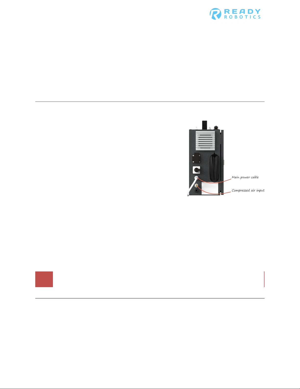
Connecting power and compressed air
The Forge/CTRL system requires 120V power and 90 psi of
compressed air to operate.
• Removing power from the system without safely shutting
down the system may damage the robot arm.
• Removing air from the system may prevent certain
peripherals and end effectors from working properly.
The power and compressed air inlets are located on the left side of
the system.
Power
The main power cable for the Forge/CTRL system must be attached to AC power for the system to turn on and
operate.
Compressed air
The compressed air connection takes a standard 1/4-inch industrial quick coupler. READY Robotics recommends
that air provided to the Forge/CTRL system be between 80 - 110 psi. Providing compressed air above or below this
range could cause the system to operate in an unexpected manner. Note: Your system’s set-up may differ.
Do not attach compressed air greater than 110 psi to the system.
Page 18

Forge/CTRL User Manual
Hardware Set Up
Version 2.0
Starting the system
Power on the Forge/CTRL
The Power Disconnect switch, on the left side of the Forge/CTRL provides the system with power. It does not start
up the system. Once the Power Disconnect is on and power is available, pressing the Power button starts up the
system.
Before turning the main power switch to the on position, ensure that AC power and compressed air are both
attached to the system.
Startup procedure
When the Power button is pressed, the system goes through its startup procedure. The monitor and TeachMate
LEDs turn on. While starting up, the robot arm may move slightly and make a clicking sound, and the monitor
displays a loading status. Allow the system to fully startup before attempting to use the system. When the system
is ready for use, the monitor displays the End User License Agreement in Forge/OS.
Page 19

Forge/CTRL User Manual
Hardware Set Up
Version 2.0
Step
Action
1
Rotate the Power Disconnect switch a quarter turn clockwise to the On position.
2
Press the Power button
3
Read through the End User License Agreement (EULA) and tap Accept.
Startup the system
Follow these steps to turn on and startup the Forge/CTRL system.
Result: Power is supplied to the system. The Forge/CTRL can be turned on.
Result: The green LED lights up and the startup procedure begins. When ready, Forge/OS displays the
End User License Agreement.
Result: The System Loadout screen appears.
Note: Declining the EULA or closing the EULA window causes the system to shutdown.
Attaching an end effector to the robot arm
End effectors attach to the robot arm by securing the end effector’s tool flange to the wrist flange. The wrist flange
at the end of the robot arm is designed to interface with a variety of end effectors provided by READY Robotics.
The tool flange connects to the wrist flange with the end effector in only one position. If an adjustment to the end
effector’s position needs to be made, to allow for clearance beneath the TeachMate for example, the tool flange
can be removed, adjusted, and reattached to the end effector.
Note: Extra and replacement tool flanges can be provided by READY Robotics for damaged flanges or custom end
effectors.
Page 20

Forge/CTRL User Manual
Hardware Set Up
Version 2.0
Step
Action
1
Release the locking bolt.
2
Line up the alignment pin on the wrist flange with the alignment slot on the tool flange. Push the two
3
Lock the locking bolt by pushing the locking lever all the way closed.
4
Configure the end effector in System Loadout, see the “System Loadout” chapter for more
• Define the center of mass (COM) of the tool.
Attach an end effector to the arm
Follow these steps to attach an end effector to the end of the robot arm.
a. Pulling button out on the end of the locking lever.
b. Pull the locking lever all the way open.
flanges together.
Result: The face of the tool flange is touching the face of the wrist flange.
information.
In System Loadout, you
• Receive instructions on how to attach the end effector’s air hoses or power cables to the
TeachMate.
• Provide the measurements for the tool center point (TCP).
Page 21

Forge/CTRL User Manual
Hardware Set Up
Version 2.0
When adding devices to the air or PLC modules, remember to select both the device and the correct
Forge/OS is not able to actuate the device in the task.
Step
Action
1
Determine the type of power needed for the device.
If the device is ...
Then ...
Powered by air
Connect the air hose to one of the air outlets on the stand.
A PLC
Connect the cable to the PLC module on the stand.
2
In Forge/OS, configure the device in System Loadout; see the “System Loadout” chapter for more
Attaching devices to the air and PLC modules
The air and programmable logic controller (PLC) modules are located on the right side of the Forge/CTRL system.
Your Forge/CTRL system comes preconfigured with modules depending on your task needs. The air modules take a
standard 1/4-inch industrial quick coupler.
module in System Loadout. If you do not select the device in System Loadout, Forge/OS does not
!
provide options to actuate the device in your task. If you select the incorrect module for the device,
Attach a device to the stand modules
Follow these steps to attach a device to the Forge/CTRL stand.
information.
Page 22

Forge/CTRL User Manual
Connect to a camera
Version 2.0
Connect to a Camera
Overview
Integrating a camera into your task can increase the flexibility of your system. The camera acts as the eyes of the
robot arm. Without the camera, you program the location of each workpiece the robot arm interacts with. The
result is manually programming several blocks and waypoints. This is fine in situations where the workpieces can
be presented in a consistent manner and Grid and Pattern blocks can be used. But what about times where
workpieces can’t be consistently presented?
A camera takes a picture of the work area, identifies the workpiece’s location, and saves the location. The robot
arm can then be programmed to move to the location and pick up the piece. Each time the camera takes a picture
of the work area, it updates the location of the workpiece it finds. So only one Robot Moves block needs
programmed.
Before you begin
Prior to setting up the camera’s software or setting up the camera in Forge/OS:
1. Ensure the camera is physically secured to the work area and has a clear view of the work surface.
2. Connect the camera to the Forge/OS device via the ethernet port.
Setup the camera’s software
Compatibility requirements
For a camera to be compatible with Forge/OS, the camera’s software must be set to send data over TCP/IP.
Forge/OS uses this information sent by the camera to identify the workpiece and its location.
Page 23

Forge/CTRL User Manual
Connect to a camera
Version 2.0
Network Setting
Value
Communication
TCP/IP
DHCP
Disabled
Static IP
172.16.255.254
Server Host
172.16.255.250
Port
8890
Terminator
String CR + LF
i Example of the guidelines applied to a Cognex
camera
Network settings
Use these network settings when setting up the camera. These settings will allow the camera to send information
to Forge/OS. In the camera’s software settings:
For information specific to setting up your camera with these settings, consult the Camera’s set up guide or your
camera integrator.
Information formatting
For Forge/OS to read the information sent by the camera, the
following formatting guidelines need to be applied:
• Left curly bracket, {, as the leading character
• Right curly bracket, }, as the trailing character
• Comma delimited text
• Labels in a ‘keyword’: format
Example: ‘angle’:
Page 24

Forge/CTRL User Manual
Connect to a camera
Version 2.0
Step
Action
1
Access System Loadout in Forge/OS.
2
Select Devices => Camera.
3
If your camera requires a calibration grid, place the calibration grid on the work surface.
3
Follow the on-screen wizard to:
3. Define the boundaries of the frame.
Setup the camera in Forge/OS
Follow these steps to begin the camera setup process in Forge/OS.
1. Test the connection.
2. Calibrate the tool center point (TCP).
Test the connection
To test the connection, place a workpiece on the camera’s training grid and press Test Camera Connection.
When you test the connection, Forge/OS validate the information it’s receiving from the camera. If the connection
is successful and the part is detected, you continue setting up the camera in Forge/OS. If the connection is
unsuccessful, to continue setup, check the camera’s software settings, update them as needed, and try again.
Calibrate the tool center point
Calculating the tool center point (TCP) of the probe helps Forge/OS gather information about the robot arm and
end effector’s orientation. This makes it easier for Forge/OS to create an accurate frame for the camera.
To calibrate the TCP, follow the on-screen guide to capture the probe in three different poses:
1. Pointing straight down.
2. Rotated at a 45º relative to the +X axis.
3. Rotated at a 45º relative to the -X axis.
Note: Refer to the images in the setup wizard for help with positioning the robot arm and probe.
Page 25

Forge/CTRL User Manual
Connect to a camera
Version 2.0
Step
Action
1
From the Blocks menu, select Checks > Camera.
Result: The settings for the Camera block appears.
2
Provide a name for the landmark that is created for the workpieces location and tap Accept.
Note: The landmark is used for pick and place tasks.
3
Select the new Camera block and, from the Execute menu, select Step.
Result: The landmark created by the Camera block can be referenced in Robot Moves blocks.
4
If using the camera for a pick and place task, assign the camera’s landmark to the waypoint of the
move block that brings the end effector on or above the workpiece.
Define the frame
To define the frame, establish two axes from three points, the origin point and two points extending out from the
origin point.
Things to consider while defining the frame:
• Begin the process by snapping the end effector to the Z axis of the stand frame.
1. Open the Robot Controls and set the Jog Mode to Jump.
2. Select Stand as the Frame.
3. Tap Snap Z Axis and Execute Jump.
• When jogging the arm along the axis indicated in the wizard:
• The direction of the jog controls may be different than what is indicated in Robot Controls.
• Two inches is the minimum distance required to define frame. Jogging the arm more than two
inches increases the accuracy of the frame.
Use the camera in a task
When executed, the Camera block takes a picture of the work area, identifies the workpiece, and creates a
landmark out of the information. Each time the Camera block executes, the landmark is updated based on the
workpiece’s location.
After placing a Camera block, step the block to establish its settings in Forge/OS.
The Camera block is available in the Checks section of the Blocks menu. Follow these steps to place a Camera block
in your task
Page 26

Forge/CTRL User Manual
Troubleshooting and Technical Support
Version 2.0
Issue
Cause
Solution
Power not attached
Verify that the power cable is attached to an active power source
Teach pendant is
Verify that the teach pendant is on and does not say "Robot
Teach pendant is
See below, "The Teach Pendant is showing an error."
Power not attached
Verify that the power cable is attached to an active power source
Monitor cables
Verify that the cables in the back of the monitor are firmly and fully
Monitor is not
Use the power button the right side of the monitor to turn on the
Robot Position
The robot arm was moved while the system was powered off. On
Robot Emergency
Clear the Emergency Stop by rotating the red button the Teach
System Emergency
The PLC is in error, turn the system off and unplug the Forge
Safety Violation or
Clear the Emergency Stop by rotating the red button the teach
Troubleshooting and Technical Support
Troubleshooting
Nobody’s perfect, and the Forge system is no exception. If you’re having issues getting the system to work as
expected, this section should provide some guidance on troubleshooting. If there isn’t a fix for your issue in the
manual, please contact READY Robotics via email or phone.
The Forge system
will not turn on
The Forge
system’s monitor
will not turn on
to Forge system
not on
showing an error
to Forge system
loose or unplugged
turned on
Verification (teach
pendant)
in your facility.
Alignment Error" or "Protective Stop Enabled". Verify that the
Teach Pendant emergency stop button is not pressed. If necessary,
turn on the teach pendant with the silver power button.
in your facility.
inserted.
monitor. Confirm that all power cables are attached before turning
on the monitor.
the Teach Pendant, clear the error by checking the box to confirm
the pictured orientation is the same as the arm orientation. Then
press "Robot Position Verified". When the error is cleared, turn the
robot on from the Robot Control Panel.
Stuck on Begin
screen/the Teach
Pendant is
showing an error
Stop
Stop (teach
pendant)
Safety System Fault
(teach pendant)
Pendant clockwise until it pops out. When the button is cleared,
turn the robot on from the Robot Control Panel.
system from power. Wait 5 seconds, the plug the system in and
turn it back on.
pendant clockwise until it pops out. When the button is cleared,
Restart the robot from the teach pendant. If the teach pendant
returns "low voltage", clear the error and Restart the robot from
the teach pendant again. If the system still does not restart, shut
down the Forge system with the main power switch.
Page 27

Forge/CTRL User Manual
Troubleshooting and Technical Support
Version 2.0
Issue
Cause
Solution
Air not attached to
Check that the air hose is attached to the stand and that air is
Gripper is not
Confirm that the air hoses or power cable are in the correct
Gripper is not
Select Open Robot Config from the Robot Control Panel and select
Air not attached to
Check that the air hose is attached to the stand and that air is
Peripheral is not
Confirm that the air hoses or power cable are in the correct
Peripheral is not
Select Open Robot Config from the Robot Control Panel and select
Teach pendant is not
Verify that the teach pendant is on and does not say "Robot
Emergency Stop
Rotate all Emergency Stop buttons clockwise so that the button
The incorrect end
If the incorrect gripper is configured, the arm will compensate for
Forge/OS or the
Software and/or
Restart the Forge system using the main power switch. After the
Troubleshooting - continued
End effector is not
working as
expected
Device is not
working as
expected
Forge system
attached to the
Forge system
properly
selected on robot
configuration panel
Forge system
attached to the
Forge system
properly
selected on robot
configuration panel
flowing. Verify that the lockout valve is pulled up and air is not
leaving through the valve. The taskbar Fan icon should be green.
numbered input and that they are firmly and fully inserted. The
Robot Config screen shows which ports take which air hoses.
the gripper is that attached to the Forge system arm. Be sure to
attach the peripheral to the chosen end effector slots.
flowing. Verify that the lockout valve is pulled up and air is not
leaving through the valve. The taskbar Fan icon should be green.
numbered input and that they are firmly and fully inserted. The
Robot Config screen shows which ports take which air hoses.
the peripheral is that attached to the robot arm. Be sure to attach
the peripheral to the chosen air module.
Robot arm is not
responding to
Forge/OS
commands
Robot arm is
unable to support
its own weight
robot arm are very
slow to respond
on
button is activated
effector is
configured
driver issues
Alignment Error" or "Protective Stop Enabled". If necessary, turn
on the teach pendant with the silver power button.
pops out. Use the Robot Control Panel to turn the robot on.
the wrong weight. From the Robot Config screen, select the
gripper that is on the end of the robot. Or select "No Gripper" and
remove the end effector from the robot arm.
system has shut down, wait ten seconds, then turn it back on
again.
Page 28

Forge/CTRL User Manual
Troubleshooting and Technical Support
Version 2.0
Issue
Cause
Solution
Force sensor is not
Verify that the force sensor is firmly and fully attached to the
Force threshold is
Raise the force threshold in the force blocks. A low threshold (<10)
Software and/or
Restart the Forge system using the main power switch. After the
Stabilization legs are
Lower the stabilization legs so that they are making full contact
Object is not secure
If multiple waypoints are off by the same amount, the object the
Gripper is in
Verify the gripper is mounted in the same orientation as when the
Landmarks were not
Manage the landmarks for the task by opening a waypoint block
Troubleshooting - continued
Force blocks are
not working as
expected
Robot arm is not
accurately hitting
waypoints
plugged in
too low
driver issues
not in place
incorrect orientation
TeachMate. If needed, use pliers or a small wrench to tighten the
wire cap against the TeachMate.
may fail unexpectedly on high speed motions or in a facility with
ambient vibrations
system has shut down, wait ten seconds, then turn it back on
again.
with the floor and the stand can no longer roll on its wheels.
Tighten the locking nuts (underneath the Robot) against the
bottom of the Robot with a wrench so that they cannot be
loosened by hand.
robot arm is moving to may have moved. If the object is on the
stand, firmly secure it into place with multiple screws. If the object
is mounted to another object, firmly secure it to the object with as
many connection points as possible.
waypoints were programmed. There are up to four rotations that
each gripper can attach to the wrist at. If the gripper articulates
and has changed positions since the waypoints were initially
programmed, you may either need to reprogram the waypoints or
realign the gripper joints.
updated after
moving Forge
system
and hitting Manage Landmarks. Use the R-Align Probe to update
the landmark to the R-Align Socket. Save the new landmark and
verify that the waypoints are now correct.
Page 29

Forge/CTRL User Manual
Troubleshooting and Technical Support
Version 2.0
Issue
Cause
Solution
A waypoint is
Check that a waypoint is not repeated consecutively, either by
The blend is a
A blend move is not the most reliable block for a rotation-only
Vector block is not
The vector is a
A vector move is not the most reliable block for a rotation-only
Jog block is not
Driver issues
Restart the Forge system with the main power switch.
Email not configured
Verify that the email address is entered properly and spelled
Network not
Verify that the network settings are correct in the Setup Network
Troubleshooting - continued
Blend block is not
working as
expected
working as
expected
working as
expected
Email Notifications
are not working
repeated
consecutively in the
blend
rotation-only motion
rotation-only motion
or configured
incorrectly
properly configured
name or position, in the blend. Select each waypoint in order and
press "Move To" to confirm that each waypoint is different.
motion. Use a rotational jog instead.
motion. Use a rotational jog instead.
correctly. Select the desired email address from the dropdown list
in the Task Info screen or in the Breakpoint block.
screen. Choose the correct network for your facility and verify that
the password, if needed, is entered correctly. Contact your
network administrator for help if you are unfamiliar with these
settings.
Technical Support
If the troubleshooting information doesn’t address your Forge system’s bug, reach out to us with the Report Issue
feature via the READY menu in the lower left corner. READY Robotics recommends using the Report Issue feature
before contacting technical support, as the issue report will help us pinpoint the problem in your system and
significantly reduce the time to troubleshoot.
• Email READY Robotics: support@ready-robotics.com
• Call READY Robotics: 410-914-8230
Page 30

Forge/CTRL User Manual
Technical Specifications for the Forge/CTRL
Version 2.0
Power Requirements
Power Consumption without peripherals
Voltage
Main Power Input: 120V VAC
PLC Inputs:
(See Siemans S7-1200 Functional Safety Manual for more information)
Type
Sinking PNP
Rated voltage
24 V DC at 4 mA, nominal
Continuous permissible voltage
30 V DC, max.
Logic 1 signal (min.)
15 V DC at 2.5 mA
Logic 0 signal (max.)
5 V DC at 1 mA
Cable length (meters)
500 m shielded, 300 m unshielded
PLC Outputs:
(See Siemans S7-1200 Functional Safety Manual for more information)
Type
Solid state - MOSFET (sourcing)
Current (max.)
0.5 A
Logic 1 signal at max. current
20 V DC min
Logic 0 signal with 10 KΩ load
0.1 V DC max
Surge current
8 A for 100 ms max.
L+ -48 V DC, 1 W dissipation. External Supression must be used for most
Cable length (meters)
500 m shielded, 150 m unshielded
Air Requirements
Main Air Input:
80-100 psi
4mm Push to Connect Fittings
1/4 Industrial Quick Disconnect Fittings
Category 3, Performance Level (PL) d in accordance with EN ISO
Mechanical:
Weatherproofing
IP54
Max Operating Temperature
50 degrees C (does not include end effector peripherals)
Min Operating Temperature
0 degrees C (does not include end effector peripherals)
Payload
Teachmate + Force Sensor:
1.54 lbs (0.7 kg)
Force Sensor:
0.66 lbs (0.3 kg)
Teachmate:
0.88 lbs (0.4 kg)
Arm Speed typical tool:
1 m/Sec. / 39.4 in/Sec. for all
Technical Specifications for the Forge/CTRL
System technical specifications
The follow section includes any technical specifications that may help setup your Forge system. If you have
questions that aren’t answered by the information in this section, please reach out to us right away.
Inductive clamp voltage
Air Output (TeachMate)
Air Output (Air Modules)
Safety Rated Air Ouputs
inductive coils
Same psi as input
Same psi as input
13849:2008
Page 31

Forge/CTRL User Manual
Technical Specifications for the Forge/CTRL
Version 2.0
Force sensor threshold values
If the troubleshooting information doesn’t address your Forge system’s bug, reach out to us with the Report An
Issue feature. The below values are the amount of force applied in pounds when the force sensor is triggered for a
motion in +Z in a jog block with an end effector that is calibrated from the Setup Tool screen.
Solid line values are tested, dotted line are extrapolated.
Applied Force in +Z (lbs) by Threshold
20
18
16
14
12
10
8
6
Force to Trigger (lbs)
4
2
0
10 20 30 40 50 60 70 80 90 100
y = 1.4344x + 2.8864
Force Threshold
 Loading...