

Ready Remote 23926 Installation Manual
®
Ready Remote
Model 23926
Remote Control Car Starter Installation Manual
DesignTech International, Inc. • 7955 Cameron Brown Court • Springfield, Virginia 22153 USA • www.designtech-intl.com • 703-866-2000 or 800-337-4468
PLEASE READ ENTIRE MANUAL COMPLETELY BEFORE BEGINNING INSTALLATION
Congratulations on your purchase of the Ready Remote Car Starter. Ready Remote Car Starter allows you to start the car by remote control from the comfort
of your home or office in order to cool it down in the summer or warm it up in the winter.
Ready Remote Car Starter is for
automatic transmission/fuel injected gasoline vehicle only. Please see pages 5-6 for important information on vehicles with
factory anti-theft systems. Ready Remote is an extremely sophisticated system with multiple built-in safety and security features.
Ready Remote® Remote Car Starter:
• Will start your car by remote control, and run the heater,
defroster, or air conditioner to warm up or cool down the car
from up to 800 feet away!
• Is designed to start the car if it is in park, and only if the
hood is closed.
• Will attempt to start the car for up to six seconds, but no
longer (to avoid damage to the starter motor). Should the
car not start, or if it stalls after starting, the remote starter
will make two further attempts to start it.
• Will not let the car be driven without the key in the ignition.
• Allows you to use one remote to control up to 4 vehicles with
Ready Remote
®
Remote Car Starters.
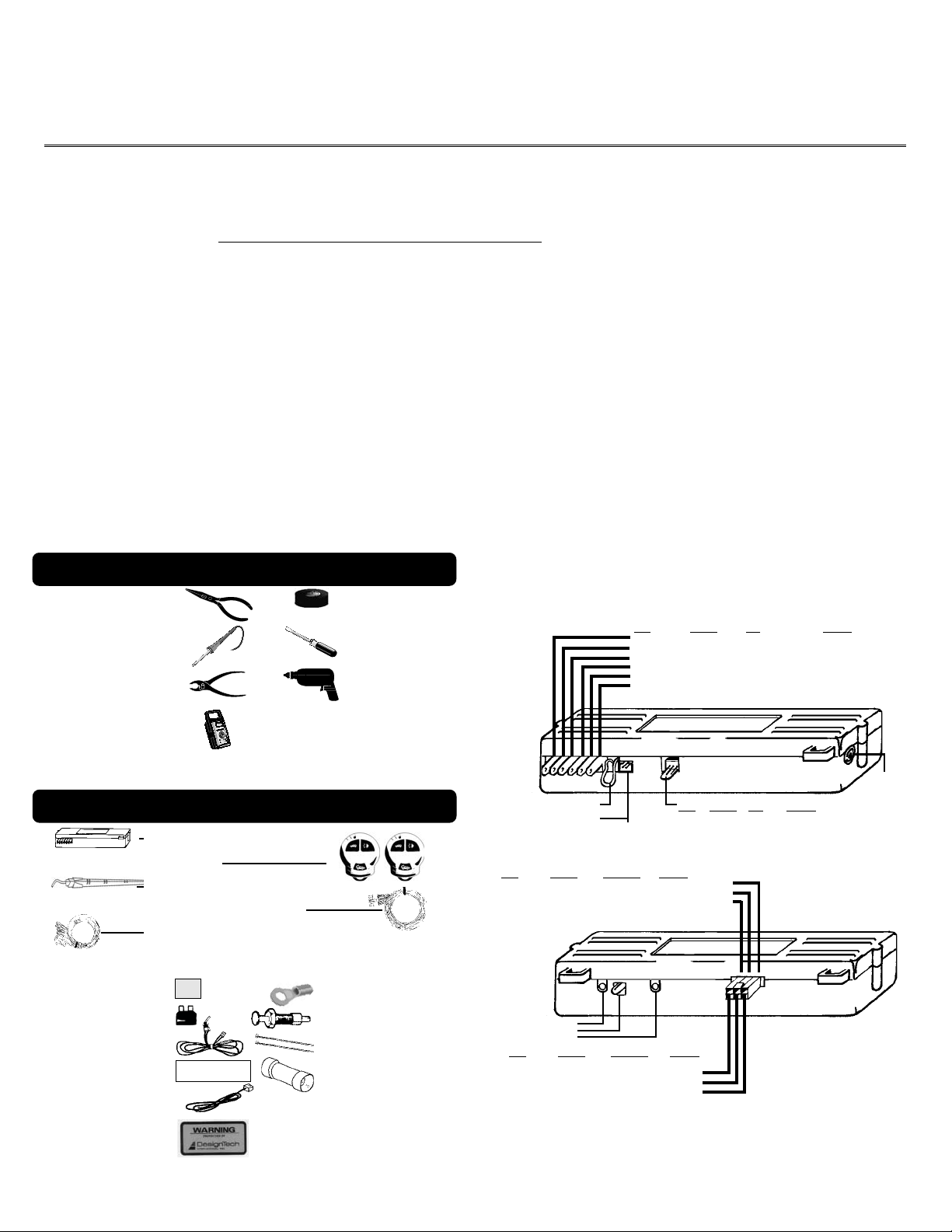
Tools required to install the Ready Remote® Unit:
Wire Cutters/Strippers
Soldering Iron
Pliers
Test meter
Electrical Tape
Screwdriver
Drill with
1
/4”and 5/16”
drill bits
• Requires the user to “enable” the unit to prevent accidental
starts.
• Shuts itself off automatically after 10 or 15 minutes
(programmable) if you forget to come out to your car.
• Starts the vehicle automatically when ever the temperature
drops below 0°F (-18°C) when the Cold Start™ option is
activated
• Will shut off if the brake pedal is pushed, the hood is opened,
or the transmission is shifted out of park - unless the key is
in the ignition and in the “run” position.
• Is quality engineered, microprocessor controlled, and made
in the USA to provide many years of reliable use.
• Comes with a Two Year Limited Warranty.
Wiring Diagram
Power Harness
Color Function Type Required
Pink Power (+12V) Input Yes
White Accessory Relay output Yes
Yellow Starter Relay output Yes
Blue Ignition 1 Relay output Yes
Green Ignition 2 Relay output Consult Wiring Guide *
Black Ground Input Yes
Circuit
We highly recommend that all connections be soldered for reliability.
Parts List included with the Ready Remote® Unit:
Remote Starter Receiver Module
Transmitters
Antenna
Control Harness (6 position)
6 Power & Ignition Wires
The following parts are included in the plastic bag:
Alchohol
Alcohol Pad
Green 30 A Fuse
On/Off Control Switch
Warning Label
Single Blue Horn Wire
2 Protected by
DesignTech Labels
Pad
WARNING
This car is equipped with a remote control starting device.
Disable before working on car!
AVERTISSEMENT
Co véhicule est équipé d’un systéme de démarrage á distance. Mettez-le hors
fonctuin avant d’eflectuer toule opération d’entretian ou de répanation!
Ring Terminal
Hood Pin Switch Set
2 Cable Ties
Yellow Butt Connector
GREEN In Gear Loop
ON/OFF Switch Jack
Color Function Type Required
Blue Horn (-)400mA No
Control Harness
Color Function Circuit Type Required
Brown/White Alarm Disarm (–)400 mA Consult Wiring Guide*
Yellow Lights (+) Relay Output No
White/Black Ignition #3 (–) 400 mA Consult Wiring Guide*
White - Option
Red LED Light
Red - Code Learn
Color Function Circuit Type Required
Orange Brake (+) Input Yes
Purple Hood Switch (-) Input Yes
Green Tach (-) Input No
* For free vehicle specific wire information consult
our website at www.designtech-intl.com
1
Circuit
Coax
Antenna Jack
v2.2 (2126)
On cars with airbags, you may notice bright yellow tubes
or harnesses marked SRS (Supplemental Restraint System) underneath the steering column area. DO NOT tamper
with these wires in any way, to prevent personal injury
and/or damage to the air bag system.
On GM rear-wheel drive vehicles built prior to 1995 and
Dodge Dakota trucks built prior to 1996, see the last page
of this instruction manual.
Battery gases are explosive.
Do not smoke while working near the car’s battery.
Note:
Some installers connect a battery charger to the vehicle’s
battery during installation. This is fine, but it must be removed before running the vehicle under remote starter control.
When running the wires through the car’s firewall, be sure
to protect them from sharp metal edges and from hot
surfaces on and around the engine.
INSTALLATION INSTRUCTIONS
1. Before You Start
Take the time to read through the whole installation manual before
beginning.
Always leave a window open to avoid locking your keys in your car.
IMPORTANT:
After having read the entire manual, start the installation by putting the yellow WARNING STICKER in the engine compartment. Choose a surface that is clean and readily visible when
the hood is open.
This car is equipped with a remote control starting
Ce véhicule est équipé d’un systéme de démarrage a distance.
WARNING
Disable before working on car!
device.
AVERTISSEMENT
POWER & IGNITION HARNESS
The remote starter module will be installed under the dash once all
wiring has been completed. Do not mount the module at this time!
You will need to check the red diagnostic LED light as the installation progresses. Locate (or drill) a hole in the firewall to run the
PURPLE and GREEN wires of the Control Harness and the PINK wire
of the
Power harness
short wires stay in the passenger area. Leave about a foot of the wire
harness under the dash for ease of working and visual access to the
diagnostic light.
The Installation Information section of our web site
www.designtech-intl.com is available 24 hours/day to provide
you with free, up-to-date vehicle wiring information for your particular vehicle after you log in.
Note: Always connect the
any of the other wires. Do not insert the fuse until step 11.
2. Black Wire (16 AWG) - Ground
Connect the BLACK
driver’s kick panel area. Use the small ring terminal. (The metal
bracing around or beneath the dash board is not always adequate.)
3. Pink Wire (12 AWG) - Power (+12 Volts)
Connect the ring terminal at the end of the short PINK
Volt terminal of the battery. Run the long pink wire through the
firewall of your vehicle. Join the remaining ends of the power wire
together by soldering them. Tape with electrical tape to leave no
v2.2 (2126)
into the engine compartment. The remaining
Pink
and
Black
wires before connecting
wire to a very good, clean chassis ground in the
wire to the +12
exposed wires. Alternatively, you may wish to use the yellow butt
connector, but we recommend soldering. Wait to insert the 30 amp
green fuse into the holder until step 11. As the power is first applied
to the unit the red diagnostic LED light will blink once.
Note: Failure to properly install the fuse holder and 30 amp fuse to
the pink wire to the battery voids all product warranties.
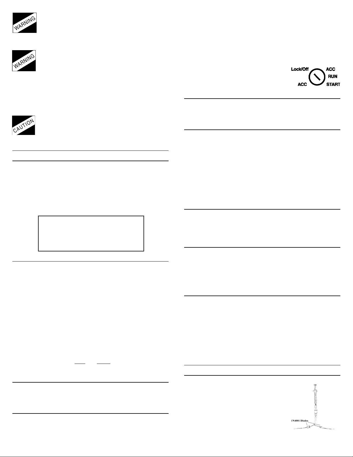
Ignition Key Diagram for Steps 4-7
The vehicle’s wires are found coming off of
the key switch. Remove the panel under the
steering column to access these wires.
4. Blue Wire (14 AWG) - Ignition 1
Connect the BLUE wire to the ignition 1 wire of your vehicle. This wire
will measure +12 Volts on the test meter in the “run” and
position, and is off in the “lock/off” and “accessory” position.
5. Green (14 AWG) - Ignition 2
Connect the GREEN wire to the Ignition 2 wire in the vehicle. The
Ignition 2 can function in serveral different ways in your vehicle. It is
important to understand how it works. The Ignition 2 will usually mea-
sure +12 Volts in the “run” position and is off (ground) in the “lock/
off” and “accessory” position. In certain vehicles, it may also show
+12 Volts in the “Start” position or Ignition 2 may turn OFF during
“Crank” and turn back ON after the starter disengages. Carefully note
the function of the Ignition 2 wire. If the Ignition 2 turns OFF during
“Crank,” see Changing Ignition 2 Function in section 21. If Ignition 2
stays ON during “Crank,” no options need to be changed.
6. White Wire (14 AWG) - Accessory
Connect the WHITE wire to the accessory wire which is +12 Volts in
the “run” and “accessory” position, but off in the “start” and “off”
positions. In GM vehicles, connect the white wire to the (usually orange) wire that is hot in “run” only.
7. Yellow (14 AWG) – Starter
Connect the
YELLOW wire to the starter wire. This wire will measure
+12 Volts on the test meter in the “start” position only.
Note:
Most Nissan vehicles have two starter wires. Connect both
starter wires of the vehicle to the
YELLOW start wire of the remote
starter.
8. Plug-In On/0ff Switch
Connection of the ON/OFF control switch is mandatory. Do not let the
switch wires touch ground. Mount the control switch so that it is
easily accessible and so that the “ON” position is facing upward.
Make sure there is enough clearance behind the mounted switch for
the wire connections. Use a 1/4" drill-bit for the mounting hole. Plug
the switch connector into the module just to the right of the power
wires. Turn the switch on.
CONTROL HARNESS
(ALL WIRES ARE THE SMALLER 18 AWG SIZE)
9. Purple Wire - Hood Pin Switch - Control Harness
The hood pin switch MUST be installed with
the remote starter. It prevents operation of
the remote starter when the hood is open
and is used to initialize the unit. Connect
the PURPLE wire to the hood pin switch using the red connector.
Note:
If you already have a hood pin switch
which is being used by a car alarm system,
2
To Alarm
How to share a hood pin
To Remote Starter
switch with an alarm
“start”

you may share the wiring – but be sure to diode isolate each wire
going to the hood pin switch with the bands of diodes pointing
towards the pin switch as shown.
10. Orange Wire - Brake Shut-off - Control Harness
Connect the ORANGE wire to the brake wire which receives +12 Volts
when the brake pedal is depressed. This wire must be connected. It
arms a critical safety feature which disables the remote starter when
the brake pedal is depressed.
Note:
In some cars, the ignition must be in the “on” position to test
the power in the brake wire.
Note:
If the Ignition 1 & Ignition 2 wires come on whenever the
brake is depressed and the hood is open this just means you need
to initialize the unit in Step 11.
11. Initializing the Remote Starter
BEFORE UNIT WILL DO ANYTHING FOR THE FIRST TIME, YOU MUST
INITIALIZE THE REMOTE STARTER
A. Insert the fuse into the pink fuse holder on the pink power wire.
B. Turn the control switch on.
C. The remote starter requires the installer to open the hood and
then press and hold the brake pedal. Note: The ignition/dash lights
will come on if the unit is not initialized.
D. While depressing the brake (with the engine off and the hood
open) turn the ignition key to the “RUN” (not “start”) position.
E. Put the car in “DRIVE” from the “PARK” position.
F. Put the car back in “PARK” and release the brake.
G. Turn the key off and remove the key.
Note:
Confirm initialization by turning the ON/OFF control switch “OFF”
and then “ON”. The red LED light on the remote start module will
flash once immediately as the switch is flipped from the “OFF” to the
“ON” position.
If the unit is not initialized then the dash lights will come on (the
remote starter powers up the ignition wires) when the brake is depressed or the hood is open, and the control/valet switch is on. REPEAT STEPS A THROUGH G. See the colored Trouble Shooting Sheets
if necessary.
12. Green Wire - Tach Input - Control Harness
The remote starter has two ways of monitoring the car during the
starting process. Both ways will ensure a clean, accurate start. Read
about both methods before deciding which one to use. Normally you
should try the “No Tach™”
method first.
“No Tach™” Starting
This starting method does not require the connection of the GREEN
tach wire. This method will start the car by reading the car’s voltage
before attempting to start, and then looking for a voltage increase
when the alternator kicks in. This feature automatically takes into
account voltage, temperature, and the time since the vehicle was last
””
”
””
™™
run. The “No-Tach
™
starting is preset at the factory and you can
™™
skip step 12A if you would like to use it. Note that if the vehicle is
hard to start, set option 3 (Setting Program Features section (step
20)) for “extended crank.”
Tachometer sensing
If the vehicle is generally hard to start (i.e. requiring a cranking time
of more than 1 second) you will get more accurate starting with the
tachometer sensing starting method. This method starts the car by
reading the engine speed (tach) information from a wire under the
hood. If you choose tachometer sensing, connect the GREEN (18
awg) wire to the car’s tach wire under the hood (normally the negative side of the coil or tach output of coil pack). After you have
connected the GREEN wire, you need to teach the remote starter the
vehicle’s tach rate at idle. Proceed to step 12A.
Note:
You must have already initialized the remote starter in Step 11.
12A. Tach Rate Learning
Note:
Only use if the tachometer sensing method is chosen.
A. Connect the GREEN wire to the car’s tach wire under the hood.
B. Turn the On/Off control switch to the “OFF” position. Wait 5 sec-
onds for the red LED light flashes to stop.
C. Program the unit to the tach mode by pushing the White “op-
tion” button once and watching the red LED light flash. Now
push the middle button on the transmitter for a second until you
see the red LED light flash again. You are now in TACH mode. (If
the LED light flashed twice or sometimes three times – simply
push the transmitter button again until you get only one flash).
D. Wait 5 seconds for the red LED light to flash 3 times.
E. Turn the On/Off control switch back to the “ON” position
F. Start the car with the key and let it get to a
normal
idle. Do not
press on the gas pedal.
G. Push the red “code learn” button for a second.
H. Watch the red LED light. It will come on after 3 or 4 seconds,
indicating that the idle rate has been learned.
I. Watch the LED light stay on steady as the vehicle is running and
goes off as you rev the rpms above twice the idle rate. The LED
light must go out when you rev it above twice the idle rate to
confirm correct tach learning.
J. Turn the key to the “Lock/Off” position. You are now finished.
K. Turn the On/Off control switch off and the red LED light will go
out.
Note:
Once these steps are complete – you cannot use the red LED
light to confirm the tach idle rate again. You can however repeat the
above steps to learn tach over again at any time.
OPTIONAL STEPS
13. Yellow Wire - Headlights/Parking Lights - Control Harness
Connection of the YELLOW wire allows you to activate the low beam
headlights or parking lights to show the vehicle has remotely started.
After the remote starter has started the car, the lights will remain on
until the remote starter shuts off after 10 minutes, or when the brake
pedal is pushed, or when vehicle car is put into gear.
+12 Volts output. Connect the
YELLOW wire to the wire that has
power when the lights are on. You do not need to add a relay unless
your vehicle has a negative lighting system.
14. Blue - Horn/Siren - Single Small Blue Wire
The BLUE wire, which is optional, signals the horn to honk once each time
the remote starter starts the vehicle. Connect the blue wire to the factory
horn wire, which is often found running down the steering column. It will
normally show +12 Volts at rest and the voltage will disappear when the
horn is honked. This is a 400 mA transistor ground output. If your vehicle's
horn requires a positive input, you will need a relay.
15. Brown/White - Alarm Disable - Control Harness
The BROWN/WHITE wire, which is optional, is Alarm Disable,
which will give out a quick negative pulse just before starting the
vehicle. This wire can be used to turn off the factory alarm system
in vehicles which have them. In most vehicles, this wire is located
in the driver’s kick panel. A relay is needed for vehicles which require a positive pulse.
This is a relay
3
v2.2 (2126)

16. White/Black Wire - Ignition 3 / VATS - Control Harness
The WHITE/BLACK
ground output that acts just like
the Ignition 1 or Ignition 2 relay
outputs (active in the “run” and
“crank” positions). This wire is
a 400 mA negative transistor output and MUST be set up to power
a relay
(not included). It can be used to power the third ignition wire
wire, is a
White/Black Wire
From
Remote Starter
Ignition 3
87
87A
85
30
86
To LARGE 12 Volt
Constant Wire
(Found in Ignition
Switch Wire
Harness)
To Additional
Ignition Wire
(in vehicle)
at the key (necessary for most Ford vehicles).
This is the wire that can also be used to bypass a passive anti-theft
system by hooking it up to the Universal Alarm Bypass Module. See
the Factory Anti-Theft Systems section at the end of the instructions.
REQUIRED FINAL STEPS
You must have hooked up all required wires and completed Initialization (Step 11) to proceed forward.
17. Trying the Unit Out
WARNING: Be prepared to apply the brake during this testing.
A. Close the hood and fully apply the emergency brake
B. Place the vehicle in Park.
C. Turn the On/Off switch off then on – the red LED light will flash
once.
D. Once all the wiring is checked and is correct, press the Start
button on the transmitter.
E. The car should start and continue to run for ten minutes. Make
sure that the engine shuts down if the car is taken out of park,
the hood is opened, the brake is pressed or the transmitter button is pushed again. If the car does not start, see the Code Learning section under Special Cases.
18. The Antenna
Feed the antenna around under the dash and up the inside of the right
or left windshield post and over the top of the windshield. Clean the
windshield with the provided alcohol pad for maximum adhesion.
Let the windshield dry for a minute. Peel the liner off the back of the
adhesive tape and mount the antenna behind the rear view mirror.
The more exposed the antenna is, the better the range performance.
Now plug the end of the antenna into the remote starter module. In
most vehicles you will get better range performance if the antenna is
pointing vertically downward from the top of the windshield.
The wiring section of the installation is now complete.
all unused wires so as to prevent short circuits, and mount the
module securely under the dash. When tying up and mounting the
unit, be sure to avoid any moving parts (steering column, pedals)
and sharp edges.
19. Trouble Shooting with the Self Diagnostics
The remote starter contains a built in diagnostic routine that will
indicate why the unit started or why the unit turned off the car the last
time that the unit was used.
To activate the diagnostic mode for why it turned off, simply turn the
On/Off control switch to the “OFF” position. In a few seconds, the red
LED light on the module will flash 1 to 12 times to identify the problem. See the chart below for an explanation of the flashes:
1 flash 10/15 minute time out. Unit should be fine. Make sure
the transmitter is working properly.
v2.2 (2126)
Be sure to cap
2 flashes Unit turned off because Brake or Hood was activated.
Check to make sure the hood pin switch is depressed
when the hood is closed and the correct brake wire is
hooked up.
3 flashes No Tach or Stalled. Review Step 12 and make sure the no
tach feature or the tach wire (if used) is programmed
correctly.
4 flashes Received another remote input from the transmitter
5 flashes Transmission was shifted into gear. Cut the small green
in-gear wire loop coming out of the receiver module.
6 flashes Low battery voltage, or may be missing an ignition wire
which powers up the alternator
8 flashes Over current - One of the 400 mA (-) transistor outputs
(alarm disable, Ignition 3 or horn) of the control harness
are driving too much current. Make sure to use a relay
where necessary.
12 flashes The Control Switch was turned off while the car starter
was running.
20. Setting Program Features:
The remote starter unit has many special features available. You will
not need to use these special features in most situations. The factory
settings will operate most vehicles. You must turn the On/Off control
switch to the “OFF” position to program any features. Note that
when turning off this control switch, the red LED light will flash a few
times, giving the diagnostic code described in Section 19. Wait a few
seconds for it to finish before programming your new Options.
Feature # Factory Setting (2 flashes) Option (1 flash)
1 “No-Tach” Tach Mode
2 10 Min. Run Time 15 Min. Run Time
3 Normal Crank Extended Crank
4 Normal Super Crank
5 Normal Voltage Metering Ignore Voltage Metering
6 N/A N/A
7 “Enable” feature No “Enable”
8 Normal DaytimeRunning Lights
Option #1
No-Tach Tach Mode
This option sets the starting method. The factory setting uses “NoTach” starting. If you wish to use the tach to start, follow the instructions in the Tach Rate Learning section (step 12A).
Option #2
10 Min. Run Time 15 Min. Run Time
This option gives you a choice of run times.
Option #3
Normal Crank Extended Crank
This option will add 50% more crank time to the NoTach™ starting
feature.
Option #4
Normal Super Crank
This option will add 100% more crank time to the NoTach™ starting
feature.
Option #5
Normal Voltage Metering Ignore Voltage Metering
This option is used in the “No-Tach” starting method when the alternator does not turn on quickly after the vehicle is started.
Option #7
“Enable” Feature No “Enable”
This option cancels the “enable” mode safety feature. The “enable” mode requires that the driver toggle the ON/OFF control swith
“OFF” then “ON” each time the driver removes the key from the
ignition in order to “enable” the vehicle for remote starter control.
This feature guards against undesired starting of the vehicle by
remote control.
You must keep this option as enable on all GM rear-
wheel drive and Dodge Dakota vehicles manufactured prior to 1996.
4
 Loading...