

ReadyNet WRT-500 Quick Installation Manual
Step 2: Wireless Security Setup
Your router is pre-configured with wireless security
from the factory. The default wireless pass phrase
is printed on the sticker on the bottom of the router.
If you would like to change the factory-set pass
phrase, click ‘Wireless’ then ‘Wireless Security’.
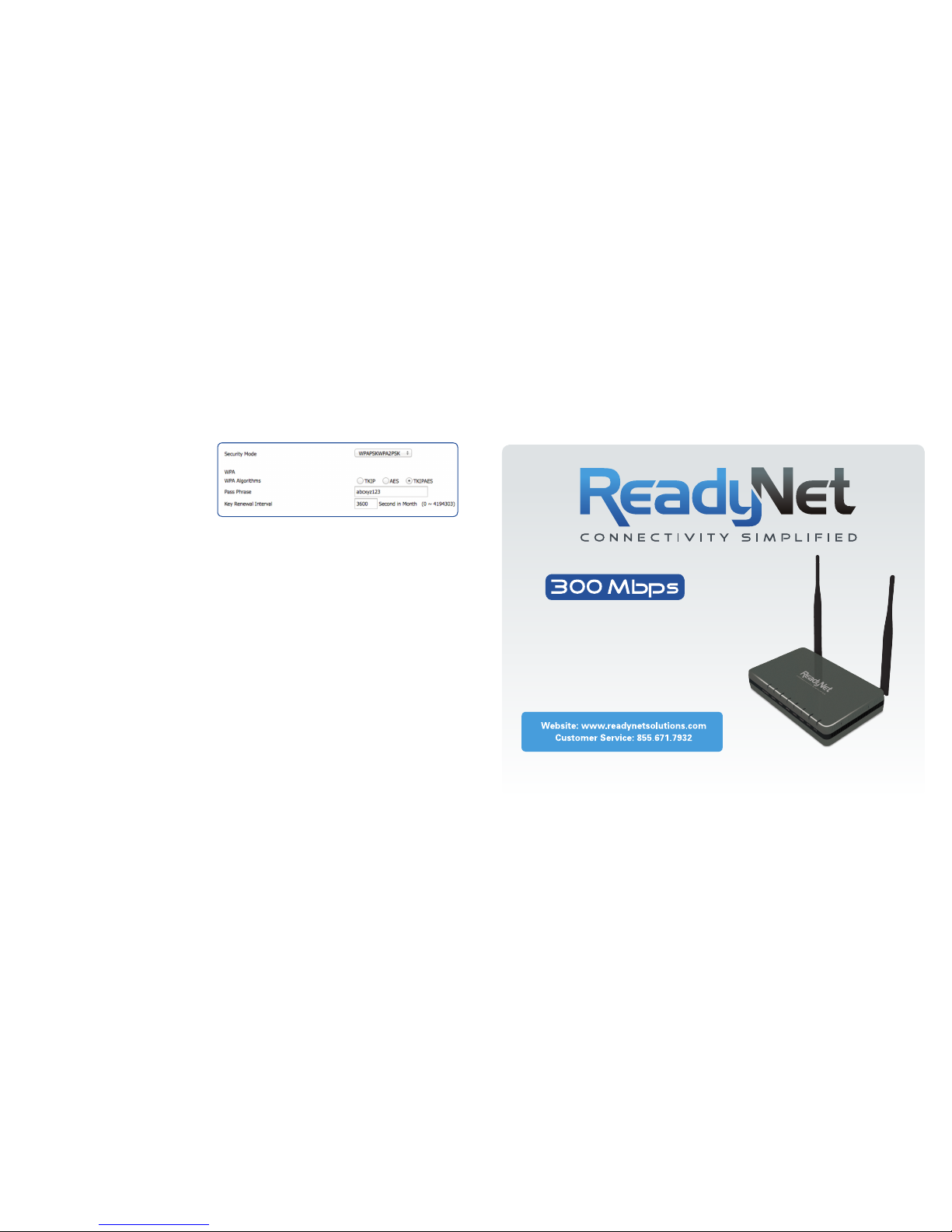
If, for example, you want to use WPA-PSKWPA2-PSK
as the Security mode, TKIPAES as the WPA algorithm,
and abcxyz123 as the pass phrase, your setting would
be like Figure 3
IMPORTANT: Click the ‘Reboot’ button at the bottom of the page to save your settings.
D. Setting Up Your Wireless Devices
Your wireless devices (desktop, laptop, iPad, smart-phone,
etc.) must be configured to work with your wireless router.
Each of these devices must have an internal or external
wireless adapter and applicable drivers. User guides for
each of these devices should have instructions for wireless
set up. You will need the SSID and password you assigned
to this wireless router during router set up. For each
wireless device, access the setup menu, choose the
appropriate SSID from the list of wireless networks, enter
your password, and test the wireless connection.
Quick Installation Guide
WRT500
Wireless N Router
Your WRT500 has been pre-configured with an SSID
(wireless network name) and security pass phrase.
See the sticker on the bottom of your router for this
information. If you wish to change these or other
settings, use the following instructions.
Figure 3
B. Configure Your Computer to Operate with the WRT500 Router
1. The network settings of your computer operating system must
be set to automatically obtain an IP address and to automatically
obtain a DNS Server Address.
2. Type “http://192.168.11.1” in the Address field of your web
browser and press the “Enter” key. A User Name and Password
dialog box will appear. The default User Name is “user” and see
the sticker on the bottom of your router for the default password.
Enter the user name and password then click the “Login” button.
Note: The default wireless IP address for the wireless router is 192.168.11.1 and the default Subnet Mask is 255.255.255.0
C. Configure Your WRT500 Router
1. WAN Connection Type
Click Network and then WAN. Change the
‘Internet’ field based on instructions from your
ISP. DHCP is the easiest to set up. Other
options available are Static and PPPoE.
Click ‘Save’.
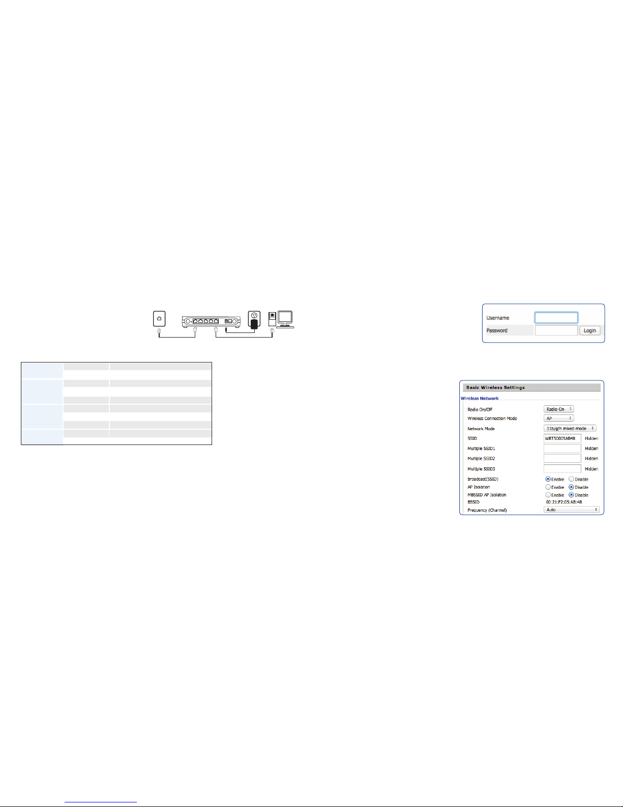
2. Basic Wireless Settings
To access the Wireless settings, click
‘Wireless’ and then ‘Basic’. The pre-configured
settings on this page will be appropriate for most
settings. You might want to change the SSID and
Frequency (Channel) fields.
Click ‘Save’ to move to the final step.
LED Indicator Status Description
Wi-Fi
On (Green) Wireless access point is ready
Blinking(Green) It will blink while wireless traffic goes through.
LAN
1/2/3/4
On (Green) The port is connected with 100Mbps
Off The port is disconnected
Blinking(Green) The data is transmitting
WAN
On (Green) The port is connected with 100Mbps
Off The port is disconnected
Blinking(Green) It will blink while transmitting data.
POWER
On(Red) The router is powered on and running normally
Off The router is powered off
A. Connect the WRT500 Router to Your Computer
1. To set up your router for the first time, please
connect the router to your desktop or laptop computer
as shown in the following diagram. Your broadband
Internet access will generally be from a cable modem,
ADSL modem, or similar device.
2. After the hardware connections have been completed, check
the status of the LED Indicators using the following table:
RST WAN LAN1 LAN2 LAN3 LAN4
SWITCH
DC5V2A
WRT500
Power Outlet
Broadband Internet
Figure 1
Figure 2
Note: If the LED indicator
is not displaying a “Normal
Status” as described in the
table at left, please check
the associated hardware
and connections.
Safety Notice
• The device should be placed on a flat horizontal surface, or secured safely to a wall.
• Operate equipment away from heat sources.
• Provide good air ventilation.
• Keep away from water and damp areas.
• Disconnect power from the device during severe thunderstorms.
• Use only the included AC power adapter.
• Keep router at least 20 cm away from people to reduce exposure to radio frequency emissions.
 Loading...