

Ready Access 550 Installation Manual

Part No. 84428
550
Total Organic Carbon
Analyzer
Instruction Manual

IMPORTANT SAFETY INFORMATION
Please read and observe the following:
INSTALLATION: This instrument must be installed by trained instrumentation personnel in accordance
with relevant local codes and instructions in this manual. Observe all instrument specifications and
ratings.
SHOCK HAZARD: Make sure power to all wires is turned off before proceeding with installation or service
of this instrument. High voltage may be present on the input power and relay wires.
RELAY CONTROL ACTION: Relays will always de-energize on loss of power, equivalent to normal state,
regardless of relay state setting for powered operation. Configure any control system using these relays
with fail-safe logic accordingly.
PROCESS UPSETS: Because process safety conditions may depend on consistent operation of this
instrument, take appropriate action to maintain conditions during sensor cleaning, replacement or sensor
or instrument calibration.
This manual includes safety information with the following designations and formats:
WARNING: POTENTIAL FOR PERSONAL INJURY.
CAUTION: possible instrument damage or malfunction.
NOTE: important operating information
SERVICE AND REPAIR INFORMATION
This manual provides instruction to properly setup and operate the 550 model TOC
Analyzers. Tampering with, modifying, or dis-assembly of any internal components of
this analyzer beyond that, which is explicitly spelled out in this manual, is prohibited and
will render the manufacturers warranty null and void.

TABLE OF CONTENTS
CHAPTER 1: GETTING STARTED................................................................................ 1
INTRODUCTION........................................................................................................1
PRINCIPLE OF OPERATION .................................................................................... 2
CHAPTER 2: INSTALLATION / SET-UP ....................................................................... 4
LOCATION.................................................................................................................4
ELECTRICAL CONNECTIONS..................................................................................4
SAMPLE TUBING CONNECTIONS...........................................................................4
ANALOG OUTPUT..................................................................................................... 5
ALARMS.....................................................................................................................5
USER INTERFACE/PRINTER....................................................................................5
START-UP ................................................................................................................. 6
CHAPTER 3: CONFIGURATION.................................................................................... 8
USER SETUP AND CONFIGURATION MENUS.......................................................9
CALENDAR..............................................................................................................10
SYSTEM NAME .......................................................................................................11
OUTPUT SETUP......................................................................................................11
ALARM SETUP, CODES, and SETPOINTS............................................................11
ALARM-X(1 OR 2) MODE CONFIGURATION.........................................................12
PRINT SET-UP ........................................................................................................12
ANALOG (4-20 mA) OUTPUT..................................................................................13
AUTO START...........................................................................................................13
MEASUREMENT DISPLAY .....................................................................................14
AUTOMATIC ZERO CALIBRATION CONTROL......................................................14
PRINTOUT OF CONFIGURATION DATABASE......................................................15
CHAPTER 4: DEMONSTRATION MODE .................................................................... 16
CHAPTER 5: OPERATION .......................................................................................... 17
POWER ON ............................................................................................................. 17
BEFORE MEASURING............................................................................................17
MEASURING............................................................................................................ 17
TREND DATA CLEAR..............................................................................................18
PRINT TREND DATA...............................................................................................18
ALARM SETPOINT SCREEN..................................................................................19
ALARM INDICATION ...............................................................................................19
ERROR CODES ....................................................................................................... 20
END MEASUREMENT.............................................................................................21
CHAPTER 6: MAINTENANCE ..................................................................................... 22
LAMP REPLACEMENT............................................................................................22
CHAPTER 7: CALIBRATION....................................................................................... 24
ANALOG OUTPUT CALIBRATION.......................................................................... 24
AUTO ZERO CALIBRATION....................................................................................25
BOARD CALIBRATION............................................................................................25
MEASUREMENT VERIFICATION/CALIBRATION...................................................29
CHAPTER 8: ADVANCED CONFIGURATION ............................................................ 31
ADVANCED START UP METHODS........................................................................31
VIEWING SENSORS ...............................................................................................33

TOC CURVE............................................................................................................34
APPENDIX A ................................................................................................................ 36
KEY/DISPLAY FUNCTIONS ....................................................................................36
SYSTEM CHECK SEQUENCE................................................................................37
550 OPERATION CHART - Measurement Mode.....................................................38
550 OPERATION CHART - Setup Mode..................................................................39
550 OPERATION CHART - Setup Mode (Maintenance menus)..............................40
550 OPERATION CHART - Maintenance Mode (Other Setup menus)....................41
OPTIONAL PRINTER DIP SWITCH SETTINGS...................................................... 42
SPECIFICATIONS........................................................................................................ 43
ACCESSORIES AND REPLACEMENT PARTS.......................................................... 44
CE DECLARATION OF CONFORMITY....................................................................... 45
DECLARATION OF CSA COMPLIANCE..................................................................... 46
APPLICABLE REQUIREMENTS..............................................................................46
WARRANTY ................................................................................................................. 47

CHAPTER 1: GETTING STARTED
INTRODUCTION
Total Organic Carbon measurement is recognized in many industries as an important,
and some cases, required measurement parameter for process certification and
performance verification. It is evident that a fast response, easy to operate and
maintain, device has recognizable benefits for the user.
The Thornton 550 Total Organic Carbon Analyzer provides a faster and easier method
of on line measurement. As its predecessor, the 502P, the 550 TOC analyzer units
offers the widest dynamic water quality range that can be measured without
cumbersome reagents or accessories. And it is the only known TOC Analyzer to
measure on-line continuously.
The 550 TOC Analyzer is an online device that can be used in a permanent installation
and also as a portable device. TOC measurement is capable throughout a range of 0.1
to 1000 ppb for the standard and high temperature models, 0.05 to 30 ppb for the SX
model.
The Mettler-Toledo Thornton, Inc. factory provides in-house calibrations and testing
services and also offers Field Service support (consult local factory sales
representatives for details).
The Specifications, Principal of Operation, Installation, Configuration, Operation,
Maintenance, and Calibration of this unique, high-quality analyzer follow. If you have
any questions or comments about this manual, or the analyzer itself, please do not
hesitate to contact us.
United States Patent (No. 5,518,608) issued.
GETTING STARTED 1
y
y
y
w
w
y
A
g
y
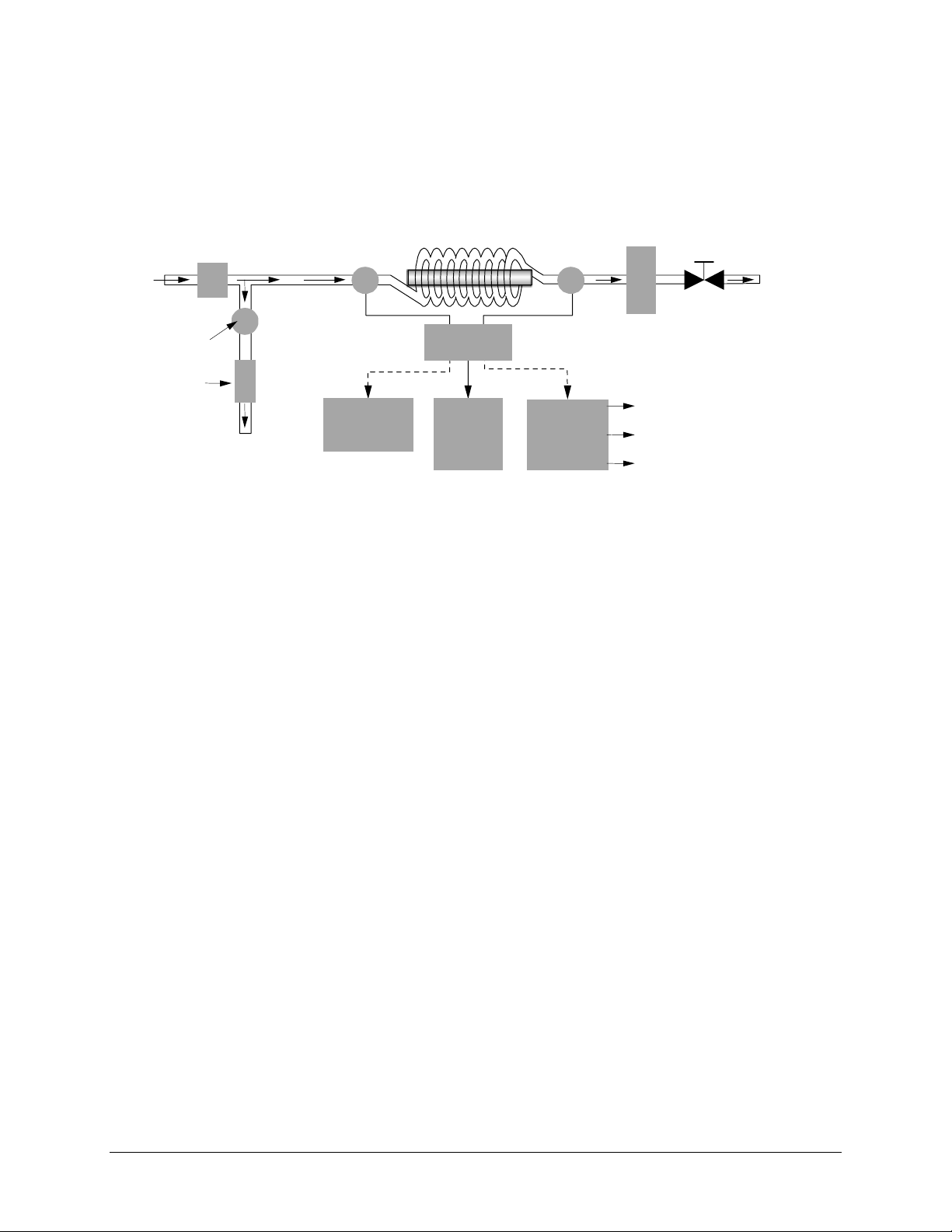
PRINCIPLE OF OPERATION
The Thornton 550 TOC Analyzer measures Total Organic Carbon in pure and ultrapure
water based on differential conductivity. This difference in conductivity is used to
determine the amount of organic carbon present.
Sample
Sample
Inlet
Inlet
Pressure
Control Valve
Conductivit
Sensor (1)
UV Oxidation
Conductivit
Sensor (2)
Flo
Meter
Flo
Control Valve
Oxidized
Sample
Outlet
Resistivit
Sensor (3)
Flow Orifice
By-pass
Sample Outlet
CPU
Printer
(Optional)
LCD
Displa
4-20 mA
nalo
Output
Terminal
TOC
Temperature
Resistivit
The sample water enters the analyzer and passes through a pressure regulator, which
controls sample pressure to downstream components. Here the sample splits into two
flow paths, where a portion of the flow is directed to the by-pass streamline, where
resistivity/conductivity and temperature are measured via Sensor (3). These values are
represented on the LCD display.
The other portion of the sample is directed through a second conductivity sensor, (1),
measuring the sample conductivity prior to oxidation. Next, the sample enters the
oxidation chamber. As the sample moves through the oxidation chamber, it is subjected
to high intensity ultraviolet radiation at 185 nm, effectively oxidizing the sample to CO2.
After oxidation, the sample passes through a third conductivity sensor, (2), where the
conductivity and temperature are measured again to determine the level of Total
Organic Carbon (TOC).
The microprocessor of the Thornton 550 TOC Analyzer uses the measured values of
initial (1) and final (2) conductivity and temperature to determine the change in
compensated conductivity, which is related to the concentration of organic impurity in
the incoming water stream.
The measurement and sample flow are continuous; therefore, measurement update
time is minimized, providing rapid response to any system disturbances.
The oxidized sample stream passes through a flow meter, which has a fine flow-control
adjustment, and then through the OXIDIZED SAMPLE OUTLET port. This effluent may
be sent to waste or recycled. The operating flow rate is typically 20 ml/min, resulting in
residence time in the oxidation chamber of less then one minute. The conductivity
2 GETTING STARTED

measurements are continuous; therefore, response time is directly related to the
residence time of the sample in the oxidation chamber.
Values of TOC, resistivity (or alternatively conductivity or uncompensated conductivity),
and temperature are displayed on the LCD screen of the instrument. These values can
also be printed or sent to a computer through RS-232 serial interface ports on the back
panel of the instrument at a user-selectable time interval. The last 255 sets of values
are stored in memory at the same time interval for viewing on the screen, or a
designated number of these data lines can be printed on a demand basis. Other outputs
include a continuous 4-20mA self-powered analog output signal and two configurable
potential-free alarm contacts. Refer to the specifications in the back of this manual for
details regarding these outputs
GETTING STARTED 3
CHAPTER 2: INSTALLATION / SET-UP
LOCATION
The Thornton 550 TOC Analyzer is to be installed in a dry environment with a relative
humidity <80% (non-condensing) and with ambient temperature between 5 and 40°C
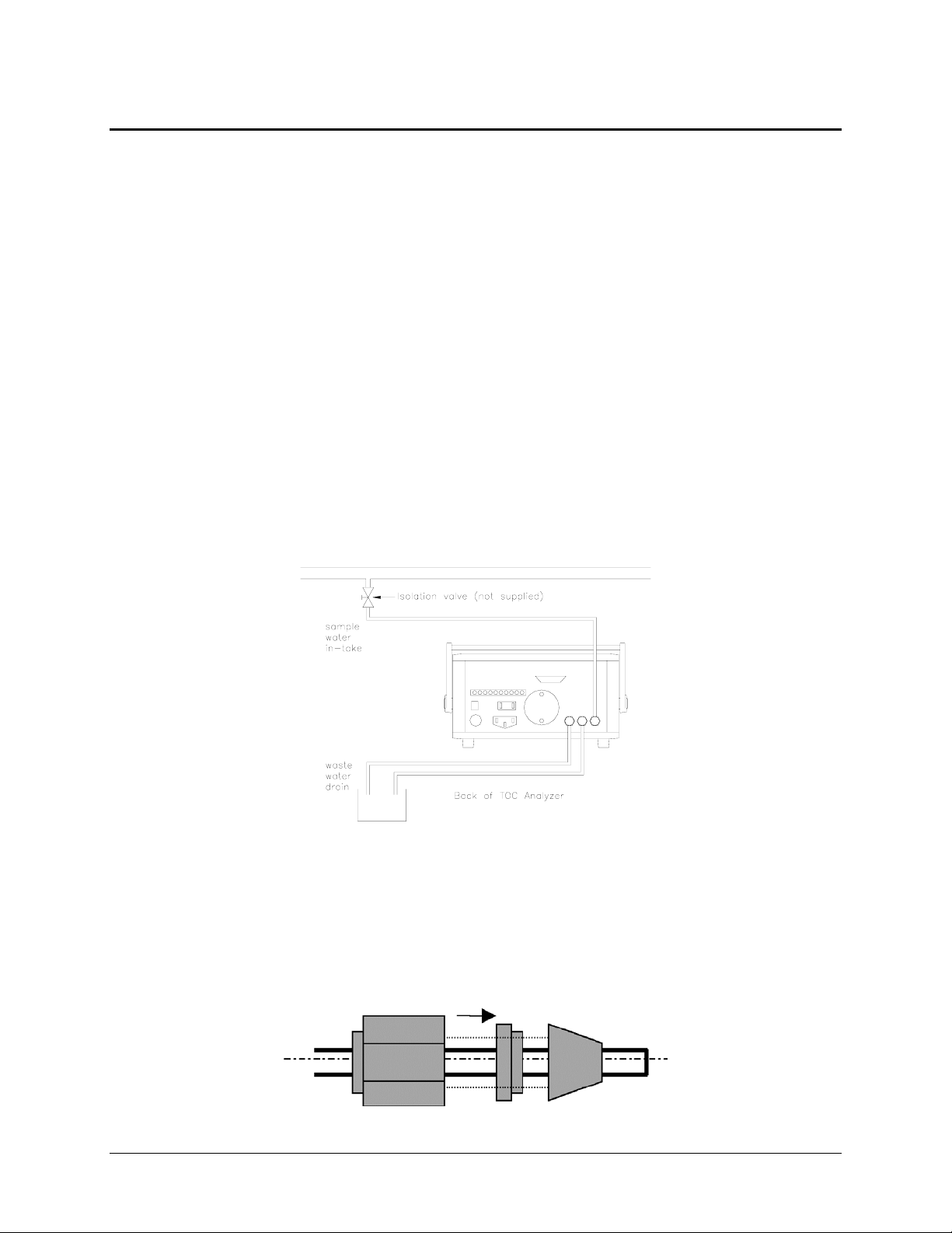
(41 to 104°F), on a flat, horizontal surface. The sample inlet line should be fitted with an
isolation valve. The OXIDIZED SAMPLE OUTLET and BYPASS SAMPLE OUTLET
tubes are led to waste (or a water reclaim system) at atmospheric pressure without any
obstructions in the tubing.
ELECTRICAL CONNECTIONS
A power outlet must be available within 3 ft. (1 m) when using the 3-pronged power cord
supplied with the analyzer. An adapter for the power cord may be necessary for outlets
of different configurations, depending on the country in which the unit is installed. The
unit requires a power source between 100 and 240 VAC at either 50 or 60 Hz.
Maximum power consumption is 50 W (with optional printer installed).
SAMPLE TUBING CONNECTIONS
Three pieces of 2.5 m (8 ft) tubing are supplied with the unit. Two pieces are relatively
clear and the third (PFA or similar Teflon® material) is opaque. The Teflon® tubing is
used for connection from the sample water line to the SAMPLE INLET port on the back
panel of the Analyzer. Hardware is to be assembled on the tubing as shown below for
connection of the tubing to its port.
4 INSTALLATION / SET-UP

The tubing can be shortened to your application. Shorter tubing provides faster
response time. Sample water pressure must be a least 0,5 bar (7.0 psi) but not greater
than 7 bar (100 psi). A pressure regulator, located inside the Analyzer, protects the
spiral quartz tube from damage by excessive inlet pressure.
The pieces of clear tubing are to be connected from the BYPASS OUT and from the
OXIDIZED OUT ports to the user’s drain at atmospheric pressure, without bends or
kinks in the lines. Likewise, these two pieces of tubing can be shortened, although this
will have no effect on performance.
ANALOG OUTPUT
The two terminal connections on the left-hand side of the terminal strip on the back
panel can be used for a self-powered 4-20 mA output. This ouput can be configured for
remote use of TOC (most common), resistivity, or temperature signal. The maximum
load resistance is 500 ohm.
ALARMS
Two sets of alarm connections, Normally Open, Normally Closed and common, are
provided on the same terminal strip. Each alarm can be independently configured as
either NO (Normally Open) or NC (Normally Closed).
ALARM 1 ALARM 2
NO1 COM1 NC1 NO2 COM2 NC2
Each alarm output is driven by a SPDT relay rated at 0.4A @ 120 VAC or 2.0A @
30 VDC. See CHAPTER 3: CONFIGURATION for more information.
USER INTERFACE/PRINTER
Two RS232 connections are available and located on the rear-panel of the analyzer.
PRINTER
The connection labeled ‘PRINTER’ is a 9-pin, male or female, sub-D connection for
connecting an optional printer, with serial interface. The printer port can also be
connected to a computer having a serial interface.
Communication specifications for this port: 9600 baud; 1 stop bit; no parity; 8-bit data.
Software such as hyperterminal, a standard windows based software, may be utilized to
collect data with a PC.
Mettler-Toledo Thornton, Inc. supplies a small format thermal printer as an optional
accessory. A straight-through 9 pin, male or female, sub-D cable is provided with this
printer. Configuration (Dip switch settings) for this optional printer can be found in the
APPENDIX. An operation manual is also included with the printer. Power for this
printer is supplied by the 550 TOC ANALYZER (6 VDC). The power connection is
made at the rear of the analyzer.
INSTALLATION / SET-UP 5

RS232C
The connection labeled “RS232C’ is also a 9-pin sub-D connection for connecting a
computer using a serial interface. This port, used in conjunction with a computer having
serial interface capability, can be used as an alternate means to collect the operating
data from the analyzer. The Computer must have the means to collect this serial data,
which will be transmitted in the same format as it is transmitted to the optional printer.
The following communication specifications apply.
Communication specifications for this port: 2400 baud; 1 stop bit; no parity; 8-bit data.
Software such as HyperTerminal, a standard Windows® based software, may be
utilized to collect data with a PC.
START-UP
After all the tubing has been connected, sample water can flow through the unit. Open
the user-furnished sample isolation valve. Observe the flow rate from the flow meter on
the front panel of the Thornton 550 TOC Analyzer. Adjust the flow rate to the maximum
setting by means of the flow adjustment knob, located at the top of the flow meter. If not
already installed, connect the power cord to the socket located at the rear of the
Thornton 550 TOC analyzer and insure the other end is connected to a suitable power
source. Press the power button located at the rear of the analyzer to ON. This will
enable the front display screen showing the Thornton name, model # and software
version of the analyzer.
At this time, the analyzer should be rinsing with sample water to remove any impurity
present on the sensors or in the system tubing and components. This will also help
remove air bubbles, as any entrained air can cause errors in readings. Upon initial
installation and start-up, it is recommended that the analyzer be rinsed for a minimum of
4 hours to 12 hours. The analyzer can be used immediately, but depending on water
quality, time may be needed for readings to stabilize.
If the desired flow rate is not achievable, the internal pressure regulator may have to be
adjusted. With the power to the Analyzer turned off and the power cord disconnected
from the power source, remove the top cover. Depress each of the four buttons on
opposite sides, just under the lip of the top cover, so that each of the 4 strips on top lifts
open. The exposed, large Phillips
cover can be removed.
Note: There is a proper front and back to the cover. The bottom sides of the cover
have male and female grooves, respectively. When replacing the cover, make sure the
female groove on the cover lines up with the male mating surface on the housing on
one side; the genders will be reversed on the other side.
The pressure regulator can be seen toward the back left of the analyzer. First, rotate the
flow adjustment knob on the front of the analyzer counterclockwise, to the full open
position. Then, on the internal pressure regulator, rotate the knob on the top of the
regulator to adjust the pressure until the flow reads 100 ml/min.
®
-head screws can now be loosened so that the top
6 INSTALLATION / SET-UP

After rinsing, use the flow adjustment knob to set the flow to 20 ml/min.
CAUTION: Even if no pressure adjustment is required (which is the usual case); the
cover should be removed so that the analyzer can be checked for water leaks, as any
leak could be a source of error in the readings and also could lead to damage or failure
of the unit.
When all of these installation steps have been completed, replace the top cover, plug in
the power cord, and press the power button, at the rear of the analyzer, to ON.
INSTALLATION / SET-UP 7
p
CHAPTER 3: CONFIGURATION
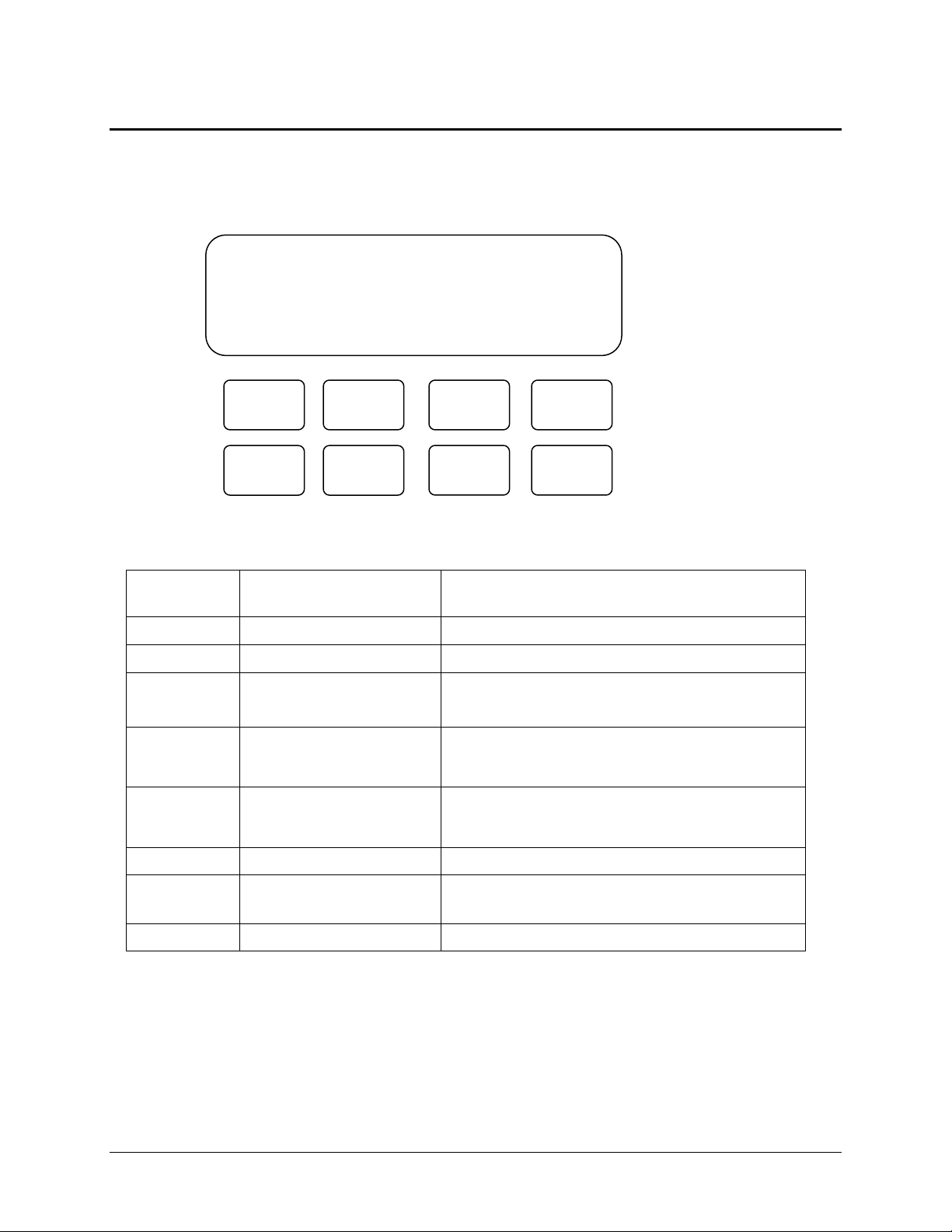
The unit can be configured before or after installation as described in Chapter 2. When
the unit is first powered, the following “TITLE” display will be seen.
Symbol Name Major function
THORNTON
550 TOC Analyzer
Ver 1. XX
Esc
Next
Up
Down
Menus
Enter
Save
Start/
Sto
Menus Menu key Enter menu display
Save Save key Save changes
Start/ Stop Start measurement
Stop measurement
Up
Up key Increase number / move the cursor or
Down
Down key Decrease number / move the cursor or
Start measuring TOC
Stop measuring TOC
check mark (*)
check mark (*)
Enter Enter key Enter or exit from a menu line
Esc Escape key Escape from the current menu level to the
previous menu level
Next Next key Scroll the menu displays / move cursor
8 CONFIGURATION

The 550 is available in three different models, the standard unit, known simply as the
550 will display the title as shown above. The High Temperature version will show the
model number 550-HT and the enhanced resolution version will display the model
number 550-SX. The current software version installed is also displayed below the
model number.
This title screen will also display two other status indicators, when programmed to do
so. In the bottom right-hand corner the word “Demo” will flash, indicating that the
analyzer has been placed into demonstration mode. Also, it may flash “Auto Start ON,”
when the analyzer has been programmed to do so.
As shown above the front panel of the 550 provides (8) eight keys for manipulation of
the unit’s set-up, configuration, and maintenance menus. See KEYPAD/DISPLAY
FUNCTIONS Table in the APPENDIX for a detailed description of the function of each
key.
USER SETUP AND CONFIGURATION MENUS
When the unit is in Standby mode, the first level of menu displays can be accessed by
pushing the MENUS key. This array of menus will be used to setup or change the
configuration of the 550 TOC Analyzer for normal operation. The 550 software contains
a lockout function that when enabled allows configuration changes only if a password is
entered. The screens should appear as follows:
NOTE: If lockout is enabled (‘Lockout ON’), when pushing the MENUS key from the
Title Screen, the next screen will ask for Password Input. The factory default for this
password is ‘0000’, (all zeros). The password can be configured for a personalized
four-digit password from the Maintenance Menus. Otherwise pushing the Menus key
from the Title screen will display the main menus.
Push MENUS key to enter the password screen as shown below:
Push ENTER Key to view the 1
THORNTON
550 TOC ANALYZER
Ver 1.XX
PASS WORD INPUT
PASS WORD 0000
(Lock Out ON)
1.*ALARM – 1 MODE
2. ALARM – 2 MODE
3. ALARM VALUE
4. ALARM DELAY
st
page of the main menus as shown here:
CONFIGURATION 9

Push the NEXT key to view the 2nd page of the main menus as shown here:
5. *PRINT SETUP
6. ANALOG SETUP
7. ANALOG CALIB
8. UV TIME
Push the NEXT key again to see the 3rd main menus as shown here:
9. *CALENDAR SETUP
10. SYSTEM CONFIG 1
11. SYSTEM CONFIG 2
12. MAINTENANCE
The above menus are the (12) twelve main menus used for set-up, configuration and
maintenance of the 550 TOC Analyzer
CALENDAR
First, set the Calendar by pushing the MENUS key. Once at the 1st menu screen, push
the NEXT key until you reach the 3rd menus screen shown below:
This is a 24-hour clock. Press ENTER to access the yy/mm/dd fields. Use the NEXT
key to move the cursor to the number to be changed. Use the UP/DOWN keys to
change the number. After adjusting the date, press ENTER and move the * with the
DOWN key to the time. Adjust in the same manner. “SET OK” will flash. Press ESC to
return to the previous menu screen.
9. *CALENDAR SETUP
10. SYSTEM CONFIG 1
11. SYSTEM CONFIG 2
12. MAINTENANCE
If necessary move the * to 9. CALENDAR SETUP using the DOWN key.
Press ENTER.
Calendar Setup
yy/mm/dd *2003/07/20
hh/mm/ss 11:20:35
Note: The calendar is backed up by a battery on the printed circuit board.
Confirm the time if the unit has not been powered for several weeks.
10 CONFIGURATION

Now that the general method of key/display is known, the remaining functions can be
easily performed. Refer to the Appendix for a table of KEY/DISPLAY FUNCTIONS and
the Operation Flow Charts.
SYSTEM NAME
Go to “10. System Config 1” (on 3rd page of main menus) by moving the asterisk with
the up/ and down keys, until it is on line 10.
Press ENTER.
Press ENTER to highlight the first digit and using the UP, DOWN and NEXT keys, the
Sys Name may be set at 0000 or it may be an abbreviated form of the serial number.
For example, for S/N 960012, the Sys Name would be 9612. This is arbitrary, and it
can be changed by the user.
9. CALENDAR SETUP
10. *SYSTEM CONFIG1
11. SYSTEM CONFIG 2
12. MAINTENANCE
SYSTEM CONFIG 1
Sys Name *0000
Print-T unit min.
Program Ver x.xx
OUTPUT SETUP
This section provides instruction for setup of the 550 outputs. If you are using this
Analyzer for measurement only, you may proceed to the AutoStart section of
configuration. Otherwise, configure outputs as described in the sections below.
ALARM SETUP, CODES, and SETPOINTS
The Thornton 550 has two independent relay alarms. Each can be configured for one
of the three measurement parameters on the display. Choose the parameter and set
point. The condition (NO or NC) for each relay is determined by the wiring terminals
selected (see INSTALLATION). Configuring the alarms requires the following
procedure. There is also a menu tree in Appendix B:
From the title screen press MENUS.
Move to 1. ALARM MODE-1 or 2. ALARM MODE-2.
Press ENTER to reach the following screen display for either alarm:
ALARM-1 MODE
ITEM = *ppb
RELAY = High On
HIST. = 00
CONFIGURATION 11

ALARM-X (1 OR 2) MODE CONFIGURATION
ITEM
Select output parameter ppb = TOC
Mohm = Resistivity
°C = Temperature of sample water
ERset = Error
None = no output
RELAY
Definition of relay activation
Low Off = Relay off at lower than set point
Low On = Relay on at lower than set point
High Off = Relay off at higher than set point
High On = Relay on at higher than set point
If Erset is selected in parameter, relay activation is automatically set to ON
HIST.
This sets the Hysteresis associated with the alarm set point. A value from 0 to
99 can be entered.
HIST. = XX (0 to 99)
PRINT SET-UP
If an optional printer is used, set up the printing of measurement data as follows:
In the MAIN Menus, 2nd screen Select: 5. Print Setup
Print Setup
Print Time = 0
History Wrt = OFF
Nr. Of Data = 0000
1 Sec
Print time is the interval between printing, in seconds, minutes or hours. This display
shows an interval of 1. To change this value, move the cursor to the appropriate digit
with the NEXT key; then UP or DOWN to change the value.
Ranges for print intervals are: 1-99 seconds, 1 - 99 minutes and 1-99 hours, all in
increments of 1 (sec., min or hr.). This same time also determines Trend Data display
(see OPERATION). To program the units of the Print Time and Trend Data, go to
10.System Configuration 1. Press Enter.
SYSTEM CONFIG 1
Sys Name 0000
Print-T unit *sec
Program Ver x.xx
Using the down key move the cursor to Print-T unit. Press enter. Using the up key
change the unit to sec, min, or hour. Press enter. Press save. Select yes by using the
Use of History Wrt and Nr. Of Data are
explained in OPERATION.
12 CONFIGURATION

up key. Press enter. Note: Changing Print-T unit will reset the print time to 01. Press
the esc key twice to return to the title screen.
ANALOG (4-20 mA) OUTPUT
In the MAIN menus, 2nd screen, Select: 6. 4-20 mA SETUP
The Output options are as follow:
In the above display, the 4-20 mA output is configured for TOC. The 4mA output
represents 0.0 ppb TOC, and 20 mA represents 100.0 ppb TOC. These limit values are
user selectable with values of 000.0 to 999.9.
ANALOG SETUP
Output = *ppb
4mA Lmt = 000.0
20mA Lmt = 100.0
ppb TOC (ppb)
Mohm Resistivity (Mohm-cm)
°C Temperature (°C)
Hold Holds current value (Used for 4-20 mA calibration)
Not Select Analog signal configured, output not used
None No configuration, output not used
AUTO START
In the MAIN Menus, Refer to 11. SYSTEM CONFIG 2:
Press ENTER.
When AUTO START is set to OFF, the operator must push START to initiate the
measuring process. When it is set to ON, the measurement process begins any time
the unit goes from the unpowered to the powered state. (This could be the result of the
operator switching the power ON, or from restoration of power after an outage.) It is
recommended that this be left OFF for initial operation in a particular application. To
change the status insure the asterisk is in front of the OFF on the AUTO START line,
press the ENTER key, and use UP/DOWN keys to toggle OFF/ON. Press SAVE to write
to memory.
9. CALENDAR SETUP
10. SYSTEM CONFIG1
11. *SYSTEM CONFIG2
12. MAINTENANCE
SYSTEM CONFIG 2
Auto Start *OFF
Print SYS Conf. OFF
History Clear OFF
CONFIGURATION 13
 Loading...