

Ready Access 275 DP Service Manual

Pass
-
Thru Window
Model 275
Manual/Self Closing,
MOER (Manual Open/Electronic Release)
Fully Automatic Electric
Installation instructions also include Model 275 LPHV , 275 DP and Model 375 Series
&


TABLE OF CONTENT
Topic Page
Disclaimer 4
Serial Number Identification 4
Introduction 5
Product Information
Description 5
Warranty 6
Specifications 7
Dimensions 7
Safety Information 8
Installation Procedures 8
Tools needed 8
Materials Needed 8
Physical Installation 9
Electrical Installation 12
Initial Operations and Testing 14
Electric Installation (MOER) 15
Adjustments and Calibrations 16
Electric Installation – Electric Eye (Model 275 – 30” High) 18
Operational Procedures
Modes of Operation 22
Operations 22
Control Identification, Explanation and Function 22
Maintenance
Maintenance Schedule 23
Daily, Monthly, Yearly 23
Service Controls 24
Troubleshooting Guide (Cause and Effect) 25
Parts Lists
Complete Parts List (Description/Part Number) 29
Drawings - Exploded Views / Schematics 33
3
DISCLAIMER
READY ACCESS DISCLAIMS ANY LIABILITY FOR ANY DAMAGE OR HARM
CAUSED TO THE 275 DRIVE-THRU WINDOW, IT’S OPERATOR OR ANY OTHER
EQUIPMENT HOWEVER CAUSED IF THE 275 DRIVE-THRU WINDOW IS REPAIRED
OR SERVICED BY ANYONE OTHER THAN AN AUTHORIZED SERVICE ENGINEER
OR CONTRARY TO THE MANUFACTURERS WRITTEN INSTRUCTION CONTAINED
HEREIN.
THIS MANUAL IS INTENDED FOR USE BY THE IN-HOUSE OR AUTHORIZED FIELD
SERVICE ENGINEERS AND SALES REPRESENTATIVES
The manufacturer maintains the right to update, add or issue a new service manual at any time without
notice, thereby rendering all previous issues obsolete.
Please write the Serial Number and Installation Date for your drive-thru window in the spaces provided.
Serial Number
Date of Installation
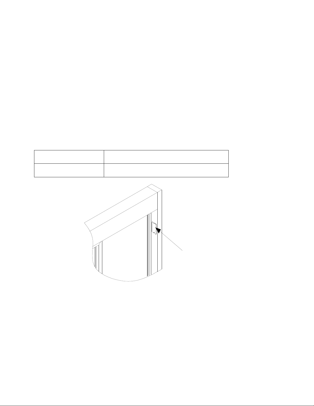
The serial number
nameplate is located
on the post
CONTACT INFORMATION
FOR SALES AND SERVICE CONTACT
Ready Access Tel: 630-876-7766
1815 Arthur Drive Tel: 800-621-5045
West Chicago, Illinois 60185 Fax: 630-876-7767
Email: ready@ready-access.com Website: www.ready-access.com
4

INTRODUCTION
The Ready Access window is quality designed to give you years of reliable, trouble-free service.
Each window is shipped pre-assembled, fully glazed and ready for installation. All Ready
Access windows are thoroughly tested prior to shipping.
The 275 Single Panel Slider Window is the perfect enhancement to the drive-thru concept,
offering unobstructed views of customer and crew.
The model 275 drive-up window comes in four versions, manual, self-closing, electric and
M.O.E.R. (Manual Open Electronic Release). The electric version is fully automatic with a
manual override in case of a power outage. The door will open and close by stepping into and
out of the light beam sensor, the electric version meets health code requirements.
to assist the window manually when in automatic mode, damage can occur to internal parts.
Do not attempt
The Self-Closing and M.O.E.R. versions also meet health code requirements for self closing.
You manually open the windows and gravity closes them.
This attractive and economical window is ideal for a drive-thru or walk up application. The large
service opening is suitable for both large and small operations. (See Chart on Page 6)
PRODUCT INFORMATION
• Manual/Self Closing or Electric Openings
The 275 Single Panel Slider keeps building costs down by offering the window in a manual/self
closing operating style. Or for those who experience heavier traffic, an electric operating style is
also available. Both models meet health department requirements for self-closing units.
• Ease of Operation
In a Manual/Self Closing operation, the inside attendant pulls the door handle, to open the door
and once the door is released gravity will close the window. The MOER operation opens the
same as manual and self close, however a magnet catches the door, once the attendant steps
out of the beam on the presence sensor the magnet releases and the door will close. With a fully
automated operation, the operator simply steps into the presence sensor and the movable
window panel slides open. When the operator steps out of the presence sensor, the movable
window panel automatically closes. The range for the presence sensor is adjustable to specific
customer needs.
• Quality Construction
Anodized aluminum extrusions, stainless steel and 1/4" tempered glass combine to give you an
attractive window that not only enhances building exteriors, but will not rust, pit or weather. Track
free bottom sill provides for a contaminant free surface.
• Triple Security Locks
The 275 Single Panel Slider automatically locks each time the window closes, providing security
when the window is left unattended. When the drive-thru is closed, manual security locks help
prevent outside entry. There are two security locks for night use, the thumb-turn latch and the
night security bar.
5

• Fully Assembled, Ready to Install
Ready Access windows are shipped completely pre-assembled and fully glazed for lower
installation costs. Normal installation takes less than two hours.
• Three to Five Day Shipping
Ready Access will ship any standard window order in 3 to 5 days from receipt of order. We offer
custom windows in our 275 line; however lead times can vary from 3-6 weeks.
• Warranty and Service Support
Your Ready Access window comes with a one year limited warranty on parts and labor provided
by a worldwide service organization.
STANDARD OPTIONS
• The 275 Single Panel Slider is available in statuary bronze or clear anodized aluminum.
• 4 standard window dimensions available: (See Chart on Page # 6)
• A retrofit kit is available for the 47 ½” wide 275 Single Panel Slider that easily upgrades the
window from a manual operation to a Manual Open/Electronic Release or fully automatic
operation.
• An inside/outside stainless steel shelf is also available.
CUSTOM OPTIONS
• Custom sizes are available in both manual and self closing operation. Custom heights are
available in electric operation.
• Tinted glass is available upon request.
• Powder coat painting (Tiger Drylac) is available in a wide range of colors.
WARRANTY:
Ready Access will only accept responsibility for manufacturing defects in the
product’s construction and/or materials.
Adjustments required during installation are the responsibility of the installer or
contractor and will not be covered under warranty.
Problems caused by improper installation are the responsibility of the installer or
contractor and will not be covered under warranty.
6
Model
Number
275
110/120 VAC
275
110/120 VAC
275
110/120 VAC
275
(SC)
Dimensions
In Inches
W x H x D
47½ x 43½ x 4
47½ x 35¾ x 4
47½ x 30 x 4
35 ¾ x 35¾ x 4
West Coast Window
Dimensions
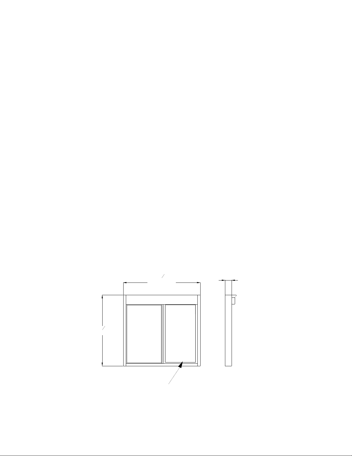
SPECIFICATIONS AND PERFORMANCE
Unit
Voltage
USA International
60Hz
60Hz
60Hz
N/A
Opening Size
19 ¼” x 35”
19 ¼” x 27 ¼”
19 ¼” x 21 ½”
13 ⅝” x 27 ¼”
15 ⅝” x 27 ¼”
220/240 VAC
50/60Hz
220/240 VAC
50/60Hz
220/240 VAC
50/60Hz
N/A
Service
W x H
[1206.50mm]
47
Actual
Unit
Amps
15 A (US)
8 A (Int’l)
15 A (US)
8 A (Int’l)
15 A (US)
8 A (Int’l)
N/A
Glazing Rough
Opening Size
47 ¾” x 43 ¾”
1213mm x 1111mm
47 ¾” x 36”
1213mm x 914mm
47 ¾” x 30 ¼”
1213mm x 768mm
36” x 36”
914mm x 914mm
1
"
2
Dimensions
In Inches
W X H x D
47½ x 43½ x 4
47½ x 35¾ x 4
47½ x 30 x 4
35 ¾ x 35¾ x 4
Masonry Rough
W x H
1219mm x 1118mm
1219mm x 921mm
1219mm x 775mm
921mm x 921mm
4"
[101.60mm]
Weight
In Shipping
Carton
95 lbs
87 lbs
80 lbs
80 lbs
Opening Size
W x H
48” x 44”
48” x 36 ¼”
48” x 30 ½”
36 ¼” x 36 ¼”
1
43
"
2
[1104.90mm]
SEE CHART FOR OPENING SIZE
Figure 1
7

Safety Information
WARNING: To avoid the risk of fire, Electric Shock or injury to persons, observe the following:
1. Before servicing or cleaning the unit, switch the power off at the mechanical switch near the unit
(Installed by an Electrician) or the electrical entry service panel/circuit breaker. (Load Center)
• OSHA LOCK OUT – TAG OUT procedures are to be observed to prevent power from being
switched on accidentally.
2. Any Installation and / or Electrical work must be done by QUALIFIED persons in accordance with
all applicable codes / standards and manufacturers recommendations and specifications.
3. DO NOT insert fingers and / or foreign objects into the Drive-Thru Window.
DO NOT block or tamper with the unit in any manner while it is in operation.
4. This product must not be used in Potentially Dangerous locations such as Flammable, Explosive
Chemical – laden environment.
Installation Procedures
Tools required to perform the installation
• Electric Drill
• Metal Drill bits –
⅛” (3mm)
¼” (6mm)
½” (13mm)
1” (25mm)
• Screwdrivers – Slotted and Phillips
• Hacksaw
• Jack / Utility Knife
• Flat File – Coarse
• Caulking gun
• ¼” Nut Driver
Materials required for installation
• Window framing, architect specified and installed in building.
(Ready Access recommended material is ⅛“ (3mm) x 1 ¾” (44.5mm) x 4” (102mm) hollow
aluminum tubing or glazing channel)
• Electrical Tape
• Wire Nuts
• Caulking – silicone (Color specific to the color of window)
• Connectors for conduit as required
• Shingle type shims – as required to level and plum the window
• Extension Cord
• Masonry drill bit –
¼” (6mm)
1” (25mm)
1
½” (38mm)
• Masonry Hole Saw – 1” (25mm)
• Channel Lock Pliers
• Tape Measurer
• Wire Cutter
• Step Ladder
• Level
8
Physical Installation
Before you begin installing your Ready Access Drive-Thru Window, you must determine what type of installation
will be required. Example: Wood Framing, Masonry Framing, etc.
Please refer to the details below and pick which one best fit your application.
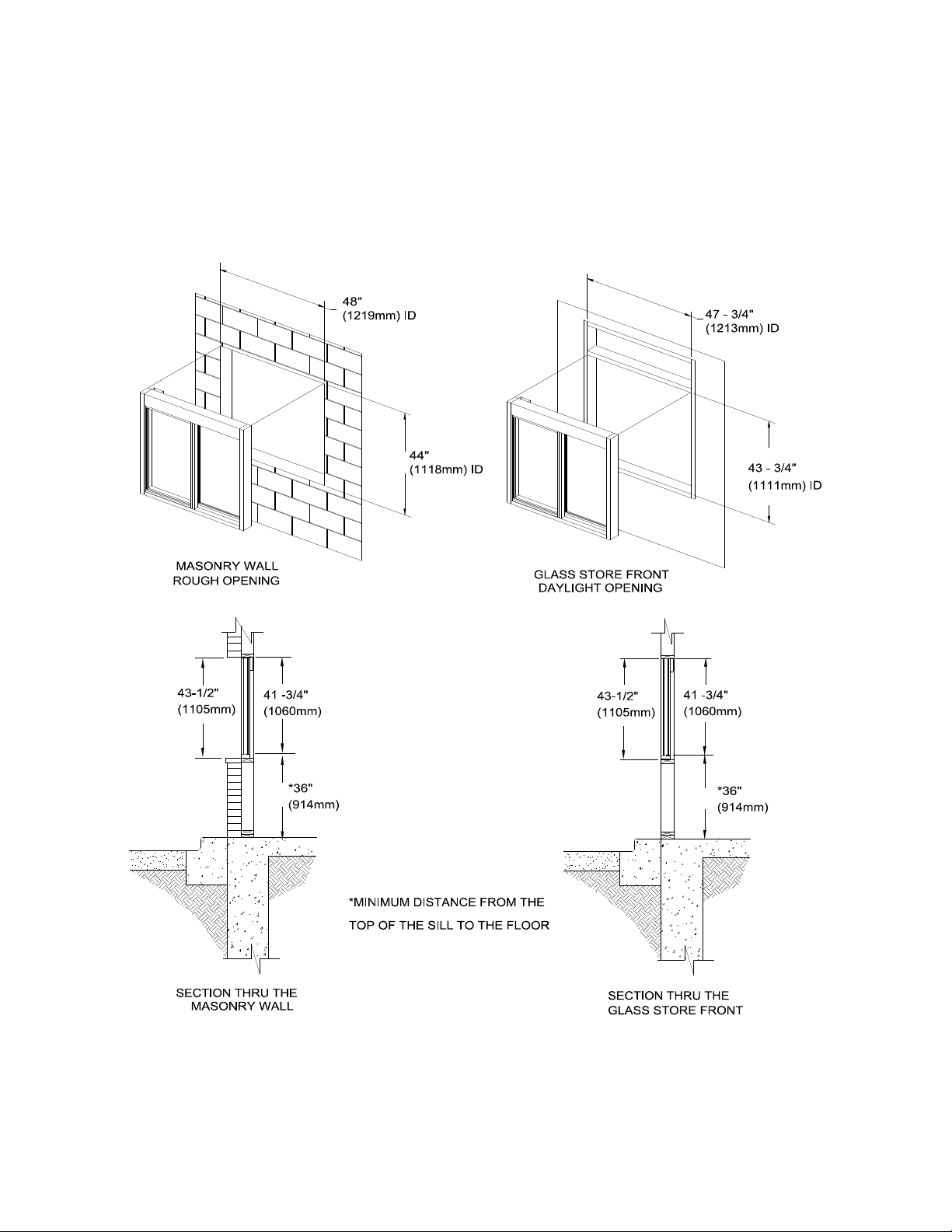
See Chart previous pages for Masonry and Glazing Rough Opening Sizes
FIGURE 2
9
WARNING:
TWO PEOPLE ARE REQUIRED FOR THE LIFTING AND
INSTALLATION OF THE WINDOW.
1. Check shipping carton for any shipping damage and remove window from the carton.
2. Check window for any shipping damage.
3. Confirm that the customer-supplied frame is made to accommodate the dimensions as illustrated
on page 10.
4. For the Fully Automatic – Electric units, confirm that AC power has been run and is ready for
connection to the window.
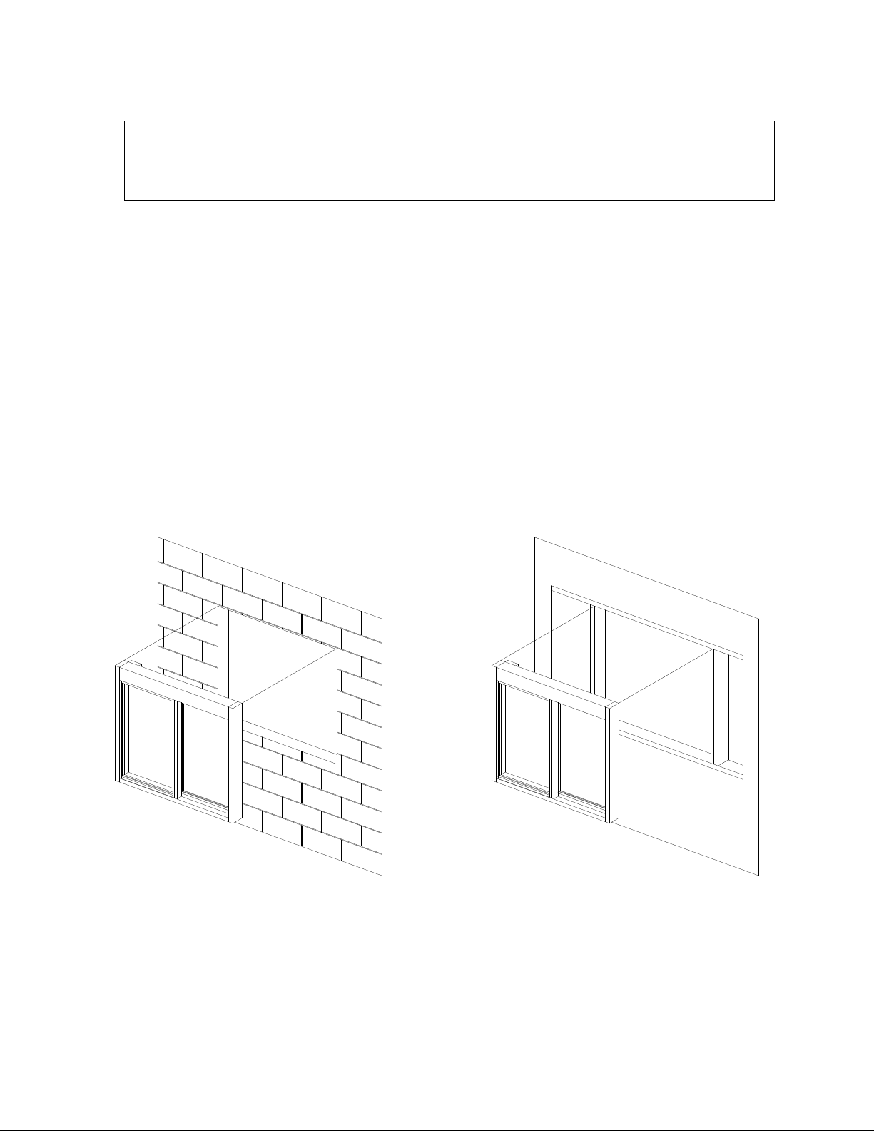
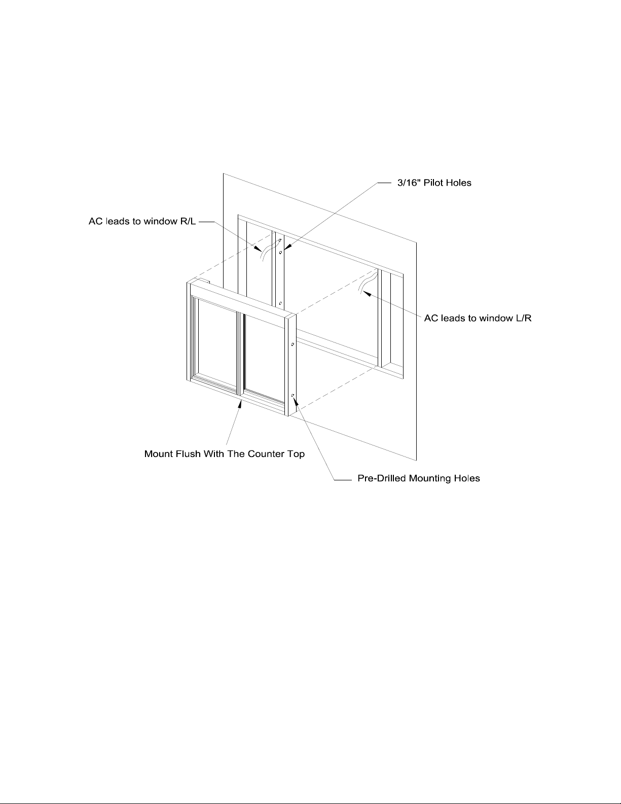
NOTE: There are two wall-mounting applications. The mounting space can be
surrounded either by sidelights (windows) or masonry. In both cases the upper
part of the window above the counter top (window sill) fits flush with the outside
of the wall. (See Figure 2) The illustrations will show the walls with the
sidelights, as this is the most common application. (Figure 3 and 4)
Figure 3 Figure 4
NOTE: If mounting the window in a masonry wall the window mounts flush with the
outside finishing of the building. Drill points are scribed directly into the masonry.
The outside edge of the mullion should be flush with the outside finishing of the
building. (See Figure 3 and 4)
10
5. Position the window and place it into the customer-supplied frame. As shown in Figure 3 and 4
6. With one person holding the window in place, level the window using the shim shingles as
needed.
7. Using the window mounting holes as a template, drill a quantity of 4 – 3/16” (5mm) diameter
holes for mounting. (See Figure 5)
Figure 5
8. Take the window back out and drill the mounting holes. Set the anchors as needed.
9. With one person holding the window in place from the outside, set the mounting screws.
10. When the window is fully secured, seal the outside of the window to the frame or building using
silicone caulk.
11
Electrical Installation (for electric operation)
All power must be connected and wired by a qualified electrician and must be in compliance with all
state and local codes.
The incoming AC power line must be connected to the wires in the duplex box located in the top header
(Per Standard electrical code.) The green “grounding” wire is to be attached to the frame of the unit.
WARNING: Use only 110/120VAC – 60Hz source with a dedicated 15Amp circuit.
International power: 220/240VAC – 50/60Hz with a dedicated 8amp branch circuit.
WARNING: This must be a dedicated circuit. Other electrical equipment must not share the same
line from the 15Amp circuit breaker.
WARNING: Turning off the front panel rocker switches does not remove the 110/120 volts of electrical
power form the unit
WARNING: To disconnect the power completely from this unit, turn OFF the mechanical switch near the
unit (Installed by an Electrician) or the electrical entry service panel/circuit breaker panel
(Load Center) for this unit.
• OSHA LOCK OUT – TAG OUT procedures are to be observed to prevent power from
being switched on accidentally.
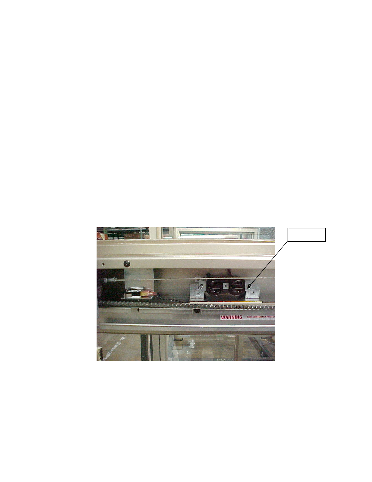
1. Remove the 4 screws holding on the slide channel cover.
2. Wire the AC source line to the duplex receptacle. (See Figure 6)
Receptacle
Figure 6 (Pre – 2003 models)
3. Connect the cable wire from the electric eye sensor.
4. Drill 4 - ¼” (6.5mm) holes using the masonry drill bit. (For Waist High Electric Eye Only)
5. Insert the plastic anchors and mount the brackets with the #10 or #12 screws. (For Waist High
Electric Eye Only)
6. Attach the sensor to the brackets and secure. (For Waist High Electric Eye Only)
7. Turn “ON” the power to the unit. (Load center circuit breaker and power switch on the “Control unit”.
8. Test window operations. See “Testing Procedures”.
12
For windows purchased after January 2003, follow these instructions.
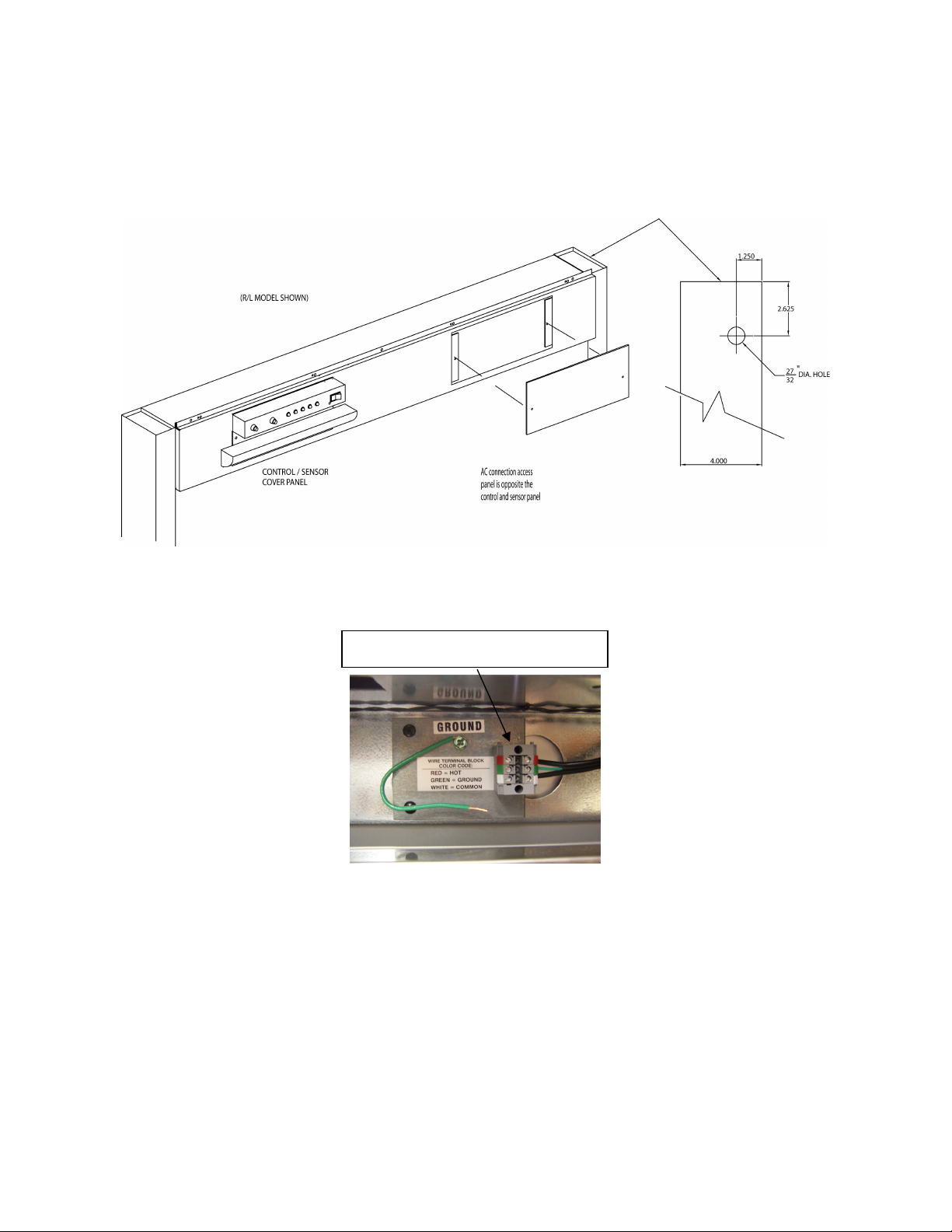
AC Terminal Block
1. Remove the 2 screws holding on the AC access panel. Do not remove the slide channel cover.
2. Electrician to drill hole in unit as shown. Install connector before running power line to unit.
Figure 6A (2003 and later models)
3. Wire the AC source line to the Terminal Block located in the header of the window.
NOTE: TO GROUND UNIT USE PIGTAIL BY TERMINAL BLOCK. THE LINE (L1) IS
INDICATED BY THE (RED) TAB AND THE RETURN (NEUTRAL) IS INDICATED BY
THE (WHITE) TAB. ON THE TERMINAL BLOCK FOR PIGTAIL LEADS COMING IN
TO TERMINAL BLOCK, WIRE TIES PROVIDED TO SECURE FREE END OF WIRE
LEADS TO PREVENT WIRES COMING IN CONTACT WITH MOVING PARTS.
NOTE: USE COPPER CONDUCTORS ONLY.
4. Turn “ON” the power to the unit. (Load center circuit breaker and power switch on the “Control
Panel”).
5. Test window operations. See “Testing Procedures”.
13

Initial Window Operation
Testing Procedures
Action Reaction
Turn the power “OFF” at the rocker switch
located on the controller unit.
Manually open and close the door several times.
Turn the power “ON” at the rocker switch located
on the controller unit.
Break the electric eye beam to open the door.
With the power “ON” break the electric eye beam
momentarily to open and close the door.
With the power “ON” press the “CLOSE DELAY”
button located on the controller unit once and
break the electric eye beam to open the door
With the power “ON” break the electric eye beam
momentarily to open and close the door. Insert an
object at least 4” (101.6mm) wide between the
door and frame as the door closes.
When the door is opening, the “MOTOR RUN”
lamp will illuminate green. When the door is
closing, “MOTOR RUN” lamp will illuminate red.
The “POWER” lamp must illuminate during both
operations. If neither of these lamps illuminate
during any of the processes, proceed to the
“Troubleshooting” section.
The door will open.
The door will open. They will remain in the open
position for either approximately 3.0 or 6.0
seconds before closing (Default Settings)
The door will open and the length of time that the
door remains open will toggle between 3.0 and
6.0 seconds before closing. (Default Settings)
The door will automatically reverse their action
(the door will open), when an object is caught
between or restricting the closing of the door.
14

Electrical Installation (For M.O.E.R. windows only)
All power must be connected and wired by a qualified electrician and must be in compliance with all
state and local codes.
WARNING: Use only 110/120VAC – 60Hz source with a dedicated minimum 15Amp circuit.
International power: 208/240VAC – 50/60Hz with a dedicated minimum 8Amp branch circuit.
WARNING: This must be a dedicated circuit. Other electrical equipment must not share the same line
from the minimum15Amp circuit breaker.
WARNING: Turning off the front panel rocker switches does not remove the 110/120 volts of electrical
power form the unit
WARNING: To disconnect the power completely from this unit, turn OFF the main switch near the unit
(Installed by an Electrician) or the electrical entry service panel/circuit breaker panel (Load
Center) for this unit.
• OSHA LOCK OUT – TAG OUT procedures are to be observed to prevent power from
being switched on accidentally.
1. The M.O.E.R. window simply plugs into a standard wall socket (Preferred a switched outlet).
2. Connect the cable wire from the electric eye / presence sensor.
3. Drill 4 - ¼” (6.5mm) holes using the masonry drill bit. (For Waist High Electric Eye Only)
4. Insert the plastic anchors and mount the brackets with the #10 or #12 screws. (For Waist High
Electric Eye Only)
5. Attach the sensor to the brackets and secure. (For Waist High Electric Eye Only)
6. Turn “ON” the power to the unit. (Load center circuit breaker and power switch on the wall if
available.)
7. Test window operations. See “Testing Procedures”.
Note: Do not hardwire or cut plug. This will void the warranty.
Initial Window Operation
Testing Procedures
Action Reaction
Turn the power “OFF” (M.O.E.R. ONLY) at the
main switch. (Electrician Installed)
Manually open and close the door several times.
Turn the power “ON” (M.O.E.R. ONLY) at the
main switch. (Electrician Installed)
Manually open the door
This will assure that the door is performing to
specification.
The M.O.E.R. window will perform as a standard
Self-Closing unit
The door should stay open until you step out of
the beam sensor.
Once you step out of the sensor range, the door
should close by itself.
15
 Loading...