

Page 1
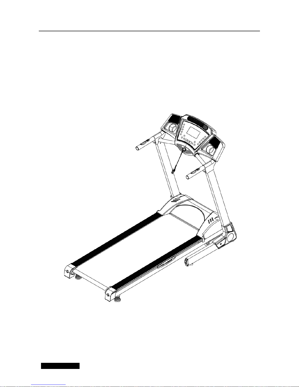
Installation Guide
Reach T-7
1
Page 2

Page 3
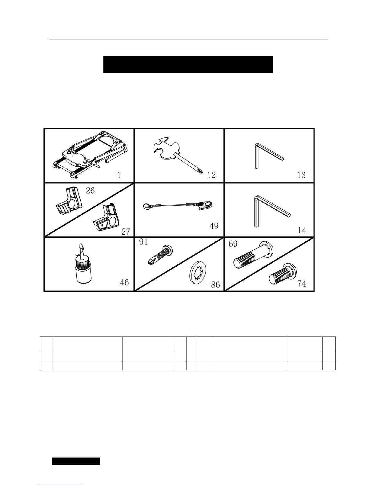
When you open the carton, you will have below spare parts:
SPARE PARTS LIST:
NO.
DISCRIPTION SPECIFICATION QTY
NO. DISCRIPTION
SPECIFICATI
ON
QTY
1
MAIN FRAME
1
46 Oil Bottle
1
12
Allen Wrench
S=13
\14\15mm 1
49
SAFETY KEY
1
ASSEMBLY INSTRUCTIONS
3
Page 4
13
5# Allen Wrench
5mm
1 69
Bolt
M8*45
2
14
6# Allen Wrench
6mm 1
74 Bolt M8*16 6
27
Basic right cover
1
86
Lock washer
8 8
26
Basic left cover
1
91 Bolt ST4.2*19 4
FIXING TOOLS:
5#Allen Wrench 5mm 1pcs
、
Notice: Do not get through power before complete assembly
ASSEMBLY STEPS
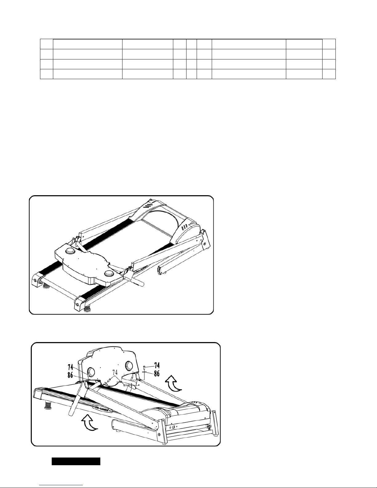
STEP 1
:
STEP 2
:
1 、 Open the carton and put the Main
Frame onto the level ground.
2. Holding the computer frame,Use the
5# Allen Wrench, drill through the Bolt
(74) to Lock Washer (86), then lock the
computer onto left & right upright
4
Page 5
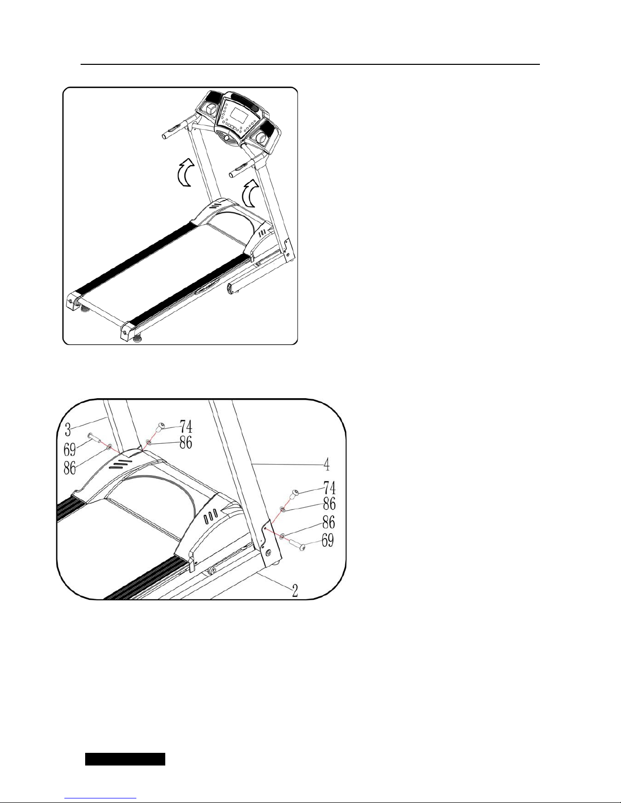
STEP 3
:
STEP 4
:
1.Push up the Computer and L& R
upright as the arrow position.
1. Use 5# Allen wrench(13), the Bolt
M8*45 (69), Lock washer(86)and to
fix the Right Upright Tube onto the
base.
2. Use 5# Allen wrench(13), use the
M8*16 bolt(74) and lock washer(86)
to fix the Right Upright Tube onto the
base.
3. Repeat for the Left Upright
Tube.
Notice: Support the upright with
hand, avoid falling down to have
any hurt.
5
Page 6
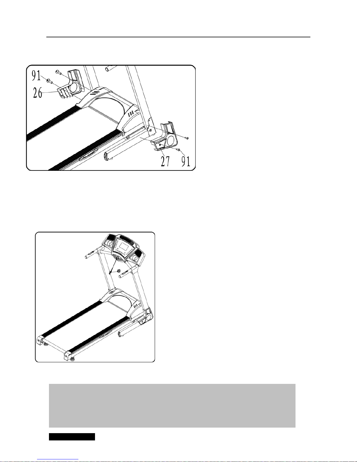
STEP 5
:
STEP6
:
1. Use ST4.2*19 Bolt (91), fix the base right
cover(27) on the Right upright group and
base.
2. Use ST4.2*19 Bolt(91), fix the base left
cover(26) on the Left upright group and
base.
1. Put safety key (49)on the its
place, turn on the power switch.
ATTENTION:Please confirm complete assembly as require above and lock the bolt. Do
the following operation after checking everything is OK. Before you use the treadmill,
please read the instruction carefully.
6
Page 7
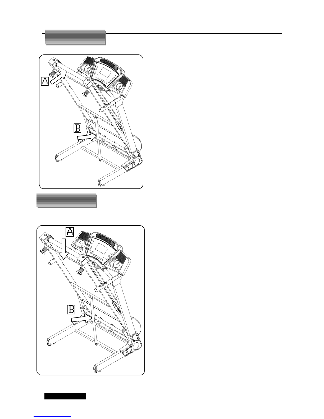
1、Support place A with hands, then pull
up the machine, till hearing the sound
that pin bar B is locked into the round
tube
1、Support place A with hands. Hold up
the machine slightly and kick the pin bar
then pull down the frame by hand and
let it down automatic till on the floor.
Pulling down:
Pulling up:
7
Page 8
Technical Parameter
BUILT UP
SIZE(mm)
1691*720*1315mm
POWER
As the rating label
showing
FOLDABLE
IZE(mm)
938*720*1525mm
Maximum output
power
As the rating label
showing
RUNNING
BOARD
SIZE(mm)
480*1300mm
SPEED RANGE
1-16KM/H
NET WEIGHT
64 KG
MAX USER
WEIGHT
120KG
1 LCD WINDOW
WITH BLUE
BACKGROUND
Speed, Time, Distance, Calories, Pulse
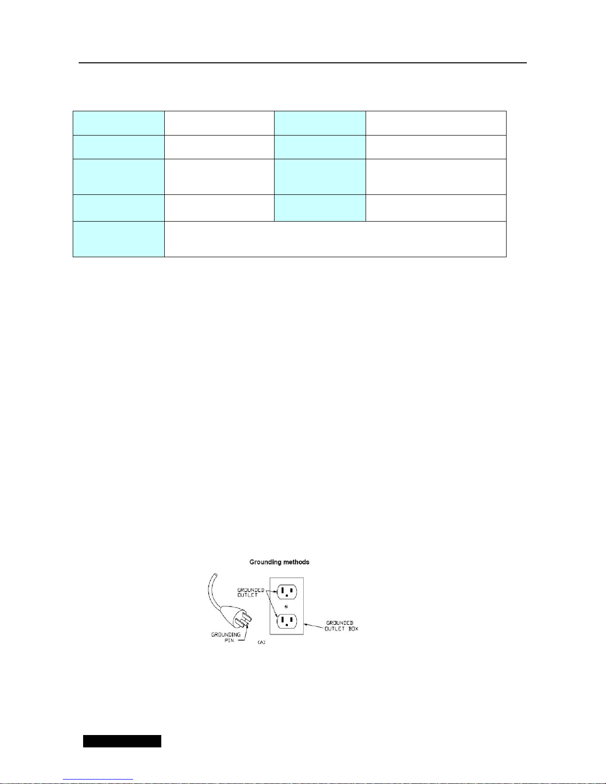
Grounding Methods
This product must be grounded. If it should malfunction or breakdown, grounding provides
a path of least resistance for electric current to reduce the risk of electric shock. This
product is equipped with a cord having an equipment-grounding conductor and a
grounding plug. The plug must be plugged into an appropriate outlet that is properly
installed and grounded in accordance with all local codes and ordinances.
DANGER – Improper connection of the equipment-grounding conductor can result in
a risk of electric shock. Check with a qualified electrician or serviceman if you are in doubt
as to whether the product is properly grounded. Do not modify the plug provided with the
product – if it will not fit the outlet, have a proper outlet installed by a qualified electrician.
This product is for use on a nominal 220-240-volt circuit and has a grounding plug that
looks like the plug illustrated in sketch A in following figure. Make that the product is
connected to an outlet having the same configuration as the plug. No adapter should be
used with this product
.( The below picture is just for reference)
8
Page 9
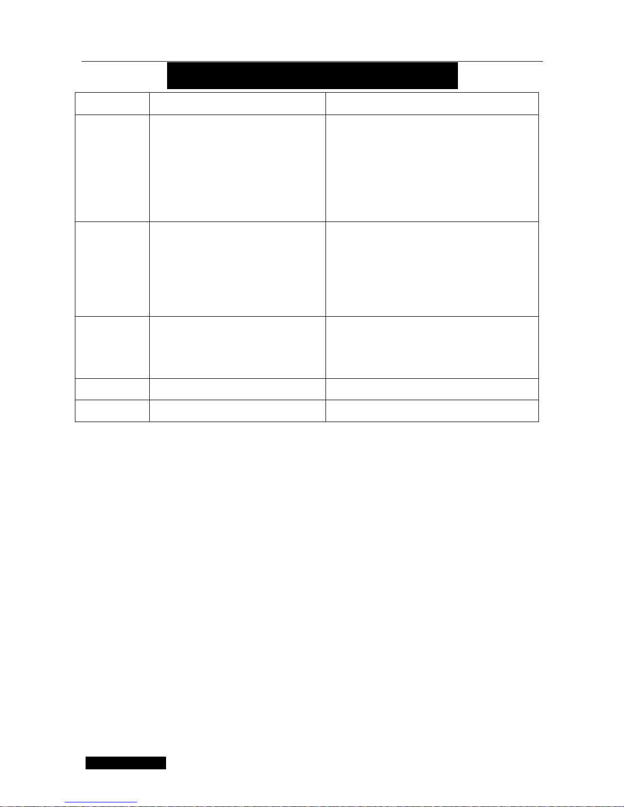
Fault Code Main reason Solution
E01 The wire from computer to bottom
control board didn’t connected well
1
.
Check the connection wire between
computer and control board was well
connected.
2 . Make sure the IC on the control board
was well inserted. If not re-insert.
3. Abnormal power supply in control board.
Please change a new control board.
E02 Protect the exploding
1
.
Bad contact with motor open circuit.
Please change a new motor or check the
connector.
2. Power tube was puncture. Please change
a new Power tube or control board.
E05 Overcurrent Protection
1. Overloaded
。
2 . Running board with heavy resistance.
Need to be oiled
3. Damage in Motor. Change a new motor.
E06 Control board self-checking
E08 EEPROM damage Change the control board
Calorie Computational formula
70.3×V(Km/h)×t(h)
It will take 70.3 calories per kilometers under condition that the incline is 0.
TROUBLE SHOOTING GUIDE
13
Page 10
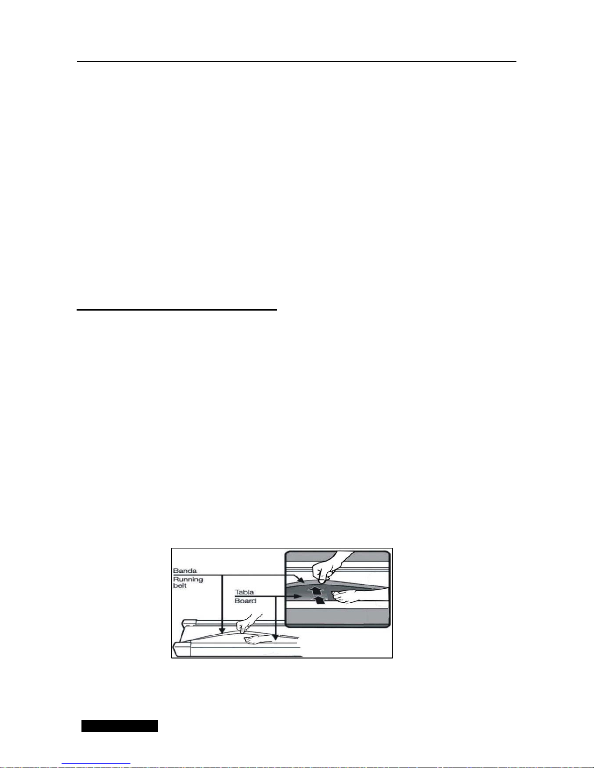
Running Belt Adjustment
Warning: ALWAYS UNPLUG THE TREADMILL FROM THE ELECTRICAL OUTLET BEFORE
CLEANING OR SERVICING THE UNIT.
Clean: General cleaning the unit will greatly prolong the treadmill.
Keep treadmill clean by dusting regularly. Be sure to clean the exposed part of the deck on either
side of the walking belt and also the side rails. This reduces the build up of foreign material
underneath the walking belt by wearing the clean running shoes.
Warning: Always unplug the treadmill from the electrical outlet before removing the motor
cover. At least once a year remove the motor cover and vacuum under the motor cover.
RUNNING BELT AND DECK LUBRICATION
This treadmill is equipped with a pre-lubricated, low maintenance deck system. The belt/ deck
friction may play a major role in the function and life of your treadmill, thus requiring periodic
lubrication. We recommend a periodic inspection of the deck. You need contact with our service
center if you find the damage of t he deck.
We recommend lubrication of the deck according to the following timetable:
Light user (less than 3 hours/ week) annually
Medium user (3-5 hours/ week) every six months
Heavy user (more than 5 hours/ week) every three months
We recommend that you buy the lubrication from our distributor or directly to our company.
Attention: Any repair need the professional technician.
14
Page 11
1. We suggest that you should switch off the power for 10 minutes after keep running 2 hours , so
that it’s good for maintain the treadmill.
2. For avoiding the slipping during running , the belt should be not too loose; for avoiding the more
abrasion between the roller and belt and maintain the machine’s good running ,the belt should be
not too tight. You can adjust the distance between deck and belt , the belt should be away from
the deck about 50-75mm on both sides.
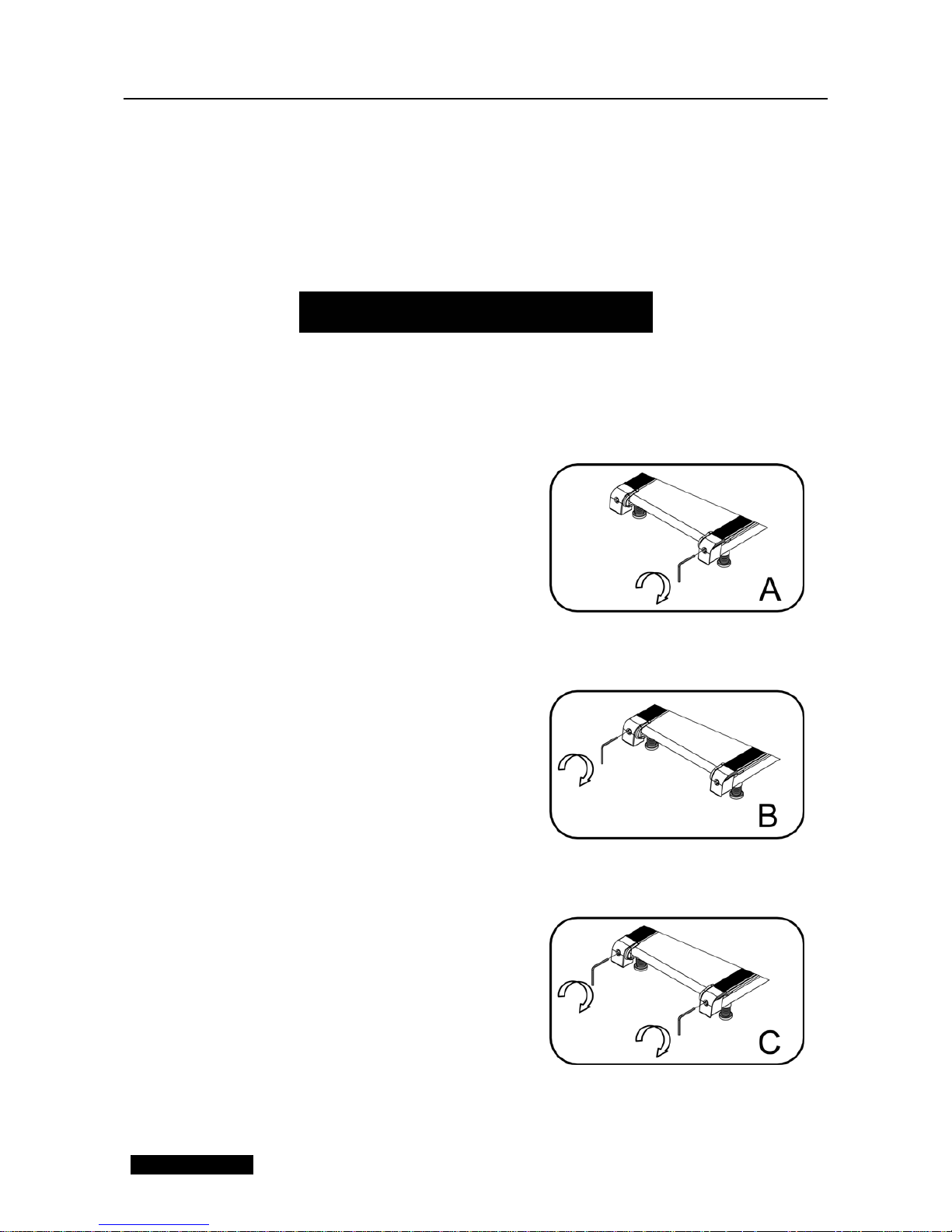
Place treadmill on a level surface. Run
Treadmill at approximately 6-8KM/H,
checking the running condition.
If the belt has drifted to the right, pull out
of the save clock and switch, turn the right
adjusting bolt 1/4 turn clockwise, then
start running until centering the belt. PIC A
If the belt has drifted to the left ,pull out of
the safety clock and switch, turn the left
adjusting bolt 1/4 turn clockwise ,then
start running until centering the belt .PIC B
Timely adjust the tightness of the belt ,for
the looseness after a period of time
running. Pull out of the safety clock and
switch , turn the left and right adjusting
bolt 1/4 turn clockwise ,then re-start
running, confirm the belt-tightness until
the belt be right tightness. PIC C
Center the running belt
15
Page 12
9
"
14
79
-
-y
....
13
22
12
44
_/
55 81
CJY"
51
83 --""-...
--·---56 75
57
V46
48
4
4 86
Page 13

NO.
1
DISCRIPTION
Main frame
SPECS QTY. 1 NO.
51
DISCRIPTION
Magnet ring
SPECS QTY.
1
2
Base frame
1
52
Switch
1 3 Right upright tube
1
53
Standard power line
1 4 Left upright tube
1
54
Overload Protector
1 5 Right Handrail tube
1
55
AC single wire
1 6 Incline frame bracket
1
56
Blue single wire
1
7
Motor bracket
1
57
Brown single wire
1
8
Running Board Strengthen
2
58
Power line buckle
1
Tube
9 Turning pipe
2 59
The annular convenient plug
2
10
Pipe
2
60
Screw
M10
4
11
Spring
2
61
Screw
M8
4
12
Allen Wrench
S=13、14、15
1
62
Screw
M6
4
13
5#inner wrench
5mm
1
63
Bolt
M8*30
2
14
6#inner wrench
6mm
1
64
Bolt
M8*65
3
15
Air Pressure Bar
1
65
Bolt
M10*42
1
16
Front Roller
1
66
Bolt
M10*55
1
17
Back Roller
1
67
Bolt
M10*60
2
18
Motor Belt
1
68
Bolt
M10*30
2
19
Running Board
1
69
Bolt
M8*45
6
20
Running Belt
1
70
Bolt
M8*42
1
21
Side rails
2
71
Bolt
M8*40
4
22
Motor Cover
1
72
Bolt
M8*32
4
23
Left Upright Cover
1
73
Bolt
M8*25
2
24
Left end cap
1
74
Bolt
M8*16
6
25
Right end cap
1
75
Bolt
M8*12
2
26
Basic left cover
1
76
Bolt
M6*40
4
27
Basic Right cover
1
77
Bolt
M6*35
8
28
Transport Wheel
2
78
Bolt
M6*16
4
29
Wheel Cover
2
79
Bolt
M5*8
4
30
Foot Pad
4
80
Flat washer C
10
2
31
Spring Rubber Pad
2
81
Flat washer C
8
7
32
Undercut Cushion
2
82
Left Handrail Tube Basket
1
33
Rubber Pad
8
83
Stander lock washer
8
6
34
Rubber Foot Pad
2
84
Lock washer
5
2
35
EVA
2
85
lock washer
10
4
36
Round Plug
2
86
Lock washer
8
15
37
Foam Grip
2
87
lock washer
5
2
38
Console panel
1
88
Bolt
ST4.2*28
2
39
Computer up cover
1
89
Bolt
M6*22
6
40
Computer bottom cover
1
90
Bolt
ST4.2*19
6
41
Hand pulse with speed
button
1 91 Bolt ST4.2*19 4
42
Hand pulse with incline
button
1 92 Right Upright Cover
1
43
Incline motor
1
93
Bolt
ST4.2*13
19
44
Dc Motor
1
94
Bolt
ST2.9*6.5
2
45
Control board
1
95
Bolt
M5*15
2
46
Oil Bottle
1
96
Bolt
M6*27
2
47
Computer up wire
1
97
Handrail Tube Basket
1
48
Computer bottom wire
1
98
49
Safety Key
1
99
50
Light sensor
1
100
 Loading...