


www.reac.se
USER MANUAL ACTUATOR
RE7000

www.reac.se
About REAC
REAC is passionate about helping people in their daily lives, and by providing a wide range of advanced
power solutions suitable for many different applications, we hope to make people's lives a little bit easier.
Our aim is to offer our clients an excellent service, backed up by experience and know-how in the
application of advanced motion systems.
REAC's power solutions contain compact and strong electrical actuators, lift and tilt systems, control
boxes and hand controls. We know that our customers have different needs and therefore our products
are designed to be customized according to their application’s specific requirements.
We are confident to say that we can solve a wide range of motion problems, so please challenge us!
Contact information:
REAC AB
Forsbrogatan 4
662 34 Åmål
Sweden
Phone: +46 (0)532 78 50 00
Email: info@reac.se
Web: www.reac.se

www.reac.se
Table of Content
1 INTRODUCTION ..................................................................................................................................... 1
1.1 ABOUT THIS MANUAL .................................................................................................................... 1
1.2 SYMBOLS .................................................................................................................................... 1
1.3 PRODUCT OVERVIEW .................................................................................................................... 1
2 TECHNICAL DATA ................................................................................................................................. 2
2.1 SYSTEM AND COMPATIBILITY ......................................................................................................... 2
2.2 BASIC CHARACTERISTICS .............................................................................................................. 3
2.3 ENVIRONMENTAL CONDITIONS....................................................................................................... 3
2.4 FUNCTIONAL FEATURES ................................................................................................................ 4
2.5 MOUNTING INSTRUCTION .............................................................................................................. 4
2.6 OPERATING INSTRUCTIONS ........................................................................................................... 5
2.7 CONNECTORS .............................................................................................................................. 5
3 SAFETY .................................................................................................................................................. 6
3.1 MANUAL LOWERING ...................................................................................................................... 6
3.2 PULL FORCE PROTECTION ............................................................................................................ 6
3.3 OVER LOAD ................................................................................................................................. 7
3.4 SIDE FORCE ................................................................................................................................. 7
4 MAINTENANCE ...................................................................................................................................... 8
4.1 SERVICE INTERVALS ..................................................................................................................... 8
4.2 CLEANING AND DISINFECTION ....................................................................................................... 9
4.3 WASTE DISPOSAL ......................................................................................................................... 9
4.4 WARRANTY ................................................................................................................................ 10
4.5 REPAIRS .................................................................................................................................... 10
4.6 TROUBLESHOOTING ................................................................................................................... 11
5 LABELING ............................................................................................................................................ 12
6 COMPLYING STANDARDS ................................................................................................................. 15

Failure to comply with these instructions may result in accidents involving personal injury.
Failing to follow these instructions can result in the product being damaged or destroyed.
Useful tips, recommendations and information for efficient, trouble-free use.
1 Introduction
1.1 About this manual
The aim with this user manual is to describe the REAC actuator RE7000 with focus on:
Working principle descriptions
Safety
Maintenance
Troubleshooting
Service
Next to this manual the following documentation is available:
RE7000 data sheet
1.2 Symbols
The following symbols will be used in this document:
1.3 Product overview
RE7000 is a very efficient, high speed 12 000 N actuator developed to meet
the requirements in patient lift systems. It is equipped with a manual lowering
function, which allows lowering the lift by hand if the electrical power is not
available. It also has a “pull force protection” to prevent injuries.
In combination with REAC control systems for patient lifts (RCB15, RCB20
and RCB25), RE7000 regenerates energy back to the batteries when
lowering the lift, giving increased battery life time between charging.
1

RE7000 must be combined with a control system that can handle regenerative energy.
Using RE7000 with a not approved control system may lead to malfunction or personal
injury.
RHC15
RE7000
RCB20
RCB15
Figure 1. System and compatibility
2 Technical data
2.1 System and compatibility
Since RE7000 is so efficient and regenerates energy it must be combined with a control system which
can handle this generative energy, the following REAC control systems can all handle this. If another
control system is to be used this must be verified and approved by REAC.
2

2.2 Basic characteristics
Basic characteristics
Operating voltage
24V DC
Current consumption (Max load)
8,5 A
Current consumption (No load)
1,0 A
Max load
12000 N
Min built in length
290 mm + stroke
Stroke
100 - 300 mm
IP-class
IP26
Efficiency
>40%
Duty cycle
10%
Weight
5,6 kg
Flammability rating
UL94 V-0
Color
RAL 9016
Expected service life
8 years1
Using the the products outside theire specified limits may lead to malfunction or personal
injury.
1
Environmental conditions
Operating
Storage
Ambient temperature
-15 °C to +50 °C
-25 °C to +70 °C
Relative humidity
15% to 90%
15% to 90%
Atmospheric pressure
700 to 1060 hPa
700 to 1060 hPa
2.3 Environmental conditions
Provided that service schedule described in the user manuals are followed
3

Functional features
Manual lowering
Built in limit switch
Safety nut
Energy regeneration
Pull force protection
2.4 Functional features
2.5 Mounting instruction
RE7000 is easily mounted by using a pin with minimum Ø12mm together with a bushing. Without bushing
a pin up to Ø14mm can be used. RE7000 is as standard equipped with a stereo jack plug for easy
connection to REAC control systems.
Figure 2 Mounting of RE7000
Loads should act along the axis of the actuator. Off centre loads may cause binding and lead to
premature unit failure.
4

The actuator must not be subject to off centre loading, as this can damage the actuator
The mounting brackets must be capable of handling at least 30 Nm (22 ft-lb) torque
generated by the Re7000 between top and bottom mount. Failing to do so may lead to
subsequent malfunction or personal injury.
Figure 3 Load position
2.6 Operating instructions
The normal way to interact with the actuator is via the hand control (RHC15) and one of REACs control
systems. RHC15 has as default two speed operations, which makes it possible to run the RE7000 with
different speeds.
RE7000 has built-in end limit switches, which will immediately stop actuator movement when activated.
For smoother stops (patient friendlier) it is recommended that the actuator is stopped by releasing the
hand control button slightly before the mechanical end is reach to ensure the stop ramp to elapse.
2.7 Connectors
The RE7000 is equipped with a RCB-connector, which will serve as an identifier when used together with
a REAC control box. For futher information please refer to the user manual for the applicabel control box.
5

Do not use the actuator without inspection of authorized service personnel after the
manual lowering mechanism has been used2.
Using the actuator after the manual lowering was forced to be used may lead to
subsequent malfunction or personal injury.
2
3
3 Safety
3.1 Manual lowering
The RE7000 is equipped with a manual lowering function (patent pending), intended to be used in case of
an emergency when the normal lowering function is not working.
To lower the actuator manually, turn the top of the actuator clockwise and the lift will move downwards.
Figure 4 Manual lowering principle
3.2 Pull force protection
ISO 105353 specifies that if the spreader bar or lifting arm of the patient lift comes in contact with the lifted
person, the lifting machinery must not increase the load imposed to lifted person by more than 50 N.
RE7000 has a patented solution for detection of actuator pull force, which will immediately stop downward
movement when detected. Many patient lifts has a gearing of 1:5 and with that assumed it takes
approximately a force of 8,5 N at the end of the lifting bar for the actuator to stop, i.e. RE7000 will only
add a load of 8,5 N before the downward movement is stopped.
If not obvious that nothing is wrong with the actuator, for example battery to low
Hoists for the transfer of disabled persons – Requirements and test methods (ISO 10535:2006)
6

The actuator must not be subject to overload (> 12 000 N), as this can reduce the life
length of the actuator or subsequent malfunction and personal injury
The actuator must not be subject to a side load above 1 000 N, as this can cause
bending, which can lead to subsequent malfunction and personal injury.
4
5
3.3 Over load
The RE7000 is designed for loads up to 12 000 N and should not be used above this limit as it will reduce
the life length of the actuator and it can also lead to subsequent malfunction and personal injury.
An RE7000 used in combination with a REAC control system4 will be supervised for over load and if
detected by the control system the movement will be aborted and a warning alarm5 will be initiated.
3.4 Side force
RE7000 is designed primarily for a patient lift system in line with ISO
10535. When used in a patient lift, it should be marked with a label to
make sure that the user is aware of that the actuator should not be used
as a handle and it is not allowed to move the lift by holding on the
actuator tube or otherwise expose the actuator to side forces.
RCB15. RCB20 or RCB25
Indicated by warning LED on the hand control or a sound warning. Must be configured pre-delivery.
7

Initially
Every
3:rd
month
At
planned
service
Actuator
Ensure actuator is firmly fixed
Pull force protection
Run actuator downwards and put some stop object below, actuator
should stop
Bolts and brackets
Bolts and brackets are to be inspected and must be replaced if
there are signs of wear
Cables
Ensure cable that connects actuator with control box is firmly
fixated.
Cover
The plastic housing must be checked for mechanical damage
(cracks).
Sealing
The sealing rings of the actuator plug must be checked for damage
and exchanged if necessary.
Limit switch
Check the power cut-off (via limit switches) while running the
actuator to both end positions. When reaching the end position, the
actuator must stop without the button on the control device being
released.
6
4 Maintenance
4.1 Service intervals
To ensure proper and safe operation, regular service is required. When used together with REAC control
systems6 a service interval based on number of actuator cycles and/or calendar time can be configured
and a LED will be lit when service time is due. Note: there can be national norms for the applications in
which the actuator is used, that specify a certain service interval. This can easily be handled with this
configuration.
Between this service points regular maintenance and minor inspection must also be performed. Below
follows a suggested maintenance schedule.
RCB15, RCB20 or RCB25
8

4.2 Cleaning and disinfection
Product
Cleaning instructions
RE7000
Clean with a damp cloth or with a brush and water (water can be under
pressure)
The systems must not be washed directly with a high pressure cleaner.
Cleaning with a steam cleaner is not permitted.
For disinfection it is recommended to use soap or equal and clean with a damp cloth.
Cleaners and disinfectants must not:
Be highly alkaline or acidic
Contain caustic agents
Be able to change the structure of the surface or adhesion of the plastic
Break down grease
All REAC products are marked with this symbol, which according to Waste Electrical and
Electronic Equipment (WEEE) Directive 2002/96/CE means that products marked with this
sign must be taken to a proper disposal site and cannot be disposed in in normal household
waste.
Cables
Electronics
Metal
Plastic
RE7000
Internal harness
Connector cable
Limit switch PCB
PCB
Inner tube
Outer tube
Motor plates
Screws
Nuts
etc
Cover
End sleeve
Manual lowering handle
4.3 Waste disposal
A RE7000 consist of several parts with different material, which means that they cannot be disposed as
one single item. It is recommended (at disposal) to disassemble and divide the product as much as
possible into feasible waste groups to be able to recycle the product in the most environmental friendly
way.
The following waste groups have been identified for the RCBs:
Some of these main groups can be divided into sub-groups, for example metal can be divided into iron,
stainless steel and aluminum and alloy steel. Plastic can e.g. be divided into ABS, PA, PE and POM.
All our plastic units are provided with an interior code for plastic types and fibre contents.
9

If any of the REAC products are opened, there will be a risk of subsequent malfunction.
4.4 Warranty
The warranty covers manufacturing defects in the product, starting from the date of manufacture.
Standard warranty is 12 months. The warranty is limited to the value of the product.
REACs warranty is only valid if the product has been used and maintained correctly and has not been
manipulated with.
This warranty does not apply to damage or failure of the product which is caused by improper or
unprofessional use. The products must not be exposed to violent treatment. In the event of this, the
warranty will be invalid.
4.5 Repairs
In order to avoid the risk of malfunction, all repairs must only be carried out by authorised REAC
workshops or by a REAC appointed representative. Products under warranty must also be returned to an
authorised REAC workshop.
10

4.6 Troubleshooting
Problem
Probable cause
Description
Solution
No
actuator7
movement
(or actuator
switches off
during
operation)
Over current
If the actuator run in to a
mechanical stop the current will
increase fast. Current peaks
above the current limit are
allowed for 250ms, when this is
exceeded the actuator will be
turned off.
Run in opposite direction.
Over load
Alert indication LED will be lit
and/or sound alarm will be
activated.
Reduce load. Use manual
lowering8 to lower the system.
Short circuit
Alert indication LED will be lit.
Service needed.
Duty cycle protection
Duty cycle protection is a function
to protect the actuator motor from
overheating.
Alert indication LED will be lit,
during attempt to run the
actuator.
Wait until actuator “rest time” has
elapsed.
Hand control out of order
Nothing happens
Try to control the actuator via
control box panel.
The emergency stop
button has been
pressed.
The emergency stop is a normally
closed switch, which at activation
beaks all circuits (charger and
battery) and immediately stops all
movements.
Unlock the emergency stop
button by turning it clock wise.
Actuator not correctly
connected to control box
Nothing happens
Make sure actuator is properly
plugged into control box.
Actuator mix up
Wrong actuator will move.
If actuators are equipped with
RCB-connectors9, mix up will be
detected, movement will not be
allowed and alert indication LED
will lit
Make sure actuator/actuators are
connected properly.
Internal error
Alert indication LED will be lit.
If error remains after 10 s, service
is needed.
Actuator cable faulty
Check the cable and replace the
actuator if necessary
Charging ongoing
Operation is not allowed (and is
prevented by the system) during
charging, the yellow LED will
blink if any operation is
requested.
Disconnect charging cable.
7
8
9
Combination with REAC control system assumed
Further information on manual lowering, see chapter 3.1
See chapter 2.7 for further details.
11
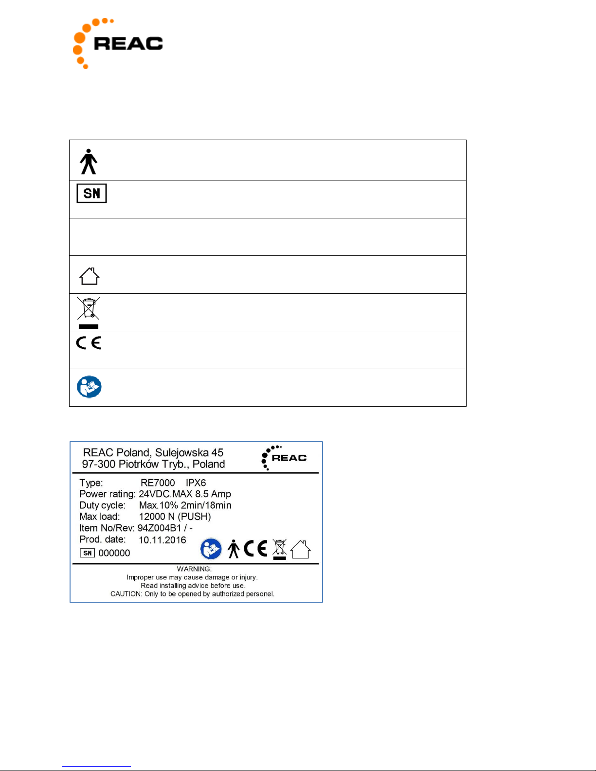
IEC 60417-5840: Patient part of type B
Serial number./LOT number
IPXX
Ingress of particles (first character) and water (second
character) as per EN60529.
IEC 60417-5957: For indoor use only
WEEE compliant
CE-label attached based on Low Voltage Directive and EMC
Directive.
ISO 7010-M002: Risk(s) mitigated in accompanying
documents
5 Labeling
The following symbols are used on the label of RE7000.
Example of label:
12

Manufacturer
Do not use if package is damaged.
Fragile, handle with care
Keep dry
Temperature limits
Relative humidity limits
Atmospheric pressure limits
Consult instructions for use (Can be ordered via REAC
homepage)
The following symbols are used on the packaging of RE7000.
13

Example of packaging information:
14

6 Complying Standards
Complying Standards
Description
Hoist Specific
ISO 10535:2006
Hoists for the transfer of disabled persons –Requirements
and test methods
Applicable parts
Electrical Safety
IEC 60601-1:2006 and
amendment 1:2012
Medical electrical equipment – Part 1: General requirements
for basic safety and essential performance.
IEC 60601-1-11:2015
Medical electrical equipment – Part 1-11: General
requirements for basic safety and essential performance –
Collateral Standard: Requirements for medical electrical
equipment and medical electrical systems used in the home
healthcare environment.
IEC 60601-1-2:2014
Medical electrical equipment – Part 1-2: General
requirements for basic safety and essential performance –
Collateral Standard: Electromagnetic disturbances –
Requirements and tests.
Electromagnetic
Emission
CISPR 11 Class B (2009)
Radiated and conducted emission
IEC 61000-3-2 (2014)
Harmonic current emission
IEC 61000-3-3 (2013)
Voltage fluctuations and flicker
Electromagnetic
Immunity
IEC 61000-4-2 (2008)
Immunity to electrostatic discharge
Test levels:
±8 kV contact discharge ±2, ±4, ±8 and ±15 kV air discharge
IEC 61000-4-3 (2006 + A1 +
A2)
Immunity to radiated electromagnetic fields in the frequency
range 80 – 1000 MHz and 1,0 – 2, 7GHz
Test levels:
80 – 1000 MHz 10 V/m with 80 % AM @ 2 Hz
1,0 – 2,7 GHz 10 V/m with 80 % AM @ 2 Hz.
IEC 60601-1-2:2014
Table 9 (up to 28 V/m pulse modulation at frequencies in ISM
bands)
IEC 61000-4-4 (2012)
Immunity to fast transients/burst
Test levels on AC Power input port: AC input/output power
input port ± 2,0 kV ncies in ISM bands)
Cont. next page
15

Electromagnetic
Immunity cont.
IEC 61000-4-5 (2006)
Surge immunity test
Test levels on AC Power input port: AC Power input port,
±0,5 kV and ±1,0 kV differential mode.
IEC 61000-4-6 (2014)
Immunity to conducted disturbances in the frequency range
0,15 – 80 MHz
Test levels on AC Power input port: 6 Vrms with 80 % AM @
2 Hz.
IEC 61000-4-8 (2009)
Immunity to power frequency magnetic fields
Test level: 30 A/m, 50 Hz and 60 Hz
IEC 61000-4-11 (2004)
Voltage Dips and Interruptions
Test levels on AC Power input port:
Test frequency: 50 Hz. Test
voltages: 100 and 230 V.
100 % for ½ cycle positive and negative half period.
60 % for 10 cycles.
30 % for 25 cycles.
100 % for 250 s.
16

© REAC, November 2016, Issue 2.0
REAC AB
REAC Poland Sp. z o.o
www.reac.se
REAC is continuously developing our products and can make changes without prior notice. Therefore we can’t guarantee that the
information stated on our webpage or in our written material always is up to date, nor can we take responsibility for any
misinterpretation of our written context. Technical specification might change due to load and external circumstances. REAC products
shall be tested in its intended application before use.
Forsbrogatan 4
662 34 Åmål, Sweden
Ul. Sulejowska 45
97-300 Piotrków Trybunalski, Poland
E-mail: info@reac.se
Phone: +46 532 78 50 00
 Loading...