


© REA Elektronik GmbH REA ScanCheck 3 - August 2010
Page 1 of 89
D-64367 Mühltal-Waschenbach
+49 (0) 6154-638 0 www.rea-verifier.de
REA
Elektronik
GmbH
Streamlining • Development • Automation
Electronic Devices and Systems
REA ScanCheck 3n
Bar Code Verification Unit
Operating Manual
Document Version 1.1.0 -20100530SC3-GUI-Version from 1.0.10.7
TD-GPT-Printer version 1.20
Verifier-Version 1.0.10.14

© REA Elektronik GmbH REA ScanCheck 3 - August 2010
Page 2 of 89
D-64367 Mühltal-Waschenbach
+49 (0) 6154-638 0 www.rea-verifier.de
REA
Elektronik
GmbH
Streamlining • Development • Automation
Electronic Devices and Systems
Table of Contents / Page 1
1.
Introduction................................................................................................................. 6
1.1
Documentation Conventions ....................................................................................... 7
1.2
Safety Instructions ...................................................................................................... 7
1.3
Determination of Serial Numbers on the REA Product ................................................ 8
2.
The Delivery Components of the REA ScanCheck 3n................................................. 9
3.
Startup of the REA ScanCheck 3n............................................................................ 11
3.1
Activation and Deactivation of the REA ScanCheck 3n............................................. 12
3.1.1
Reactivation of the REA ScanCheck 3n after Power Supply Failure ......................... 13
3.2
Changing Presets on the REA ScanCheck 3n .......................................................... 14
3.2.1
Standard Parameters of Factory Settings ................................................................. 14
3.2.2
Change Menu Language Selection........................................................................... 15
3.2.3
Change Data Output Parameters.............................................................................. 16
3.3
Operating REA ScanCheck 3n with Report Printer.................................................... 17
3.4
REA ScanCheck 3n with PC Evaluation Software..................................................... 18
3.4.1
Connection of the REA ScanCheck 3n to Power Supply ........................................... 19
3.4.2
Network Installation................................................................................................... 19
3.4.2.1
Firewall ..................................................................................................................... 20
3.4.2.2
MAC Addresses........................................................................................................ 20
3.4.2.3
Technical Functionality Test of a Network Connection.............................................. 21
3.5
Use of Extension Plates on the ScanCheck 3 ........................................................... 22
3.6
Charging the Batteries .............................................................................................. 23
3.7
Storage and Transport .............................................................................................. 24
3.8
Updating Operating Software in REA ScanCheck 3.................................................. 25
3.8.1
Updating Using a USB Memory Stick........................................................................ 25
3.8.2
Updating with the "Update Program" from the REA CD-ROM ................................... 27
3.9
Calibrating the REA ScanCheck 3n .......................................................................... 29
3.9.1
Calibrating the REA ScanCheck 3n for 6, 8 and 10 mil Apertures ............................. 30
3.9.2
Calibrating the REA ScanCheck 3n for 20 mil Aperture............................................. 31
3.9.3
Verification Tool Monitoring....................................................................................... 32
3.9.3.1
Allowable Unit Tolerances......................................................................................... 32

© REA Elektronik GmbH REA ScanCheck 3 - August 2010
Page 3 of 89
D-64367 Mühltal-Waschenbach
+49 (0) 6154-638 0 www.rea-verifier.de
REA
Elektronik
GmbH
Streamlining • Development • Automation
Electronic Devices and Systems
Table of Contents / Page 2
4.
Operation of the REA ScanCheck 3n........................................................................ 34
4.1
Handling of the REA ScanCheck 3 ........................................................................... 34
4.1.1
Instructions for Correct Execution of Code Evaluations............................................. 35
4.2
First Measurement of Bar Codes .............................................................................. 36
4.2.1
Depiction of a Code Evaluation on the REA ScanCheck 3........................................ 37
4.2.1.1
Quick Display with LED and Acoustic Signaling........................................................ 37
4.2.1.2
Evaluation of an ISO/IEC 15416 Verification - 1st Screen ......................................... 37
4.2.1.3
Evaluation of an ISO/IEC 15416 Verification - 5th Screen Optional Parameters ....... 38
4.2.1.3.1 Evaluations of an ISO/IEC 15416 - 6th Screen, Error List ......................................... 38
4.3
Adjustments / Selection of the Correct Aperture........................................................ 39
4.3.1
6, 8 and 10 mil Apertures.......................................................................................... 39
4.3.2
20 mil Aperture (Option)............................................................................................ 39
4.4
Settings / Button Functions / Setup Menu ................................................................. 42
4.4.1
General Button Assignments and Operating Functions............................................. 42
4.4.2
Buttons with Special Functions ................................................................................. 44
4.5
Setup Menu Structure ............................................................................................... 46
4.6
Setup Main Menu "Configuration" with 6 Sub-Menus................................................ 46
4.6.1
Setup Sub-Menu 1 - Measurement Archive............................................................... 46
4.6.2
Setup Sub-Menu 2 Calibration .................................................................................. 47
4.6.3
Setup Sub-Menu 3 Settings with 9 Additional Sub-Menus......................................... 47
4.6.3.1
Setup Sub-Menu 3 Settings - Sub-Menu 1 Code Type Selection - Code Type Tables47
4.6.3.1.1 Code Selection ......................................................................................................... 49
4.6.3.2
Setup Sub-Menu 3 Settings - 1 Code Type Selection - Additional Verification Criteria50
4.6.3.2.1 The EAN / UPC Code Family.................................................................................... 50
4.6.3.2.2 EAN-13 - Additional Verification Criteria.................................................................... 50
4.6.3.2.3 UPC-A Code - Additional Verification Criteria............................................................ 52
4.6.3.2.4 EAN-8 Code - Additional Verification Criteria ............................................................ 53
4.6.3.2.5 UPC-E Code - Additional Verification Criteria............................................................ 53
4.6.3.3
The Code 128 Family................................................................................................ 54
4.6.3.3.1 GS1-128 - Additional Verification Criteria.................................................................. 54
4.6.3.3.2 The GS1 DataBar Code Family................................................................................. 56
4.6.3.3.3 RSS / GS1 DataBar Code - Additional Verification Criteria ....................................... 56
4.6.3.3.4 The Code 39 Family.................................................................................................. 56
4.6.3.3.5 Code 39 - Additional Verification Criteria................................................................... 56
4.6.3.3.6 Code 39 – Full ASCII - Additional Verification Criteria............................................... 57
4.6.3.3.7 PZN Codes - Additional Verification Criteria.............................................................. 58
4.6.3.3.8 Codabar - Additional Verification Criteria (Optional).................................................. 58
4.6.3.3.9 ITF-14 Code - Additional Verification Criteria ............................................................ 59
4.6.3.3.10 2/5i Code - Additional Verification Criteria................................................................. 59

© REA Elektronik GmbH REA ScanCheck 3 - August 2010
Page 4 of 89
D-64367 Mühltal-Waschenbach
+49 (0) 6154-638 0 www.rea-verifier.de
REA
Elektronik
GmbH
Streamlining • Development • Automation
Electronic Devices and Systems
Table of Contents / Page 3
4.6.3.3.11 Plessey Code - Additional Verification Criteria (
Not Yet Available in the Current Version
)60
4.6.3.3.12 MSI Code - Additional Verification Criteria ................................................................ 60
4.6.3.3.13 Pharma and Mini Pharma Code - Additional Verification Criteria............................... 61
4.6.3.3.14 Setup Menu 3 Settings - 2 Aperture.......................................................................... 61
4.6.3.3.15 Setup Menu 3 Settings - 3 Evaluation ....................................................................... 61
4.6.3.3.16 Setup Menu 3 Settings - 3 Evaluation - First Sub-Menu Page................................... 62
4.6.3.3.17 Setup Menu 3 Settings - 3 Evaluation - Second Sub-Menu Page.............................. 62
4.6.3.3.18 Setup Menu 3 Settings - 3 Evaluation - Third Sub-Menu Page.................................. 63
4.6.3.3.19 Setup Menu 3 Settings - 3 Evaluation - Fourth Sub-Menu Page ............................... 64
4.6.3.4
Setup Menu 3 Settings - 4 Unit Configuration with 8 Sub-Menus .............................. 65
4.6.3.4.1 Setup Menu 3 Settings - 4 Unit Configuration - 1 Operating Modes .......................... 65
4.6.3.4.2 Setup Menu 3 Settings - 4 Unit Configuration - 2 Output Parameters........................ 67
4.6.3.4.3 Setup Menu 3 Settings - 4 Unit Configuration - 3 Options......................................... 69
4.6.3.4.4 Setup Menu 3 Settings - 4 Unit Configuration - 4 Date and Time .............................. 69
4.6.3.4.5 Setup Menu 3 Settings - 4 Unit Configuration - 5 Network Parameters ..................... 70
4.6.3.4.6 Setup Menu 3 Settings - 4 Unit Configuration - 6 Password...................................... 70
4.6.3.4.7 Setup Menu 3 Settings - 4 Unit Configuration - 7 Company/User Information ........... 71
4.6.3.4.8 Setup Menu 3 Settings - 4 Unit Configuration - 8 Printing Parameters ...................... 71
4.6.3.5
Setup Menu 3 Settings - 5 Code Comparator (Option Only)...................................... 72
4.6.3.6
Setup Menu 3 Settings - 6 Article Search (Option Only)............................................ 73
4.6.4
Setup Menu 5 Article Trigger (Option for Article Database)....................................... 73
4.6.4.1
Setup Menu 3 Settings - 7 RESET to Factory Settings ............................................. 73
4.6.4.2
Setup Menu 3 Settings - 8 USB Update.................................................................... 74
4.6.4.3
Setup Menu 3 Settings - 9 Language........................................................................ 74
4.6.5
Setup Menu 4 Document Editing (from Version 1.0.8.12).......................................... 74
4.6.5.1
Setup Menu 4 Document Editing "Order Number"..................................................... 75
4.6.5.2
Setup Menu 4 Document Editing "User Comment" ................................................... 75
4.6.5.3
Setup Menu 5 System Information............................................................................ 76
5.
Appendix Standards and Literature on Bar Code Verification Units........................... 77
6.
Appendix Glossary of Technical Code Verification Terms ........................................ 79
7.
Appendix Technical Data - REA ScanCheck 3n........................................................ 82
7.1
Appendix Technical Data - PoE Power Supply / Charger for REA ScanCheck 3n.... 84

© REA Elektronik GmbH REA ScanCheck 3 - August 2010
Page 5 of 89
D-64367 Mühltal-Waschenbach
+49 (0) 6154-638 0 www.rea-verifier.de
REA
Elektronik
GmbH
Streamlining • Development • Automation
Electronic Devices and Systems
Table of Contents / Page 4
8.
Intellectual Property Provision................................................................................... 85
9.
Environmental Protection.......................................................................................... 85
10.
Appendix - Warranty Terms ...................................................................................... 86
11.
Appendix - CE Conformity Statement for REA ScanCheck 3 .................................... 87
12.
Appendix ISO/IEC Conformity Certificate for REA ScanCheck 3............................... 88
13.
Appendix - Conformity Confirmation for Verifier Calibration Card.............................. 89

© REA Elektronik GmbH REA ScanCheck 3 - August 2010
Page 6 of 89
D-64367 Mühltal-Waschenbach
+49 (0) 6154-638 0 www.rea-verifier.de
REA
Elektronik
GmbH
Streamlining • Development • Automation
Electronic Devices and Systems
1. Introduction
The REA ScanCheck 3n is a mobile bar code verification unit for zero-contact inspection of the quality
of printed linear and stacked bar codes. It can be used in a portable manner on site for quick
evaluation. The verification result "good" or "error" is represented both by acoustic signals and visually
by means of multi-colored LED displays. The detailed measurement results can be stored in the
internal memory and shown on the color display. The evaluations can also be printed out with an
optionally available record printer. With the optional expansion, the ScanCheck3 can also be
connected to a PC with the REA TransWin32 software for remote control and evaluation via network
cable.
The important details of the evaluations can be read on the color display.
The arrow buttons can be used to page forward and back to additional menu fields or screen pages.
The additional detailed information can be provided via the printing of records. The unit is consequently
well suited for use in printing process control and quality control of codes on products in goods
receiving.
For evaluating film masters, applicability is limited to the reading and decoding of codes and
comparison of their content with a template.
All bar code evaluation units from REA Elektronik GmbH offer code evaluation according to the
ISO/IEC 15416 standard. The measurement and evaluation of additional, optional parameters is
additionally available. With these evaluation parameters (previously called traditional measurement
values), more detailed requirements can be evaluated, particularly for optimization of the printing
process.
Evaluations according to ISO/IEC 15416 are also known as CEN or ANSI evaluations and are also
described as ISO evaluations. In North America, the standard methods ANSI X3 182-1990 and
ANSI/UCC5 apply. The European standard EN 1635 has meanwhile been retracted (CEN evaluation).
The measurements, formerly called "traditional evaluation," are replaced by the optional parameters.
Optional parameters are based on the respective symbology standards. For EAN/UPC codes, for
example, this is the standard ISO/IEC 15420. The evaluation of optional parameters can be
categorized in classes, as in ISO/IEC 15416. This enables one to obtain a clear evaluation result,
based on previously specified, individual quality requirements.

© REA Elektronik GmbH REA ScanCheck 3 - August 2010
Page 7 of 89
D-64367 Mühltal-Waschenbach
+49 (0) 6154-638 0 www.rea-verifier.de
REA
Elektronik
GmbH
Streamlining • Development • Automation
Electronic Devices and Systems
1.1 Documentation Conventions
In order to be able to clearly represent complicated subject matter, a special depiction was selected for
each of specific processes.
• If a specific button is to be pressed or a selection made from a list, this is described in angle
brackets: <Tab>
• Buttons to be pressed in sequence are placed adjacent to one another in the textual depiction:
<Menu> <8> <OK>
• Program names and window titles are printed in bold
• Text inputs are shown in square brackets: [File Name]
• Upon calling up programs, the program names (bold) are not set in square brackets. Any text inputs
(parameter/path/file name...) related to the program call, however, are in square brackets for
identification: BCT_SEND [File Name]
• The calling of executable files (file extension: EXE and BAT) is normally completed with the <OK
Enter> button. In order to increase comprehensibility of the depiction, "…process is
started/confirmed with <Enter>" is omitted on the depiction and explanation in most cases
• Cross-references to other chapters are set in " " and printed in italics: (See Chpt. "xxx" page xx)
Warning notices indicate operations that must be observed in order to protect the operator, the
unit and the data from damage. They are specially highlighted in a frame.
Good to know
Information that is important for better understanding and correct handling are supplied with
this symbol and shown in a frame.
1.2 Safety Instructions
This REA product was correspondingly developed, manufactured and inspected before delivery in
consideration of the current safety requirements of the corresponding standards for electrical safety. As
with any electrical device, it is important to know the possible risks and to operate it correctly. The
safety instructions were created in order to effectively protect the operator and other people nearby
from possible damage.
Before starting and operating the REA product, be sure to read and observe the operating instructions
and especially the safety instructions very carefully.
© REA Elektronik GmbH REA ScanCheck 3 - August 2010
Page 8 of 89
D-64367 Mühltal-Waschenbach
+49 (0) 6154-638 0 www.rea-verifier.de
REA
Elektronik
GmbH
Streamlining • Development • Automation
Electronic Devices and Systems
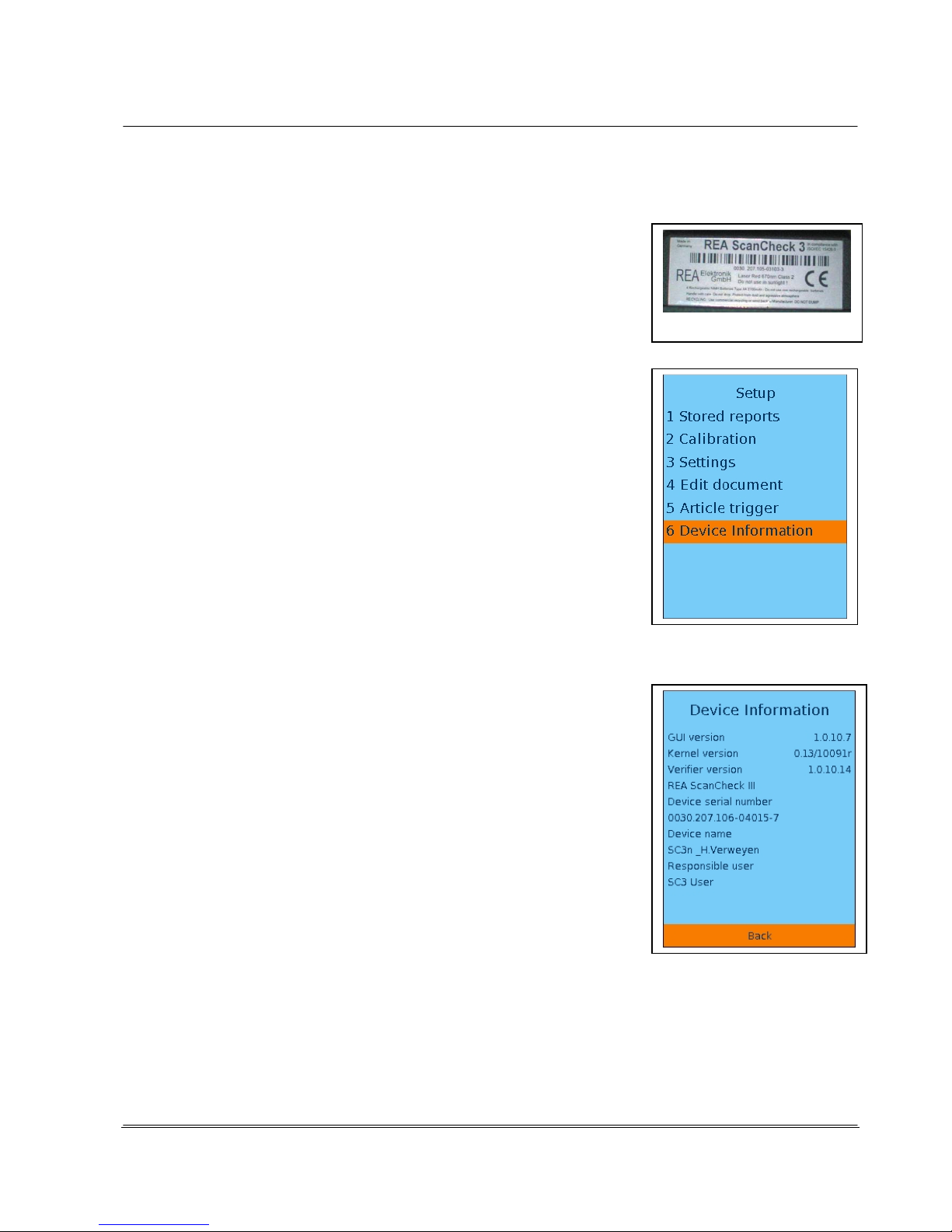
1.3 Determination of Serial Numbers on the REA Product
For contact with the manufacturer or a system partner, it is important to
indicate the precise type and the serial number of the affected REA
product. This information can be found on the company label on the
hardware together with the article number.
Please notate this information on your delivery documents and always
use it when corresponding with REA Elektronik or an authorized system
or service partner.
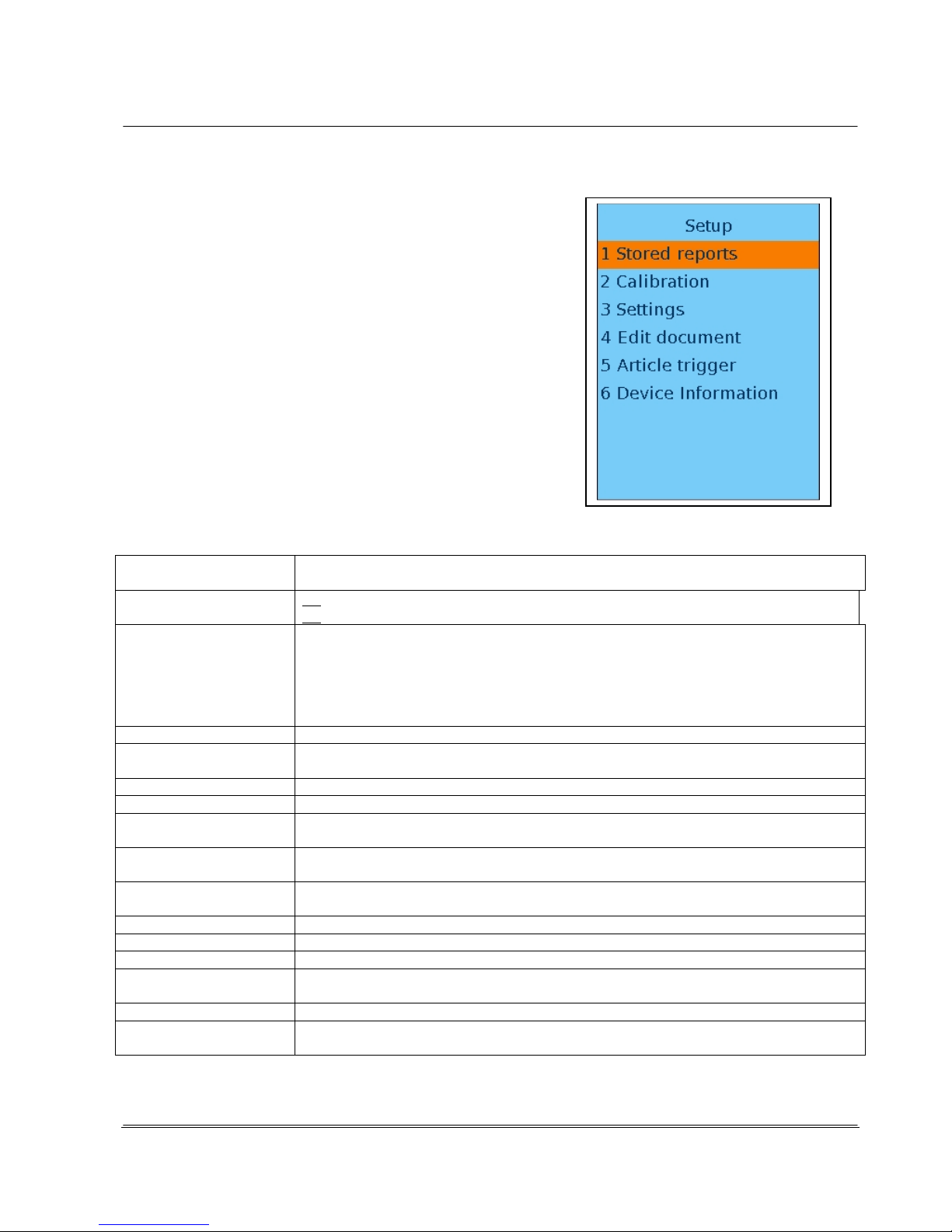
If the unit is already in operation, the system information can be called
up from the Setup menu via the menu item "5 System Info."
Button sequence: <Setup> <5 Systeminfo>
Version of operating program (GUI software)
Version of core operating software
Version of verifier evaluation software
Serial number of the unit. 0030.207.106-0XXXX-X
This should be identical to the serial number on the ID plate.
The unit name: Standard: SC3_Master
User name: Standard: SC3 User

© REA Elektronik GmbH REA ScanCheck 3 - August 2010
Page 9 of 89
D-64367 Mühltal-Waschenbach
+49 (0) 6154-638 0 www.rea-verifier.de
REA
Elektronik
GmbH
Streamlining • Development • Automation
Electronic Devices and Systems
2. The Delivery Components of the REA ScanCheck 3n
In the standard version, the REA ScanCheck 3n is supplied in the following configuration and always in
a specialized transport box with form insert.
A REA ScanCheck 3n consists of the following components
(Network PoE version from May 2009):
• Bar code verification unit REA ScanCheck 3n
• Calibration card for white balance and code size calibration incl. protocol of a reference
measurement for verification tool monitoring
• Operating manual (this document)
• Transport box with special fitted foam, optional transport case
• Four rechargeable Mignon NiMH AA batteries (already installed in the REA ScanCheck 3's
battery compartment)
• 1 PoE power supply (100 - 240 volts~; 0.4A; 50-60Hz~) with cold unit socket according to
IEC-60320 C5 / C6
• Power connection cable with cold unit plug and power plug for the standard ordered (Euro, UK,
USA)
• 2 network cables, highly flexible, RJ45 CAT5, approx. 2 m long
• 1 cross-over adapter for using a network cable with rotated connections
• 1 CD-ROM with all REA Verifier documents and program files
A REA ScanCheck 3 consists of the following components (USB version up to May 2009):
• Bar code verification unit REA ScanCheck 3
• Calibration card for white balance and code size calibration incl. protocol of a reference
measurement for verification tool monitoring
• Operating manual (this document)
• Transport box with special fitted foam, alternatively transport case
• Four rechargeable Mignon NiMH AA batteries (already installed in the REA ScanCheck 3's
battery compartment)
• Universal plug power supply (100 - 240V), secondary 9V, with connection cable with low
voltage hollow plug socket
• Primary plug adapter (EURO, UK or US according to delivery country, already installed)
• Connection cable for data interface and charge unit (cable with CompShield plug, hollow plug
and USB plug, type A)

© REA Elektronik GmbH REA ScanCheck 3 - August 2010
Page 10 of 89
D-64367 Mühltal-Waschenbach
+49 (0) 6154-638 0 www.rea-verifier.de
REA
Elektronik
GmbH
Streamlining • Development • Automation
Electronic Devices and Systems
Options / Alternatives (only present if ordered, see delivery note)
Hardware:
• Extension plate made of Plexiglas with 82.5 mm cut-out
• Extension plate made of Plexiglas with 175 mm cut-out
• 20 mil adapter for using the 20 mil aperture function
• Portable protocol printer, type TD-GPT-U with 2 rolls of thermal paper
• Connection cable for protocol printer
• Power supply for protocol printer
• Unit case in place of cardboard packaging, black, plastic
Software:
• REA TransWin32 PC program with operating manual for capturing, evaluation and saving
measurement protocols on a PC with MS-WINDOWS operating system;
this program is most often used as an alternative to the protocol printer (internal software option
usable via activation code)
• Article database software with operating manual (internal software option usable via activation
code)
• Code comparator function (internal software option usable via activation code)
• Optional code types (internal software option usable via activation code)
All software options can be freely activated and operated exclusively with the serial number of a REA
ScanCheck 3n. A REA ScanCheck 3n will not work with TransWin32 software or another software
option without the corresponding activation code if the activation key is not correct.
The license key is inseparably linked to the respective REA ScanCheck 3n.
Software options that are provided with a new unit are made available before delivery and require no
additional license key for activation.

© REA Elektronik GmbH REA ScanCheck 3 - August 2010
Page 11 of 89
D-64367 Mühltal-Waschenbach
+49 (0) 6154-638 0 www.rea-verifier.de
REA
Elektronik
GmbH
Streamlining • Development • Automation
Electronic Devices and Systems
3. Startup of the REA ScanCheck 3n
Special installation on the REA ScanCheck 3n is no longer required. It is delivered ready to operate.
The unit is configured for a standard presetting and can inspect and evaluate most code types
according to the GS1 standard requirements immediately after activation.
The four NiMH batteries provided have an especially low discharge rate.
They are already installed in the battery compartment before delivery.
It is also possible to use 4 Mignon primary batteries instead of the 4 batteries.
In the case of heavily discharged batteries and no power supply
connection, the REA ScanCheck 3n can be activated briefly after
startup. The activation process is interrupted and the unit shows no
further response. In this case, the batteries are probably empty or
even incorrectly installed.
There is continuous monitoring of battery voltage during operation
with rechargeable (or non-rechargeable) batteries.
When the voltage reaches a critical threshold, an electronically
monitored charging process is started or completed.
If the operating voltage value sinks below a critical threshold, the unit
outputs a corresponding warning message and ends the operating
program, saving the settings.
Attention:
If the REA ScanCheck 3n is operated by non-rechargeable batteries instead of rechargeable
batteries, the power supply must never be connected. Connection of the power supply will lead
to destruction of the batteries and, with a high degree of probability, to the destruction of the
unit as well.
Any manufacturer's warranty is thereby voided.
When the PoE power charger is correctly connected, the recharging of the rechargeable batteries
takes place automatically and is monitored electronically (see also Chapter 3.4.1). Over-charging or
over-heating is monitored and prevented by corresponding protection circuits.
If the unit is operated during the charging process, the complete charging of the rechargeable batteries
will take correspondingly longer than it would with the unit deactivated.
The unit also operates properly if no rechargeable batteries are installed, only one cell is missing but
the power supply is correctly connected and connected to the mains voltage.
Upon removal of the connection cable, however, all programs will immediately end without saving data
or settings and without pre-warning.
If the rechargeable batteries are heavily discharged, there is risk that the rechargeable batteries will not
be recognized by the charging circuit (charging LED remains off). In this case, the rechargeable
batteries must be replaced. In some cases, the rechargeable batteries can be reactivated by an
external charger with single-cell charging.

© REA Elektronik GmbH REA ScanCheck 3 - August 2010
Page 12 of 89
D-64367 Mühltal-Waschenbach
+49 (0) 6154-638 0 www.rea-verifier.de
REA
Elektronik
GmbH
Streamlining • Development • Automation
Electronic Devices and Systems
3.1 Activation and Deactivation of the REA ScanCheck 3n
The device is activated by pressing the red <ON> button.
Upon initial activation, the green "On LED" lights up. It takes 30-50
seconds until all programs are initialized. Only then does the main screen
appear as shown at right.
Once the REA ScanCheck 3 has been activated, it can be deactivated by
pressing the <ON> button again.The display then opens the menu window
for various modes.
The colored focus can be moved to the desired command with the arrow
keys and then confirmed with the <OK Enter> button.
The digit in front of the menu item can also be activated by pressing the
corresponding number button <1...6> and thereby immediately initiating the
desired function.
1. Sleep Mode
Sets the unit to a power-saving sleep mode in which the display
and other drivers are deactivated and the processor continues to
operate at the lowest power consumption.
It can be immediately reactivated from this mode by pressing the
<ON> button. The sleep mode should be activated automatically
via the unit settings after a pre-specified time in order to save
power in rechargeable battery mode.
2. Shut down device
Completely deactivates the unit and closes all programs. You
should select this function when the unit will not be used for an
extended period, such as at the end of measurements or work day.
A minor amount of energy is also required from the rechargeable
batteries or power supply in this operating mode.
3. Reboot device
A restart of the complete system can be carried out with this menu
item. Executing this command can be helpful if the unit no longer
responds as expected.
4. Terminate GUI (Graphical User Interface)
This can be used to close the program for the graphical user
interface. Execution of this command is only useful for service
purposes.
The REA ScanCheck 3n display becomes black/white.
The operating system only displays the text line editor. This then
responds only to corresponding text commands.
The cursor blinks at the first position of the entry field after
indication of the operating system version number
(0.9 in this case)
#_
Entering the following command sequence can restart the GUI:
<1>, <OK Enter>.
The restart takes several seconds.

© REA Elektronik GmbH REA ScanCheck 3 - August 2010
Page 13 of 89
D-64367 Mühltal-Waschenbach
+49 (0) 6154-638 0 www.rea-verifier.de
REA
Elektronik
GmbH
Streamlining • Development • Automation
Electronic Devices and Systems
The REA ScanCheck 3n can also be completely deactivated from this menu with the key
sequence <ON>, <OK Enter>.
If a software update is carried out with a USB memory stick in this operating mode, this can be
started with the command sequence <6>, <OK Enter>.
5. Reboot Verifier
With this menu item, the verifier program for the code evaluation can also be restarted. A
restart can be useful if, for example, data communication with the PC program no longer
responds normally.
3.1.1 Reactivation of the REA ScanCheck 3n after Power Supply Failure
If the unit is suddenly disconnected from power, such as by removal of one of the batteries, by deep
discharging or by separation of the mains supply in an operating mode without installed
batteries/rechargeable batteries and without proper closing of programs, the unit cannot be restarted
immediately upon first pressing the red <ON> button.
Upon initial activation after a crash of this kind, all improperly closed programs must first be reinitialized
and properly closed. The screen then remains dark, the green "On LED" goes out and the unit remains
deactivated.
The unit is not properly started until pressing the red <ON> button again.
The green "ON LED" lights up and after the activation delay, the unit operates properly again.
© REA Elektronik GmbH REA ScanCheck 3 - August 2010
Page 14 of 89
D-64367 Mühltal-Waschenbach
+49 (0) 6154-638 0 www.rea-verifier.de
REA
Elektronik
GmbH
Streamlining • Development • Automation
Electronic Devices and Systems
3.2 Changing Presets on the REA ScanCheck 3n
The REA ScanCheck 3 is configured to a standard
configuration, the "factory settings," ex factory or after a
RESET, with which most user bar code verifications can be
carried out immediately and without additional settings.
In order to be able to make basic and other individual presets
for operation on the unit, <3 Settings> can be selected in the
menu that appears after pressing <Setup> and confirmed with
<OK>.
Any sub-menu window can be closed without accepting
changes to the settings by pressing the <ESC> button. The
top-level menu window is then displayed again.
3.2.1 Standard Parameters of Factory Settings
Operating Mode
Unit switches to power saving mode after 10 min.
Unit shuts down completely after 60 min.
Output Parameters:
No automatic print output after a measurement
No automatic saving of measurements
Code Type Selection:
According to standard code list. Searching all possible code types; the respective
structure verification is not active.
In the case of GS1 codes, EAN structures and module sizes are verified and
evaluated.
The size verification takes place for the respective general tolerance range.
The verification of AI file contents is deactivated.
Aperture:
6 mil
Evaluation:
According to ISO/IEC standard 15416 incl. verification and evaluation according to
respective code standard for all optional parameters
Optional Parameters:
All parameters are switched active for display and for evaluation
Selected Class:
Only parameters with grade / class 3 and better result in total result "Good"
Number of
Measurements:
3 measurements are preset when selecting multiple measurement. Non-decoded
individual measurements are not considered in the total evaluation
Metric Deviations:
Indicators for bars - gaps - E-value - P-value are indicated as relative values in [%]
rounded up or down to "5"
Optional Software
Expansions:
Activated as previously, e.g.: Code comparator, article database function, etc.
Language:
English
Day and Time:
Unchanged
Network Settings:
Unchanged
Company/User
Information:
Unit name, user name, company information are overwritten with the REA factory
specifications
Password:
Overwritten with spaces
Format of Report PrintOut:
Long version complete, prints all elements that can be selected

© REA Elektronik GmbH REA ScanCheck 3 - August 2010
Page 15 of 89
D-64367 Mühltal-Waschenbach
+49 (0) 6154-638 0 www.rea-verifier.de
REA
Elektronik
GmbH
Streamlining • Development • Automation
Electronic Devices and Systems
3.2.2 Change Menu Language Selection
The unit is preset to the national language of the delivery country
before shipment. It can happen that the operator desires a
different menu language than the one that is preset.
The language selection can be changed via the keyboard
commands <Setup>, <3 Settings> <9 Language>.
The desired language can be selected from the list in the submenu by moving the orange-colored focus to the desired
language field with the arrow buttons and then confirming by
pressing the <OK Enter> button. The field in front of the
language changes correspondingly and is activated.
With the <Store> button or the cursor on <OK> and confirming
with <OK Enter>, the new language setting is accepted.
From that point on, all menu dialogues and the texts of the
reports will be output in the newly selected language (English, in
this case).
The provision of additional languages is also scheduled for
future software versions.

© REA Elektronik GmbH REA ScanCheck 3 - August 2010
Page 16 of 89
D-64367 Mühltal-Waschenbach
+49 (0) 6154-638 0 www.rea-verifier.de
REA
Elektronik
GmbH
Streamlining • Development • Automation
Electronic Devices and Systems
3.2.3 Change Data Output Parameters
Back to the sub-menu for the settings.
The sub-menu for the possible settings follows.
With <4 Unit Configuration>, another sub-menu appears in which the
basic settings can be made.
Under the sub-menu "1 Operating Mode Settings," it can be set:
• whether and at what interval the unit switches to sleep mode or
deactivates completely after the last operation
• whether the installed signal tone encoder is activated or deactivated.
Under the sub-menu "2 Output Parameters," it can be selected in another
sub-menu:
• whether the measurement reports are to be automatically or manually
printed on the connected report printer
• whether the output of the measurement reports should take place via
the connected report printer.
If the TD-GPT-USB printer is to be used to create measurement
reports on site, this menu item must be activated.
The corresponding measurement reports are then always printed when
the button <Print L> or <Print S> is pressed on the REA ScanCheck
3n.
• If the unit is connected via the connection cable to the PC on which the
evaluation software REA TransWin32 is installed and operated and if
the activation code for operating with this software has been entered on
the unit and activated, the evaluations of the measurements can
additionally be executed via the PC program REA TransWin32.
• Whether the measurement reports should always automatically be
saved in the memory of the REA ScanCheck 3n
• or saving should only take place upon command
• or only when explicitly commanded with the <Store> button

© REA Elektronik GmbH REA ScanCheck 3 - August 2010
Page 17 of 89
D-64367 Mühltal-Waschenbach
+49 (0) 6154-638 0 www.rea-verifier.de
REA
Elektronik
GmbH
Streamlining • Development • Automation
Electronic Devices and Systems
3.3 Operating REA ScanCheck 3n with Report Printer
The REA ScanCheck 3n verification unit can also be operated together with the portable report printer
type REA TD-GPT-U.
The printer is first connected with the supplied connection cable via the Mini USB plug and then with
the Type A USB plug to the USB socket to the lower face of the REA ScanCheck 3.
The printer has its own power supply via an installed battery.
This must be completely charged before use with the supplied printer power supply.
(see also operating manual for the portable printer REA TD-GPT-U).
A compact plug charger for charging the internal battery with 6 volts of output voltage is supplied with
the printer. Interchanging the plug power supply for the REA ScanCheck 3n is not possible. The
specifications in the REA TD-GPT-U operating manual must be observed for all other operating
instructions for the report printer.
Operation with other printers is not possible and not intended.
The predecessor model REA ScanCheck 3, which could be connected to a PC via USB, was supplied with a 9V
power supply. The printer power supply and the ScanCheck 3 power supply could be interchanged in this
configuration.

© REA Elektronik GmbH REA ScanCheck 3 - August 2010
Page 18 of 89
D-64367 Mühltal-Waschenbach
+49 (0) 6154-638 0 www.rea-verifier.de
REA
Elektronik
GmbH
Streamlining • Development • Automation
Electronic Devices and Systems
3.4 REA ScanCheck 3n with PC Evaluation Software
The REA ScanCheck 3n can be operated independently, connected to the portable REA TD-GPT-U
printer as well as on a PC with optional PC software programs REA TransWin32 or REA Article
Database 32.
The unit has 2 different plug sockets on the lower face for
the corresponding connections. The REA ScanCheck 3n
can be connected with the report printer with the right
USB host port, type A, via the supplied USB connection
cable and verification reports can thereby be printed out.
Via the left-hand RJ45 type network port, the
REA ScanCheck 3n can be connected to the supplied
PoE power supply via the supplied network cable and
operated. The network cable provides the external power
supply as well as data communication via TCP-IP protocol. The connection options are described
below.
The software REA TransWin32 is not included in the standard scope of delivery of a REA ScanCheck 3n. If
REA TransWin 32 was ordered, the necessary license key is already stored in the verification unit ex
factory. If not equipped until later, a license key supplied with the delivery note must be entered on the unit
(see Chapter 4.6.3.4.3).
The PC used for the program REA TransWin32 should have the following hardware configuration at
minimum:
- CPU processor with 1.5 GHz and at least 1 GB RAM
- Hard drive with at least 500 MB of free storage space
- Color graphics card with minimum resolution of the monitor
- 1 CD-ROM or DVD drive
- 1 free USB 1.1 interface (for connecting REA ScanCheck 3, REA PC-Scan)
- 1 serial interface (for connecting REA PC-Scan, REA ScanCheck and REA ScanCheck II as well as
REA Check 3)
- 1 color monitor with at least 1280 x 1024 pixel resolution or more
The software configuration should be at least the following:
- Microsoft Windows 2000 with SP4, Windows XP with SP2 or Windows Vista
- .NET Framework from vers. 2.0
- Microsoft Internet Explorer IE from version 6.0
- Microsoft Windows Installer from version 3.1
The software was successfully tested with operating software versions Microsoft Windows 2000 with
Service Pack 4, Windows XP Professional with Service Pack 2, Windows 7 and Windows Installer 3.1.
Additional details on unit connection to the PC network can be found both in the manual for
REA TransWin32 and in the separate document on network installation of REA Verifiers on the REA Verifier
CD-ROM.
Administrator rights are required for installation of the software and configuration on the PC. If the user
account does not have administrator rights, the installation aborts with a corresponding error message.

© REA Elektronik GmbH REA ScanCheck 3 - August 2010
Page 19 of 89
D-64367 Mühltal-Waschenbach
+49 (0) 6154-638 0 www.rea-verifier.de
REA
Elektronik
GmbH
Streamlining • Development • Automation
Electronic Devices and Systems
3.4.1 Connection of the REA ScanCheck 3n to Power Supply
The REA ScanCheck 3n can only be operated for a limited
time via the supplied and installed rechargeable batteries
independent of the power supply.
No later than when the unit outputs the warning message
"Batteries empty," the REA ScanCheck 3n must be connected
to the power network via the PoE power supply included in the
scope of supply and with the supplied network cable. The plug
types are specified in the standard IEC 60320. The socket on
the power supply has type C6 and the plug on the connection
cable has type C5.
The "Data In" socket must be connected to the existing network
installation.
The "Data Out" socket must be connected to the REA
ScanCheck 3n with the help of one of the supplied network
cables. The "Data Out" socket supplies the power supply for the
REA ScanCheck 3n and, simultaneously, the interface for the
network data communication.
3.4.2 Network Installation
No driver installation is required for the REA ScanCheck 3n. No network configuration must be made,
either, as this normally takes place automatically (basic setting ex factory).
The REA ScanCheck 3n is connected to the PC via the network. The cabling can be implemented as
follows:
• The PC and the REA ScanCheck 3n are each connected to one network connection socket in
the room (DHCP mode)
• The PC and the REA ScanCheck 3n are connected directly (ZeroConfig or fixed IP address)
• The PC and the REA ScanCheck 3n are connected via an Ethernet switch (ZeroConfig or fixed
IP address)

© REA Elektronik GmbH REA ScanCheck 3 - August 2010
Page 20 of 89
D-64367 Mühltal-Waschenbach
+49 (0) 6154-638 0 www.rea-verifier.de
REA
Elektronik
GmbH
Streamlining • Development • Automation
Electronic Devices and Systems
• The PC and the REA ScanCheck 3n are connected via an Ethernet switch and the Ethernet
switch is connected to the network (DHCP mode).
DHCP Mode: The PC and the REA ScanCheck 3n are in the company network and obtain the network
configuration via the DHCP server. This mode is active in the factory settings.
ZeroConfig Mode: The PC and the REA ScanCheck 3n are connected directly.
Because no server can be reached (due to the direct point-to-point connection), the
setting falls back to the no-configuration network setting (called ZeroConfig). This
mode is active in the factory settings. The PC network adapter reports the status
"Limited or no connectivity."
ZeroConfig mode is reached after a wait time of about 1 - 2 minutes. During the waiting period, the PC
displays a network icon with a moving yellow dot in the status bar. No connection is possible in this
status.
When the automatic configuration is complete, the network icon is displayed with the
yellow exclamation mark. Communication is now possible and active.
Fixed IP Address Mode: Fixed addresses are issued by IT administration. This mode must be
manually adjusted.
The settings on the REA ScanCheck 3n must be set to DHCP "ON" and ZeroConfig "ON" (factory
settings). The setting only has to be changed if manually fixed IP addresses are to be issued.
3.4.2.1 Firewall
A so-called firewall is always activated on correctly configured PCs. The firewall may not block the
network communication between the PC and the REA ScanCheck 3n.
3.4.2.2 MAC Addresses
Every network-capable device receives a hardware address or a hardware serial number,
which is unique worldwide. This number is called a MAC address. If only known devices are integrated
into the user network for security reasons, this MAC address must be entered in the system (see
Display Network Configuration in Chapter 3.4.2).

© REA Elektronik GmbH REA ScanCheck 3 - August 2010
Page 21 of 89
D-64367 Mühltal-Waschenbach
+49 (0) 6154-638 0 www.rea-verifier.de
REA
Elektronik
GmbH
Streamlining • Development • Automation
Electronic Devices and Systems
3.4.2.3 Technical Functionality Test of a Network Connection
The TCP/IP connection can be inspected with
Windows help programs.
Select the following with the left mouse button:
<Start>, <All Programs>, <Accessories> and
then click on <Command Prompt> with the left
mouse button.
A new window with the command prompt
opens.
Computer commands oriented by text lines (as
in a DOS program) can be entered here.
Enter the command <ping 192.168.222.22> in the command prompt and confirm with ENTER. The IP
address must be the respective IP address of the connected REA ScanCheck 3n.
Attention: other IP addresses are used in this image as examples.
After a few seconds, new text lines appear with specifications on the response times of the pinged IP
address or error messages.
With this test, it can be determined whether the TCP/IP connection between the IP address of the REA
verification unit and the IP address of the PC network interface is generally functioning.
If there is no reply shown like in the image above or there is an error / timeout message, the installation
must be checked and corrected.

© REA Elektronik GmbH REA ScanCheck 3 - August 2010
Page 22 of 89
D-64367 Mühltal-Waschenbach
+49 (0) 6154-638 0 www.rea-verifier.de
REA
Elektronik
GmbH
Streamlining • Development • Automation
Electronic Devices and Systems
3.5 Use of Extension Plates on the ScanCheck 3
Transparent extension plates with various cut-out widths can be used as accessories for the REA
ScanCheck 3n. To do so, the standard-installed trapezoidal transparent base plate is removed and
replaced by one of the extension plates.
Extension plate with 82.5 mm cut-out Extension plate with 175 mm cut-out
The use of extension plates is always recommended when labels or films must be pressed flat on the
underlay because otherwise the label material can wrinkle up.
They are indispensable if codes must be measured on round surfaces (e.g. barrels, cans, etc.). They
are also required if bar codes must be measured at positions or on articles with too small of a surface
for positioning the unit.
Attention:
Extension plates must always be removed for calibration.

© REA Elektronik GmbH REA ScanCheck 3 - August 2010
Page 23 of 89
D-64367 Mühltal-Waschenbach
+49 (0) 6154-638 0 www.rea-verifier.de
REA
Elektronik
GmbH
Streamlining • Development • Automation
Electronic Devices and Systems
3.6 Charging the Batteries
4 NiMH Mignon batteries (size AA) are included in the battery compartment of the unit upon delivery.
These have been inspected, charged and installed in the battery compartment before delivery. With
new and completely charged batteries, the REA ScanCheck 3n can be operated without interruption for
about 2 to 3 hours. If the energy-saving function is used for automatic deactivation of the unit, the
operating time can be significantly extended.
To charge the batteries, they do not normally have to be removed. The PoE power supply is simply
connected with the network cable and connected to a socket with its mains plug. The green LED on the
power supply lights up for verification.
In addition, a supplied network connection cable is connected to the "OUT" socket on the power supply
and the RJ45 socket on the REA ScanCheck 3n (see also Chapter 3 and 3.4).
The charge time equals at least approximately 4 hours with empty batteries. During charging, the righthand green LED underneath the display with the label "charge" lights up on the REA ScanCheck 3n.
It goes out once the charge is complete and no further charging is carried out or if the power supply is
emitting no voltage. In cases of emergency, operation with Mignon batteries (non-rechargeable primary
cells) is permitted.
Attention:
REA Elektronik does not recommend using non-rechargeable primary cells (Mignon batteries)
in the REA ScanCheck 3n. These may never be charged. If the charger is connected by
accident, there is risk of damaging or destroying the batteries and the unit with the charge
current.

© REA Elektronik GmbH REA ScanCheck 3 - August 2010
Page 24 of 89
D-64367 Mühltal-Waschenbach
+49 (0) 6154-638 0 www.rea-verifier.de
REA
Elektronik
GmbH
Streamlining • Development • Automation
Electronic Devices and Systems
3.7 Storage and Transport
The REA ScanCheck 3n is a valuable verification unit with highly precise optical and electronic
assemblies. It should always be stored and transported protected in the custom-fit foam forms in the
supplied original box or in the optionally available transport case. Both the unit parts and additional
accessories are optimally protected against dust collection and shock and damage.
If the unit is not stored in the original packaging, it should always be stored with a covering,
protected from dust and humidity and at room temperature and only in enclosed spaces.
The unit with all accessories should be operated on a dust-free verification station intended for
this purpose, only under observation of the indicated operating instructions.
In order to obtain knowledge for optimal use of all operating and evaluation options for optimal
code production, participation in one of the corresponding basic and user trainings by the
manufacturer REA or its agencies is highly recommended for the user.

© REA Elektronik GmbH REA ScanCheck 3 - August 2010
Page 25 of 89
D-64367 Mühltal-Waschenbach
+49 (0) 6154-638 0 www.rea-verifier.de
REA
Elektronik
GmbH
Streamlining • Development • Automation
Electronic Devices and Systems
3.8 Updating Operating Software in REA ScanCheck 3
The REA ScanCheck 3n operates with its own embedded computer system and software programs
installed upon it. This software is always up to date upon delivery.
REA will work on improvements and updates in the future and provide these to customers in order to
update their units. REA places the latest versions on the Internet in the Support area for download.
The address is:
http://support.rea-verifier.de
The data required for access are:
Username: REA_Verifier, Password: REA-C36754
An update can be made in various ways:
• By USB memory stick
• By using the update program that is located on the supplied CD-ROM. The PC program thereby
communicates with the REA ScanCheck 3n via the network interface on the PC and the
supplied connection cable (see Chapter 3.4).
To use the update program, the PC requires the Microsoft ".Net Framework" program, in
version 2.0 or newer.
Attention:
The charger should always be connected during the update.
If the ScanCheck is deactivated during an update due to empty batteries, it must be shipped to
the manufacturer for repair.
3.8.1 Updating Using a USB Memory Stick
This update requires a conventional USB memory stick with at least 10 MB of memory free and the
common FAT formatting. The software required for updating is available from REA as a compressed
(zipped) file.
This file must first be copied to a directory on the local PC and extracted there.
The software consists of at least 2 files:
• a Linux program "run"
without file extension and
• an update file with the name 'updatesc3.tgz'
Both files must then be copied from the PC to the
root directory (not a sub-directory) of a USB memory
stick.
Once the copy process is successful, the memory
stick can be removed from the PC.
Then insert the memory stick into the left-hand USB
port on the REA ScanCheck 3n.
© REA Elektronik GmbH REA ScanCheck 3 - August 2010
Page 26 of 89
D-64367 Mühltal-Waschenbach
+49 (0) 6154-638 0 www.rea-verifier.de
REA
Elektronik
GmbH
Streamlining • Development • Automation
Electronic Devices and Systems
Fig.: REA ScanCheck 3n with connected USB memory stick
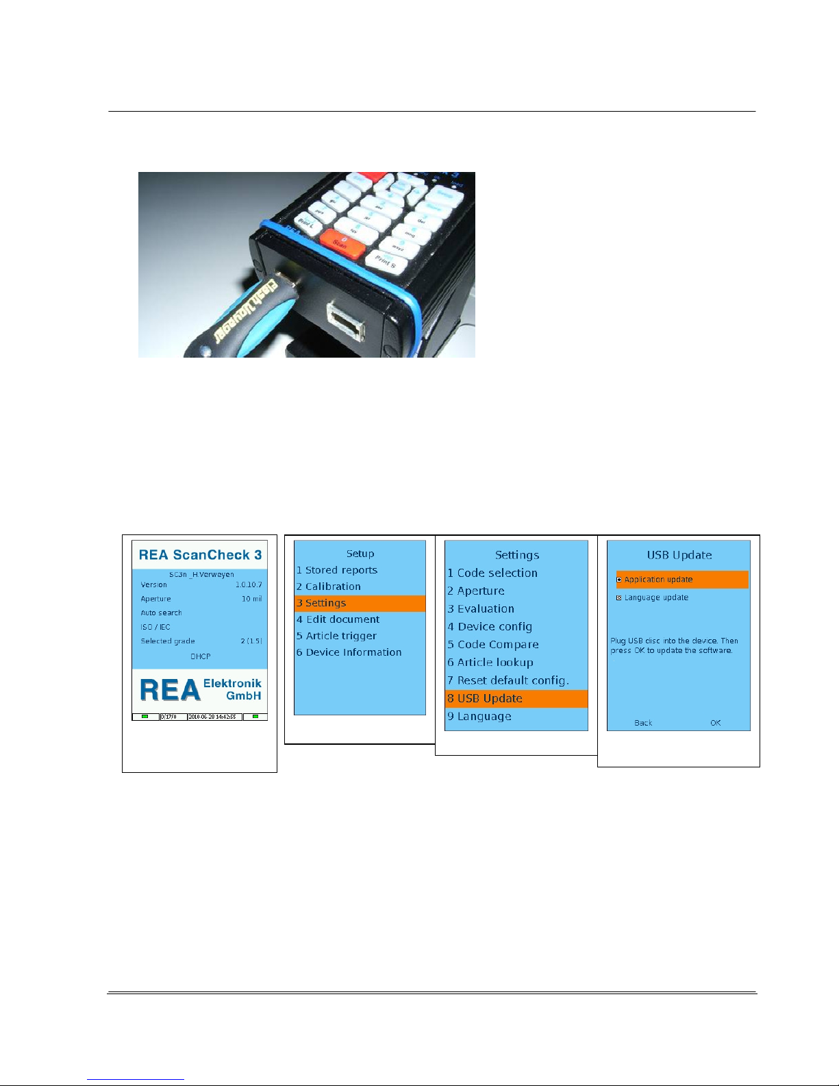
In order to start the update program on the REA ScanCheck 3n, activate the REA ScanCheck 3n with
the <ON> button and wait until the start screen is displayed.
Then select and press the following keys in sequence:
<Setup>, <3> or "Settings", <8>, or "USB Update"
Older versions (GUI below 1.06):
The operating program window must be closed for an update. To do so, press the <ON> button, then press the button <5>.
The program confirms with the message: “Terminate GUI”. After 10 to 15 seconds, the screen turns black and a command line appears. The update
can be started by pressing the button <6> (the 6 appears in the command line). Confirm with the <OK ENTER> button.
The "USB Update" menu page shows a selection of possible update files.
- The field "Application Update" must be selected to update the main program.
- To update the dialogue language files, the "Language Update" field must be selected.
- To update an article database, the "Article Database Update" field must be activated. (This function is
only optional and active after acquiring the corresponding license).
After a short time, the REA ScanCheck 3n starts with the update program.
The graphical interface is closed. The screen turns black and there are no other displays on the screen
for some time. Attention: the update requires approx. 3 to 5 minutes.
The unit then automatically carries out a RESET/restart and then displays the start screen again. The
updated version number should now appear in the version display.
Start screen
Setup
Settings
USB-Update

© REA Elektronik GmbH REA ScanCheck 3 - August 2010
Page 27 of 89
D-64367 Mühltal-Waschenbach
+49 (0) 6154-638 0 www.rea-verifier.de
REA
Elektronik
GmbH
Streamlining • Development • Automation
Electronic Devices and Systems
Attention:
No button may be activated on the unit during the update process. Pressing a button can disrupt the
updating program or even cancel it. The existing operating software may then be defective. The unit no
longer responds. The batteries/rechargeable batteries must be removed from the battery compartment
for a RESET or the unit must be sent back to the manufacturer for repair.
If the update should fail for other reasons, the update program is
interrupted and a corresponding error message is displayed on the
screen.
This must be read and confirmed by pressing the <OK> button.
The unit then goes back to the setup menu screen. An update has
not been carried out, however. If you cannot resolve the error
yourself, the details of the error message should be notated and
the manufacturer contacted.
Return to the main menu with <ESC>.
3.8.2 Updating with the "Update Program" from the
REA CD-ROM
To carry out an update, the PC program must be loaded onto a PC and started. The program required
for this is called UpdateServer.Exe.
It can be downloaded separately from the enclosed CD-ROM to a PC with the Windows operating
system or started from the program REA TransWin32 from the menu bar (see operating instructions of
REA TransWin32 for installation instructions).
To use this software, network communication must be established between REA ScanCheck 3n and
the network interface on the PC. The supplied network cable and the PoE power supply are required
for the connection (see Chapter 2).
Once the program has started, the following screen
appears on the desktop:
The new update file must first be found with the
browse function on the PC and highlighted.
Press the <...> button after the "Update File" field.
The PC file explorer opens. Find the corresponding
directory and select the desired update file
"updatesc3.tgz" by clicking on the right mouse
button.
Confirm by pressing the <Open> button.

© REA Elektronik GmbH REA ScanCheck 3 - August 2010
Page 28 of 89
D-64367 Mühltal-Waschenbach
+49 (0) 6154-638 0 www.rea-verifier.de
REA
Elektronik
GmbH
Streamlining • Development • Automation
Electronic Devices and Systems
The connected REA ScanCheck 3n must now be
selected from the list of possible REA verification
units by selecting it with a click on the left mouse
button.
The REA ScanCheck 3n appears in the list e.g.
with the name "SC3n_PoE-Master." If more than
one unit is listed with the same name, the
individual units can be differentiated by the
different information in the Description column
based on the different serial numbers. Ensure
that you have selected the correct unit and click
the <OK> button for confirmation.
The REA ScanCheck 3n must be activated and
the sleep mode must be deactivated.
Activate the window with the Update Server
program. The selected unit in the unit list is
accepted by pressing the <ADD> button.
The "Update Server" program now looks as
shown at left. By clicking with the left mouse
button on the <Start Update>, the transfer
program can begin transferring the data to the
verification unit.
A progress display shows the progress in percent, from 0-100%. The transfer takes approx.
approx. 20 seconds, during which nothing appears to happen.
Only the label on the <Start Update> button changes to <Stop Update>.
When the data transfer is complete, the progress bar shows "complete" and a message appears that
the update files have been completely transferred. The update program can then be closed by pressing
the "Cancel" button.
After a short time, the REA ScanCheck 3n then
starts with the update program. The light diodes
underneath the display then illuminate in
alternation. The screen then turns black and there
are no additional displays on the screen except for
a command line.
The update requires approx. 3 to 5 minutes.
The unit then automatically restarts and then
displays the start screen again. The updated
version number should now appear in the version
display.
© REA Elektronik GmbH REA ScanCheck 3 - August 2010
Page 29 of 89
D-64367 Mühltal-Waschenbach
+49 (0) 6154-638 0 www.rea-verifier.de
REA
Elektronik
GmbH
Streamlining • Development • Automation
Electronic Devices and Systems
Attention:
No button may be activated on the unit during the update process.
Pressing a button can disrupt the updating program and even cancel it. The existing operating
software may then be defective. If the unit no longer responds, it may need to be sent to the
manufacturer for repair.
Good to know
The unit has the standard factory settings again after an update.
All individual user settings must be made again.
3.9 Calibrating the REA ScanCheck 3n
Attention:
The REA ScanCheck 3n - like any other verification unit - should be recalibrated at regular
intervals of about 4 weeks. If the light conditions change severely, a recalibration must then
also be carried out immediately.
Calibration and measurement under the influence of direct sunlight leads to incorrect
measurement results.
In order to ensure that the unit operates properly and within its specifications, every 4 weeks:
1. carry out a white balance calibration with the white field of the calibration card and
2. measure the reference code (EAN Code 100 %) from the calibration card.
The individual results of the measurements must always lie within the specifications that are specified
in the conformity statement in the appendix of this documentation (see Chapter 3.9.3.1).
A stamped verification report of a measurement of the reference code with calibration card in new
condition is enclosed as a reference measurement. This measurement was created with a REA
reference verification unit: REA reference verification units are in turn regularly calibrated with external
reference standards for the contrast and metric values (by Applied Image, USA).
The calibration card should always be stored protected, may not be contaminated and should not be
touched on its surface. It should be replaced every 1 to 2 years by a new, original REA calibration card.
If the card was previously damaged or dirtied, immediate replacement is required.
Do not calibrate with a photocopy of the original calibration card because the metric and reflective
properties change due to the copying. For the same reason, the calibration card may also not be
laminated. Both would lead to false calibration and faulty measurement results.
Good to know
No extension plate may be installed on the REA ScanCheck 3n during calibration because these
restrict the reading field of the laser beam and falsify the reflection.

© REA Elektronik GmbH REA ScanCheck 3 - August 2010
Page 30 of 89
D-64367 Mühltal-Waschenbach
+49 (0) 6154-638 0 www.rea-verifier.de
REA
Elektronik
GmbH
Streamlining • Development • Automation
Electronic Devices and Systems
3.9.1 Calibrating the REA ScanCheck 3n for 6, 8 and 10 mil Apertures
The calibration process can be selected from the Setup Menu. The key sequence <Setup>,
<Calibration> with the arrow buttons and <OK Enter> or the buttons <Setup> and <2> opens the
Calibration input window.
1. The value printed at lower right on the calibration card used
must be entered in the orange-colored field "reflection factor."
By pressing the <Store> button
or moving the active orangecolored input field with the arrow
buttons to the field OK and then
pressing the <OK ENTER> button, the entered reflection factor
for the white value of the calibration card is accepted into the
unit settings.
2. The REA ScanCheck 3n must be positioned on the marked
unit silhouette on the calibration card as shown in the figure
below so that the illuminated laser beam can pass over the
unprinted white field of the calibration card unhindered.
Pressing <Store> activates the laser beam. Please check
whether the laser beam fully lands in the white field.
3. Pressing the <OK ENTER> button starts the actual calibration
process for the white reflection value.
The laser beam then deactivates when the calibration is
complete. The completed calibration is effective immediately
for the 6, 8 and 10 mil apertures.
Fig.: REA ScanCheck 3n with white value calibration on the calibration
card
Good to know
A special calibration must be made for the use of the 20 mil aperture
(with the additional adapter foot).

© REA Elektronik GmbH REA ScanCheck 3 - August 2010
Page 31 of 89
D-64367 Mühltal-Waschenbach
+49 (0) 6154-638 0 www.rea-verifier.de
REA
Elektronik
GmbH
Streamlining • Development • Automation
Electronic Devices and Systems
4. After the adjustment, the unit reports: Calibration OK.
The calibration process is then complete. By pressing the
<Store> button, the program goes back to
the main screen.
5. The unit can be positioned for measurement in front of the
corresponding EAN -13 sample code for verification tool
monitoring (see Chapter 3.9.3).
3.9.2 Calibrating the REA ScanCheck 3n for 20 mil Aperture
For white value calibration for the measurements with the
20 mil aperture, the 20 mil adapter foot must first be
installed and the operating part moved to the front position
up to the stop.
The unit must then be positioned with its enlarged foot on
the center position in front of the white field of the
calibration card (dashed silhouette) such that the laser
beam illuminates the white surface unhindered.
The calibration steps 1 through 3 according to Chapter
3.9.1 must then be correspondingly repeated.
Figure: REA ScanCheck 3n with 20 mil adapter
A white value calibration is always required if the ambient light conditions have changed.
In order to verify whether white value calibration is required again at other locations, a calibration and
verification tool monitoring is first carried out at the normal unit location.
The verification tool monitoring is then repeated without renewed white value calibration on all other
desired measurement locations. If all measured values for all measurements remain within the desired
tolerances, no recalibration of the white value is required in the future when switching to the other
locations.
A dimensions calibration with the sample code on the calibration card is no longer required with REA
ScanCheck 3n. The unit was already calibrated in the factory to the corresponding size parameters
and adjusted by means of a factory calibration.

© REA Elektronik GmbH REA ScanCheck 3 - August 2010
Page 32 of 89
D-64367 Mühltal-Waschenbach
+49 (0) 6154-638 0 www.rea-verifier.de
REA
Elektronik
GmbH
Streamlining • Development • Automation
Electronic Devices and Systems
3.9.3 Verification Tool Monitoring
Regular monitoring of the verification tool is indispensable in order to ensure that the comparability of
all measurement results. Through regular measurements and comparison of the evaluation results of
measurements of the same reference code sample with the calibrated REA ScanCheck 3n, you can
inspect whether the verification unit is still operating within the specifications indicated by the
manufacturer.
For this purpose, there are two test codes on the REA ScanCheck 3 calibration card that were printed
there with high precision.
The left-hand EAN-13 code, with a nominal size of 100%, should always be used for the verification
tool monitoring. This EAN code must always be calibrated in the same manner with the aperture of
6 mil and under consideration of the handling instructions (see Chapter 4.1). The REA calibration cards
have a serial number on the rear side and are always supplied together with the related REA reference
measurement report that bears the same serial number. The measurement results of the
REA ScanCheck 3n on site must be regularly compared with the measurements of this reference
report. As long as the deviations found in the comparison lie within the specified tolerances, the
following measurements are also comparable within the indicated specifications.
3.9.3.1 Allowable Unit Tolerances
The individual values of the control measurement must each be
compared to one another.
ISO/IEC evaluation, summary
(1st screen of evaluation)
Symbol Good 4/06/670
Code Type EAN13
Code content
4008654123454
ISO/IEC 15416 Parameters (1st screen of the evaluation)
(The values in the diagram are examples; use the reference report)
Parameter % Grade Allowable Tolerance
Decoding 4 Always Grade 4
Symbol contrast 80% 4 +/-8 %
Edge contrast 62% 4 +/-8 %
Modulation 79% 4 +/-8%
Rmin/Rmax 1% 4 +/-8%
Defect: 5% 4 +/-8%
Decodability 87% 4 +/-8%
Optional Parameters (2nd Screen of Evaluation)
Bar Width Deviation Allowable Tolerance Grade
Average Bar Width Deviation: +/- 5% (absolute +/-5 µm) 4
Maximum Bar Width Deviation: +/- 10% (absolute +/-10µm)

© REA Elektronik GmbH REA ScanCheck 3 - August 2010
Page 33 of 89
D-64367 Mühltal-Waschenbach
+49 (0) 6154-638 0 www.rea-verifier.de
REA
Elektronik
GmbH
Streamlining • Development • Automation
Electronic Devices and Systems
Optional Parameters (3rd Screen of Evaluation)
E-value deviation Grade
E-value deviation: +/-20 % (absolute +-10µm), Grade 4
Optional Parameters (4th Screen of Evaluation)
P-value deviation
P-value deviation: +/-20 % (absolute +-10µm), Grade 4
Optional Parameters (5th Screen of Evaluation)
Brightness value Rmax +/-5 %
Dark value Rmin: +/-3 %
Size: 100 % +/- 1 %
(corresponding. Z-Module 330 µm +/- 3.3µm)
In addition, a second measurement of the 200% EAN Code from the
right-hand side of the calibration card can be measured:
Size: 200 % +/- 1 %
(correspond. Z-Module 660 µm +/- 6.6µm).
A size error is only displayed if the measured value is greater than 201%.

© REA Elektronik GmbH REA ScanCheck 3 - August 2010
Page 34 of 89
D-64367 Mühltal-Waschenbach
+49 (0) 6154-638 0 www.rea-verifier.de
REA
Elektronik
GmbH
Streamlining • Development • Automation
Electronic Devices and Systems
4. Operation of the REA ScanCheck 3n
The following chapters describe the operation and correct handling of the REA ScanCheck 3n. It must
always be noted that bar codes are measured and verified with the REA ScanCheck 3n. The
measurement results should therefore be comparable and repeatable. To this end, it is necessary that
all measurements also be carried out under uniform conditions and with a calibrated verification unit.
The reading and lighting angle and distances of the unit to the measured code must primarily always
remain the same.
In bar code reading systems or scanners, this requirement does not apply and can also rarely be
complied with. This is explained by the wholly different purpose of scanners: Scanners should be able
to register bar codes quickly and correctly under the most favorable conditions and provide the
decoded data to the logistic processes.
4.1 Handling of the REA ScanCheck 3
Attention:
Please never hold the unit as shown in the image at lower left. The index finger is touching the
output window of the laser beam.
A) The finger covers the emitting laser beam and
B) The filter pane is dirtied with fingerprints.
Both cause disruptions of the measured light beam which can falsify measurements or even
make them impossible.
Attention: Never put fingers on red light pane Suggestion for correct handling

© REA Elektronik GmbH REA ScanCheck 3 - August 2010
Page 35 of 89
D-64367 Mühltal-Waschenbach
+49 (0) 6154-638 0 www.rea-verifier.de
REA
Elektronik
GmbH
Streamlining • Development • Automation
Electronic Devices and Systems
4.1.1 Instructions for Correct Execution of Code Evaluations
The following procedures must generally be observed when evaluating bar codes so that comparable
and repeatable measurement results are obtained:
1. The laser beam must cross the bar code bars at an angle of 90°.
If this is not the case, the unit indicates bar code sizes incorrectly.
2. The bar code sample must lie flat and even in front of the verification unit. If this is not the
case, the contrast results change. Metallic and glossy materials are particularly critical.
3. The distance to the bar code sample must always remain the same. The ideal distance is
when the REA ScanCheck 3 is in front of the calibration code, exactly as on the calibration card.
4. There should be a free region of about 30 cm in front of the REA ScanCheck.
If there is a bright/dark wall in this region, for example, the contrast results will change.
5. If the ambient light changes, a recalibration must be carried out.
Light changes from light with high ratios of red light/infrared light to light types with low ratios of
red/infrared (e.g. changing from daylight to neon light) are critical.
6. Measurements in direct sunlight are to be avoided because the measurements are falsified.
7. The bar code to be verified should be located centered in front of the REA ScanCheck 3, in
order to obtain the best measurement accuracy (see the positioning help on the calibration card).
8. If there is more than one code in the scanning beam region, then the first code is registered
and measured from the left side by default. It can thus be necessary to cover other codes in
order to be able to center the code to be verified in front of the REA ScanCheck 3.
9. The REA ScanCheck 3n may never be calibrated with extension plates installed, because the
calibration is falsified by the cut-outs in the plates.

© REA Elektronik GmbH REA ScanCheck 3 - August 2010
Page 36 of 89
D-64367 Mühltal-Waschenbach
+49 (0) 6154-638 0 www.rea-verifier.de
REA
Elektronik
GmbH
Streamlining • Development • Automation
Electronic Devices and Systems
4.2 First Measurement of Bar Codes
To measure bar codes, the REA Scan Check 3n must be
calibrated (see Chapter 3.9).
After activation of the REA ScanCheck 3n, the system
requires approx. 15 seconds for initialization of the programs.
Only thereafter does the main screen appear with the
following information:
Name of verification unit: (default: PoE-Master)
Version of operating program (GUI): here 1.0.810.172
Preadjusted aperture: here 8 6 mil
For evaluation of enabled code types:
here automatically searching
Evaluation standard here ISO/IEC 15416
Selected grade according to ISO or ANSI: here 3 (2.5)
Type or address of network connection here DHCP
The left-hand icon in the footer bar indicates green a sufficiently charged battery. If it is colored red,
the charger should be connected immediately. The left-hand number field is only for internal reporting
purposes. The center field displays the system date and time in the form: YYYY-MM-DD hh:mm:ss.
The right-hand icon shows green if the driver program for operation with a PC and with the
REA TransWin32 software is operating correctly. It is colored red if the verifier evaluation program no
longer operates properly and must be restarted.
If a measurement was already carried out with the unit, its
1st evaluation page appears when the <OK ENTER>
button is pressed.
• The laser beam can also be activated as a positioning
aid without starting a measurement. When the laser
beam is lit, the REA ScanCheck 3n must be positioned
so that the laser beam passes over the code
completely and perpendicular to the bar alignment.
• By pressing the digit button <1>, the laser beam can be
activated and deactivated for positioning. A signal tone
sounds.
• A measurement process is started by pressing the red <Scan> button. The laser beam immediately
lights up briefly. The sensor receives the reflected radiation and a signal tone indicates that a
measurement has been completed. The display then shows the 1st overview page of the code
evaluation. All subsequent display pages show detailed results. Page through by pressing the
arrow buttons.

© REA Elektronik GmbH REA ScanCheck 3 - August 2010
Page 37 of 89
D-64367 Mühltal-Waschenbach
+49 (0) 6154-638 0 www.rea-verifier.de
REA
Elektronik
GmbH
Streamlining • Development • Automation
Electronic Devices and Systems
4.2.1 Depiction of a Code Evaluation on the REA ScanCheck 3
4.2.1.1 Quick Display with LED and Acoustic Signaling
The three center LEDs directly underneath the name
represent the measurement results as a quick display with
the colors of a traffic light:
• The red LED fail lights up as an error message if the
selected grade is not reached.
• The green "OK“ LED lights up if the measurement result
has at least reached the selected grade or better.
•
The yellow LED “Warning” lights up in case of a warning message (e.g. if the scan beam was too narrow for
registration of the rest zones)
Corresponding acoustic signals sound in combination with the optical LED displays:
• 1 x tone / green LED on = The measurement was successful and the result is the same or
better than the preset specifications.
• 2 x tones / green and red LEDs off = The measurement was not successful (no or false code symbol
recognized (the unit may not have been set to "automatically
searching code type" or the code symbol is so defective that it
could not be read/decoded).
• 1 x tone plus 2 x tone and red LED on = The measurement and decoding was successful but there is at
least one error in the code symbol so that the preset
specifications cannot be fulfilled.
4.2.1.2 Evaluation of an ISO/IEC 15416 Verification - 1st Screen
Result in the ISO/IEC15416 Format:
Symbol
Evaluation Good or error Grade / Aperture / Wavelength
ScanReflectionProfile: SRP –Grade 0.0
Selected Grade 3 (2.5)
Symbology code content UPC-A
Symbology code content 871866819699
Verification standard and code specification for this evaluation:
Display of the 7 determined ISO/IEC 15416 verification
parameters as bar graphic with measurement value/target value
and the grade thereby attained.
The respective bar is always colored green if the selected grade
is reached or exceeded.
The respective bar is colored red if the selected grade could not
be reached for the parameter.
The poorest grade value of all single parameters determines the
SRP grade of the single evaluation.

© REA Elektronik GmbH REA ScanCheck 3 - August 2010
Page 38 of 89
D-64367 Mühltal-Waschenbach
+49 (0) 6154-638 0 www.rea-verifier.de
REA
Elektronik
GmbH
Streamlining • Development • Automation
Electronic Devices and Systems
4.2.1.3 Evaluation of an ISO/IEC 15416 Verification
- 5th Screen Optional Parameters
The three red asterisks
***
at the upper right indicate that
this evaluation has not yet been saved.
This page shows the measurement results of the optional
parameters (previously also called "traditional evaluation").
Some of these parameters are also classified according to
the setting and are therefore also included in the individual
evaluation of the verification result.
(in the example, PCS ECmin was classified with grade 0,
brightness value (Rs), dark value (Rb) and Z-module with
grade 4)
All other optional parameters were configured before the
evaluation so that these are displayed but area not to be
incorporated in the evaluation.
The settings can be individually changed (see also Chapter
4.6.3.3.15 regarding settings).
4.2.1.3.1 Evaluations of an ISO/IEC 15416 - 6th Screen, Error List
The error list from the measurement results:
All errors of the evaluation are cited in a list.
In this example, the values for the bright zones and for
defects and the verified size relationships on the measured
code are insufficient and lead to devaluation of the total
measurement to grade 0.
Under "03)" a warning is output that the value
ratio with the measured code is too small.
This value only serves for information in the "Display"
presetting and is not included in the evaluation.
(For corresponding settings, see Chapter 4.6.3.3.18)
The three asterisks at the upper right edge of the screen are
always shown on the evaluation pages if this evaluation was
not yet saved locally in the unit.
The arrow keys can be used to page up or down through the individual display pages of the evaluation
views.
The detailed description and interpretation of the individual measurement results and parameters can
be found in the separately available training manual from REA Elektronik GmbH.
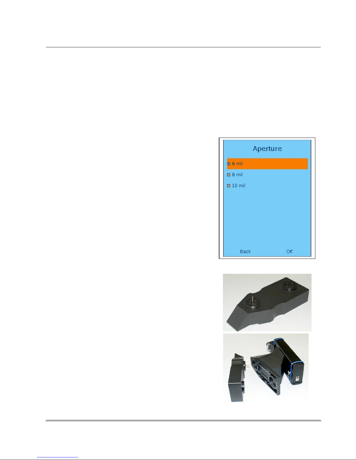
© REA Elektronik GmbH REA ScanCheck 3 - August 2010
Page 39 of 89
D-64367 Mühltal-Waschenbach
+49 (0) 6154-638 0 www.rea-verifier.de
REA
Elektronik
GmbH
Streamlining • Development • Automation
Electronic Devices and Systems
4.3 Adjustments / Selection of the Correct Aperture
The measurement should be made with a compatible aperture for correct code verification. The size of
the aperture should always be smaller than 80% of the X-module size of the subject and is always
indicated in the measurement results. The REA ScanCheck 3n offers code verification with a selection
of four different aperture settings.
The three apertures 6, 8 and 10 mil are always available. The 20 mil aperture is only optionally
available and requires the connection of the mechanical 20 mil adapter foot.
4.3.1 6, 8 and 10 mil Apertures
The function for aperture adjustment is selected in the setup
menu. The currently active input field is highlighted with an
orange-colored bar in all setup menus. The selection can be
moved to the next input field on the screen with the arrow
buttons.
Button sequence:
-
<Setup> button
-
Menu item "3 Settings" and confirm with <OK ENTER> or
press <3> direct.
-
Sub-menu "2 Aperture" press
<OK ENTER> or direct <2>.
-
Select the desired aperture from the Aperture screen with
the arrow control and confirm with <OK ENTER>.
This selects the desired aperture.
-
Activate the <OK> field with the arrow buttons and press
the <OK ENTER> button.
You can also press the <Store> button to save the new
settings.
4.3.2 20 mil Aperture (Option)
Different geometric arrangements for lighting and
measurement window are required for measurements with 20
mil aperture. The REA ScanCheck 3n requires a greater
distance from the code for this purpose. This can be achieved
with the 20 mil adapter, optionally available as an acessory.
The 20 mil adapter is mounted on the base plate of the REA
ScanCheck 3n with snap connectors and an indexing mandrel
as shown without tools and stays affixed there. Only when the
adapter is correctly mounted can the unit be automatically
switched over to the optional 20 mil operating mode.

© REA Elektronik GmbH REA ScanCheck 3 - August 2010
Page 40 of 89
D-64367 Mühltal-Waschenbach
+49 (0) 6154-638 0 www.rea-verifier.de
REA
Elektronik
GmbH
Streamlining • Development • Automation
Electronic Devices and Systems
In addition, the attachment with the operating part must be pushed
all the way forward to the front stop position. Only at the complete
stop is the unit correspondingly changed over to the optional
operating mode. A corresponding error message otherwise occurs.
After correct installation of the adapter and positioning of the
operating part, the REA ScanCheck 3n automatically recognizes
the setting for the "20 mil aperture" and indicates this on the
display. If one of the two presets were not carried out correctly, the
screen shows a corresponding error message: "False Aperture
Setting“.
According to the ISO/IEC 15416 standard, the size of the aperture
may be 80% of the X-module width of the bar code to be
measured at maximum.
The size of the X-module is defined as the average width of the
narrowest element (bar or gap) of the bar code symbol.
The determined value is described as the Z-module.
On the basis of this determination, the X-module width in the code for the selected apertures should
not be smaller than indicated in the following table:
Aperture 6 mil: X>= 187 µm (0.187 mm)
Aperture 8 mil: X>= 250 µm (0.250 mm)
Aperture 10 mil: X>= 312 µm (0.312 mm)
Aperture 20 mil: X >= 625 µm (0.625 mm)
Good to know
1 mm is 1000 µm, 1 µm is 0.001 mm, 1 mil is 25.4 µm or 0.0254 mm.
Code symbols with large X-modules can always be read and verified by an aperture smaller than that
which is allocated. In the reverse, small codes should never be measured with an aperture that is too
large.
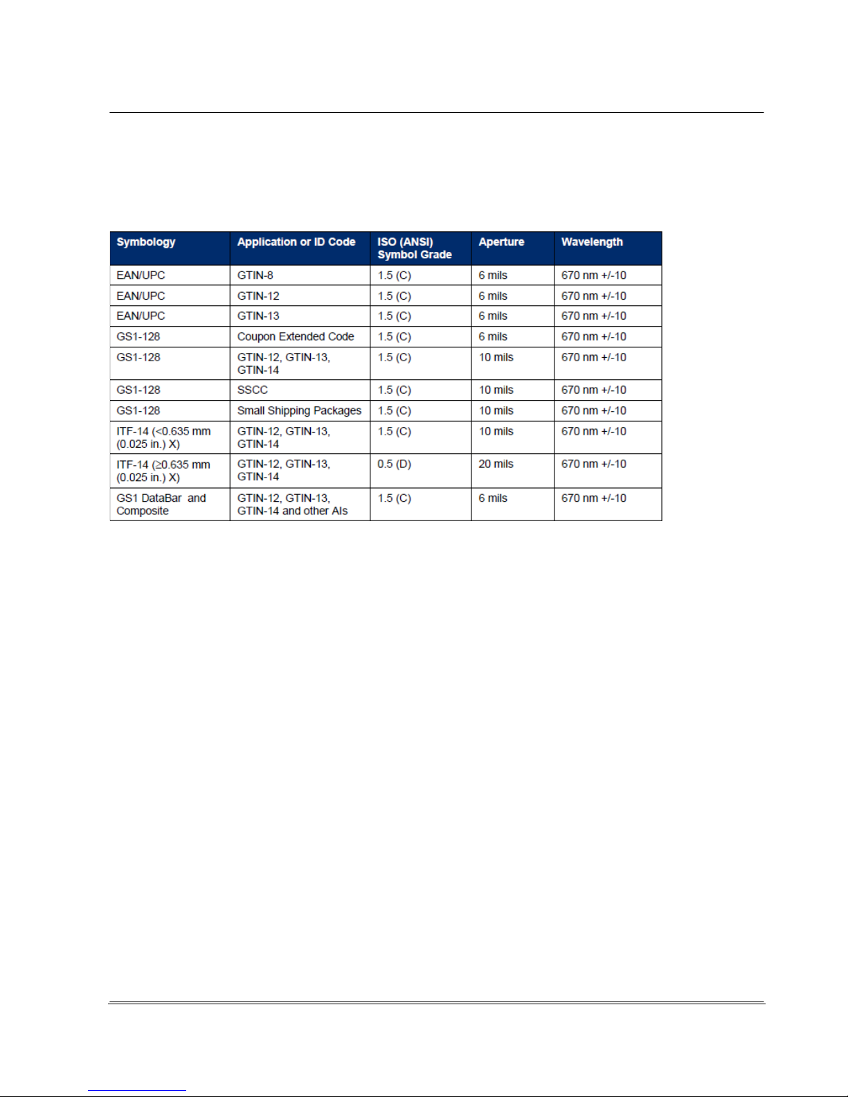
© REA Elektronik GmbH REA ScanCheck 3 - August 2010
Page 41 of 89
D-64367 Mühltal-Waschenbach
+49 (0) 6154-638 0 www.rea-verifier.de
REA
Elektronik
GmbH
Streamlining • Development • Automation
Electronic Devices and Systems
GS1 Global has specified corresponding aperture settings for all GS1 code types in its "General
Specifications" that are to be used for code verification of GS1 codes. (The current version can be
obtained via the GS1 Internet site, see Appendix 5)
Source: Table Copy from the Current Version 10 of the GS1 General Specifications, Chpt. 5.5
In a closed automation application, the aperture can be determined based on the optical aperture of
the bar code scanner used.
The aperture used for code verifications, however, should always be smaller than or at maximum equal
to the scanner aperture.
If the aperture is selected too large, the measurement light point will be wider than the smallest width of
the narrow bar or gap in the code. This causes a worse evaluation for the parameter "edge contrast"
and, consequently, for the parameter "modulation" during a verification.
A smaller aperture remains without effect if the bar code is of good quality. When using smaller
apertures, any defects present have greater effect on the "defects" parameter.

© REA Elektronik GmbH REA ScanCheck 3 - August 2010
Page 42 of 89
D-64367 Mühltal-Waschenbach
+49 (0) 6154-638 0 www.rea-verifier.de
REA
Elektronik
GmbH
Streamlining • Development • Automation
Electronic Devices and Systems
Aperture too large aperture = module width aperture <= 80% of X
Not recommended Maximum size for the aperture
If large codes, such as 100% ITF-14 codes including the bright field zones are measured, it can occur
that the width of the scan beam from the REA ScanCheck 3n is not sufficient in the aperture settings 6,
8 or 10 mil.
In these cases, such codes can only be measured with the large 20 mil aperture.
4.4 Settings / Button Functions / Setup Menu
This chapter describes the functions of the buttons on the keyboard and the menu structures for the
setup functions.
The REA ScanCheck 3n can also be completely configured and controlled remotely from a PC.
The software required for this, REA TransWin32, is available as an option. Some special settings can
only be adjusted via the REA TransWin32 setup function. These special functions are described in the
operating manual for the REA TransWin32 program.
Only functions that can be called up directly on the REA ScanCheck 3n are described here.
4.4.1 General Button Assignments and Operating
Functions
The keyboard of the REA ScanCheck 3n is labeled in multi-color.
The most important buttons are colored red.
Many buttons are allocated with 2 or even 3 different functions.
The different functions are context sensitive; that is, they are called
differently depending on the current screen and the current menu
selection. Interchanging is not possible.

© REA Elektronik GmbH REA ScanCheck 3 - August 2010
Page 43 of 89
D-64367 Mühltal-Waschenbach
+49 (0) 6154-638 0 www.rea-verifier.de
REA
Elektronik
GmbH
Streamlining • Development • Automation
Electronic Devices and Systems
The unit is activated or deactivated with the <ON> button.
If the unit was in sleep mode, this also reactivates it.
The start screen appears upon activating. A menu appears upon deactivating
Arrow button right and arrow button left
-
Move the cursor (selecting the active input field) in all menus and input fields to
the next and previous input field
Arrow button up and arrow button down
- You can page through the 6 screen pages with the arrow buttons when displaying the
measurement evaluation.
- The next input field can be selected and activated for input (the field turns red) in the screen
pages of the Setup menu.
<OK Enter>-button: This can
- Select menus and sub-menu items within them
- Confirm entries in input fields and jump to the next field
- Accept and save inputs of a setup page by selecting the "OK" field on the respective screen
page and pressing the <OK Enter> button again.
<0> to <9> - number buttons enable:
-
the input of the corresponding numbers and letters.
The input of letters functions in the same manner as a mobile
telephone. By pressing a button repeatedly, the selectable digits and
characters appear in the input field in sequence; using the example
button <2>, in the sequence 2 a b c A B C. All other number buttons
use the same pattern.
-
Number button <1>: Activate and deactivate laser as positioning aid
-
Number button <3>: Cancel initiated multiple measurement
<Store> -button: This function is dependent on the respective context:
-
If a measurement result is displayed, pressing this button saves the current
measurement directly to the internal flash memory with the preset file name
format.
-
If you are on the screen pages in the Setup menu, the last selection setting is immediately
accepted and the program jumps back to the higher menu level.
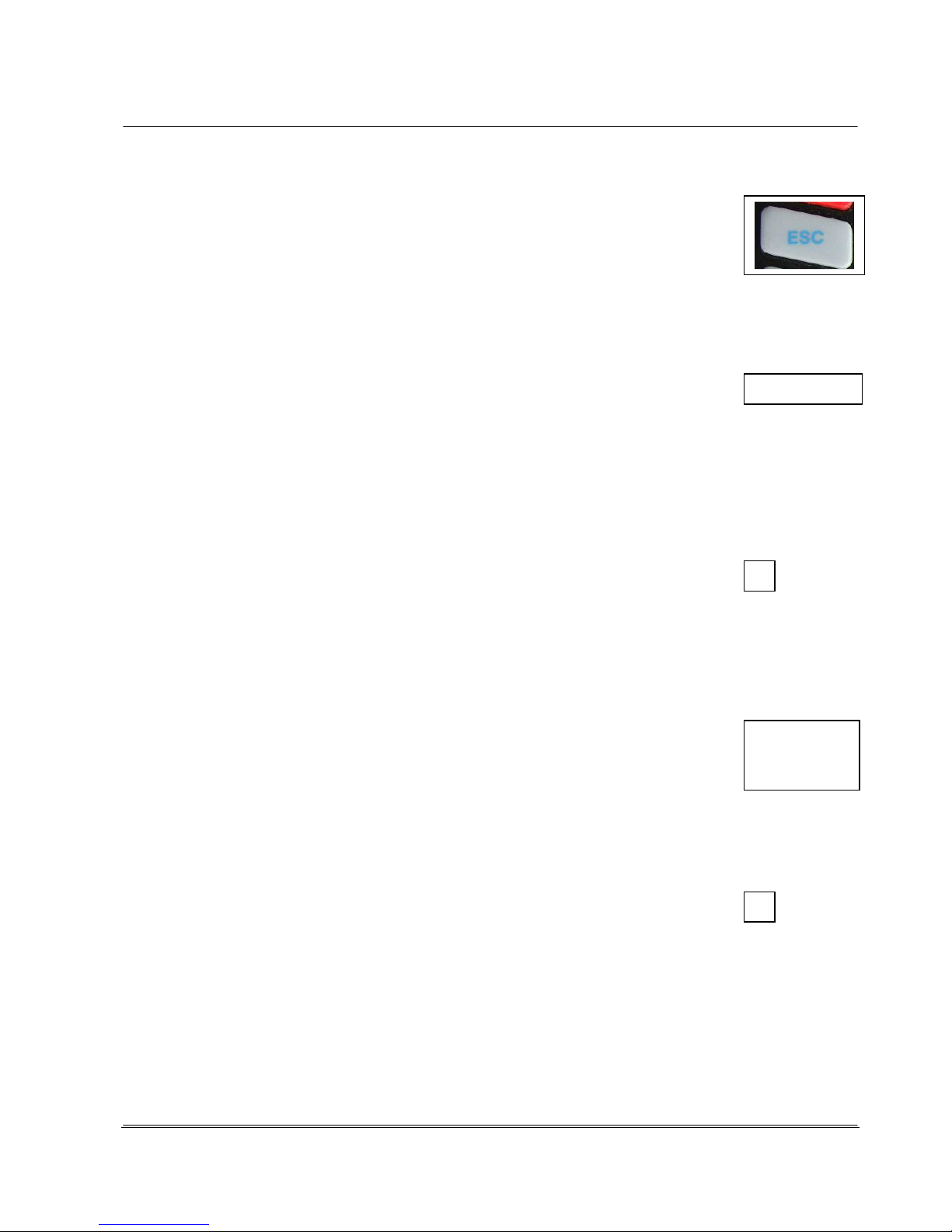
© REA Elektronik GmbH REA ScanCheck 3 - August 2010
Page 44 of 89
D-64367 Mühltal-Waschenbach
+49 (0) 6154-638 0 www.rea-verifier.de
REA
Elektronik
GmbH
Streamlining • Development • Automation
Electronic Devices and Systems
<ESC> -button: With this button
- Entries can be undone.
- You can return to the next higher menu level.
<Setup>- Button:
- This button calls the menu pages for the unit settings (see Chapter 4.6).
<del.>- button: This function is only in the Setup menu and only usable in the
respectively active input window there. It serves to delete the characters in an input
field. After each time the button is pressed, the cursor jumps one position to the left in the activated
(red) input field and deletes the last character.
<Print S> -Button: This function of this button can only be called up
if a measurement result is shown in the display.
If the REA ScanCheck 3n is connected to the REA TD-GPT-U printer, the verification report is printed
on this printer upon activating the "Print" button.
<
> -button: The space button enables the entry of spaces and many other special
characters in the input fields for alpha-numeric inputs.
<Print L> -button: This function of this button can only be called up if a measurement result is shown in
the display. The output takes place in the same manner as in the function <Print S>, but with the
difference that the command for printing the long
version of the measurement report on a connected report printer, type TD-GPT-U, is output.
<Scan>-button: With this button, the user can:
- Start a new bar code measurement if the unit is showing the start screen or
an evaluation screen of a previous measurement.
- enter the number value <0> in an active input field and other special
characters if the unit is in the Setup operating mode.
4.4.2 Buttons with Special Functions
Positioning Aid Function with Laser Beam: Button <1>
Before and during display of a measurement, the laser beam can be activated by pressing
the <1> button without starting a measurement. With the laser beam activated, a
code can
be positioned precisely and centered underneath.

© REA Elektronik GmbH REA ScanCheck 3 - August 2010
Page 45 of 89
D-64367 Mühltal-Waschenbach
+49 (0) 6154-638 0 www.rea-verifier.de
REA
Elektronik
GmbH
Streamlining • Development • Automation
Electronic Devices and Systems
Cancel Function during Multiple Measurements: Button < 3 >
When the unit is in the multiple measurement operating mode, the process can be
cancelled by pressing the button <3> without the specified number of measurements
having to be completely executed.
Article Selection Function for Article Database: Button <5>
(only usable together with the "Article Database32" option
After pressing the button < 5 >, a number sequence from 1-99999999999 can be manually
entered with the number buttons in the following "Article selection" screen and accepted with
<Store>.
The entered number sequence is then compared immediately with
the code contents of the Article Database 32 files loaded in the unit.
If the entered number sequence is found in the article database, the
file contents specified for the display are shown on the display.
If the entered number sequence is not found in the article database,
the "Article not found" error message occurs.
Aperture Selection Function: Button <6> (in preparation)
Before a measurement, the aperture can be quickly changed over from the start screen without going into the menu functions - by pressing the button < 6 > multiple times; the aperture is
switched from 6 mil to 8 mil to 10 mil and then back to 6 mil, for example.
RESET FUNCTION
The unit can be restarted from the ground up
with the reset function. This can be necessary if the
unit no longer responds to the pressing of buttons, the screen
appears to be frozen and the unit cannot be deactivated.
The RESET button is located underneath the battery compartment
directly on the circuit board below. In orderto be able to activate it,
the knurled screw forfastening the battery compartment must be
removed and the battery compartment carefully taken off. There is
a micro-switch with a rubber capat the location indicated on the
diagram. By lightly pressing down with a fingertip or a ballpoint pen tip, you will feel the switch-click
with which a RESET is triggered (see Chapter 4.4.2).

© REA Elektronik GmbH REA ScanCheck 3 - August 2010
Page 46 of 89
D-64367 Mühltal-Waschenbach
+49 (0) 6154-638 0 www.rea-verifier.de
REA
Elektronik
GmbH
Streamlining • Development • Automation
Electronic Devices and Systems
4.5 Setup Menu Structure
The unit is delivered ex factory in a standard configuration and can consequently be used immediately
for verifying most bar codes with standard requirements. The REA ScanCheck 3n also has adjustment
menus for extensive individual settings of all unit parameters, however. All adjustment functions can be
called up by pressing the <Setup> button. If the REA ScanCheck 3n is operated with the optionally
available PC software REA TransWin32, the complete configuration can also be made from the PC via
corresponding windows and also saved in the future as a complete preset profile in a profile manager
or called up from there.
4.6 Setup Main Menu "Configuration" with 6 Sub-Menus
The start screen for the Setup menu is displayed after pressing the
<Setup> button.
In the current version, 6 different menu items are shown for
selection. The menu items selected with the cursor/arrow buttons
are highlighted in color. The selection can be moved up and down
by pressing the arrow buttons.
All menu items each have additional sub-menus for the
corresponding settings. Each sub-menu can in turn be selected by
activating the desired menu with the arrow buttons and selecting
with the <OK Enter> button.
The number button can also be activated directly with the number
in front of the desired menu item. The program then jumps
immediately to the corresponding sub-menu window.
Here, button <1>
4.6.1 Setup Sub-Menu 1 - Measurement Archive
This archive shows the listing of all measurement results previously saved in the unit.
The saved measurement reports are saved on an internal, reset- proof MMC memory card with
a capacity of 512 MB.
A measurement report can be selected by positioning the color highlighting on the desired file with the
arrow buttons and then pressing the <OK Enter> button.
All listed files can be selected with <Select all>.
All listed files can be set back to not selected with <Select none>.
Depending on the selected preset for the print output, the selected measurement report is either sent
to the interface for the REA TD-GPT-U report printer by pressing the buttons
© REA Elektronik GmbH REA ScanCheck 3 - August 2010
Page 47 of 89
D-64367 Mühltal-Waschenbach
+49 (0) 6154-638 0 www.rea-verifier.de
REA
Elektronik
GmbH
Streamlining • Development • Automation
Electronic Devices and Systems
<Print (L)> or <Print (S)>.
Alternatively, the selected measurement report is displayed in the PC software REA TransWin32.
<Open> Displays the topmost of all highlighted measurement reports on the display of the REA
ScanCheck 3n.
<Delete> Deletes all selected files
If a great many reports are saved, this can heavily reduce the response time of the unit.
4.6.2 Setup Sub-Menu 2 Calibration
Due to its importance, the calibration function is described in a previous chapter (see Chapter 3.9).
4.6.3 Setup Sub-Menu 3 Settings with 9 Additional Sub-Menus
The selection menu for the unit settings
can be selected by pressing the button
<3> or positioning the colored highlight on
the "Settings" field with the arrow buttons
and pressing the <OK ENTER> button.
This opens the "Settings" sub-menu with
an additional 9 sub-menus in which all
settings for operating mode and
evaluation method can be changed. All
changes to the standard presets should
always be made with caution.
4.6.3.1 Setup Sub-Menu 3 Settings - Sub-Menu 1 Code Type Selection - Code Type
Tables
In this menu, groups of code symbologies or individual code types can be selected for
verification/evaluation. The properties of the respective code types that are to be verified can
additionally be configured. Entering the code selection enables 3 fundamentally different presets.
The Code type search automatic selection is the simplest setting. It comprises the automatic
recognition of common code types. This summary covers most application cases and is permanently
specified by REA. It cannot be changed by the user.
The selected code selection is accepted by selecting <OK>. By selecting <Continue>, the list of preset
code types and parameters is displayed.

© REA Elektronik GmbH REA ScanCheck 3 - August 2010
Page 48 of 89
D-64367 Mühltal-Waschenbach
+49 (0) 6154-638 0 www.rea-verifier.de
REA
Elektronik
GmbH
Streamlining • Development • Automation
Electronic Devices and Systems
The Code type search individual selection enables the compilation of a code type list as the user
individually desires it. It includes the automatic recognition of all individually compiled code types.
The existing code selection is accepted by selecting <OK>.
By selecting <Continue>, the list of preset code types and parameters is displayed and can be
changed. The compilation of this list upon delivery is identical to the default setting and can be
changed by the user at any time.
The single code search selection enables the selection of a single code family or a single code type.
This ensures that only the one activated code is verified and evaluated. All other codes produce an
error message.
The existing code selection is accepted by selecting <OK>.
By selecting <Continue>, the list of available code types is displayed.
In the case of all code types that are not selected, the verification unit produces the error: "Not
decodable."
The "single code search" operating mode must be used for verification of code types that may not be
decoded in combination together with other code types.
This the case for the following codes, for example: "Mini Pharma Code“ and "Pharma Code“.
The "single code search" is recommended for the code type "Stacked GS1 DataBar Code."
Settings in the User Search menu do not change any settings in the other two selection menus.
When decoding all other non-selected code types, the unit produces this error message upon a
verification: "Not decodable."

© REA Elektronik GmbH REA ScanCheck 3 - August 2010
Page 49 of 89
D-64367 Mühltal-Waschenbach
+49 (0) 6154-638 0 www.rea-verifier.de
REA
Elektronik
GmbH
Streamlining • Development • Automation
Electronic Devices and Systems
4.6.3.1.1 Code Selection
The code types can be selected from the list appearing in the display.
To do so, the red activation field is moved over the list entries with the arrow buttons.
When a code is thus highlighted, its selection or deselection can be made with the <OK Enter> button.
Upon selecting, a cross is drawn in the empty box. The background color also changes from blue to
green.
Once all desired codes have been activated from the list, go to the OK field in the footer with the arrow
buttons and confirm with <OK ENTER>.
The list of the selectable code types has a different length depending on whether the "optional code
types" were purchased as an accessory in addition to the standard code list.
The left image shows the 1st page code list The right image shows the 2nd page with the optional code types.
These two figures show the code list without optional code types. The left image shows the screen
immediately after selection. The right image shows the display when the cursor is at the end of the list.
The gray scrollbar on the right screen page shows the position in the list.
A code type can be activated or deactivated by positioning the cursor on the desired code type and
pressing the <OK Enter> button.
Some codes cannot be activated together with other codes (e.g. Code ITF-14 cannot be selected
together with Code 2 from 5 INT). If such a code type is selected, the incompatible code type is
automatically deselected.

© REA Elektronik GmbH REA ScanCheck 3 - August 2010
Page 50 of 89
D-64367 Mühltal-Waschenbach
+49 (0) 6154-638 0 www.rea-verifier.de
REA
Elektronik
GmbH
Streamlining • Development • Automation
Electronic Devices and Systems
4.6.3.2 Setup Sub-Menu 3 Settings - 1 Code Type Selection - Additional Verification
Criteria
Some codes offer the option of incorporating additional verification criteria (e.g. for structure
and size) into the verification. Such codes are supplied with a "+" sign in front of the selection box in
the code table.
This is done by pressing the <Setup> button again.
The individual criteria are described in the following chapters.
If the code type does not enable any selectable additional verifications, the right screen message
appears.
4.6.3.2.1 The EAN / UPC Code Family
4.6.3.2.2 EAN-13 - Additional Verification Criteria
According to the GS1 General Specifications, EAN-13 codes are used in various application areas
but primarily in retail.
In retail, the GTIN ® (Global Trade Item Number®) is shown with the EAN-13. Additional applications
are in goods distribution centers and also within store chains when required.
The code size of the EAN-13 can vary between 80% (module width 0.264 mm) and 200%
(module width 0.66 mm) for the "Retail" field. This is also the
factory preset for code size
verification.
If the EAN-13 is used in goods distribution, it is assumed that it will also be used simultaneously in
retail. For that reason, the code size must be permissible for both application areas.
This reduces the allowable code size in the "General retail" field to values between 150% (module
size 0.495 mm) and 200%.
In the case of "On demand," labels are printed for company-internal applications on site in the store.
Due to the low resolution of thermal printers (typically 200-300 dpi) and due to the normally narrow
label sizes used in this application, codes with a size from 75% (module widths from 0.250 mm) are
also permitted. This applies only for the GS1 General Specifications, however.
The ISO/IEC standard 15420 does not permit this size reduction.
An EAN-13 code can be expanded with an additional code 2 from 5. This "Add On Code" is used for
example in Germany to identify the different editions of daily newspapers and magazines. One can
thereby always use the same article number for a product - a publication, in this case - but still
differentiate the editions clearly from one another with differing add on numbers.

© REA Elektronik GmbH REA ScanCheck 3 - August 2010
Page 51 of 89
D-64367 Mühltal-Waschenbach
+49 (0) 6154-638 0 www.rea-verifier.de
REA
Elektronik
GmbH
Streamlining • Development • Automation
Electronic Devices and Systems
So-called instore codes - codes for company-internal application - are frequently used together with
print on demand settings. Such instore codes code the article number of retail products together with
a price or weight indicator. This procedure makes it possible to calculate products via scanner
checkout that are sold by weight or quantity (meat, cold cuts, cheese or fruits).
The specifications for the instore code with the ADD ON Code enable the optional application of a
second verification number for the variable file content on weight or price.
The instore selection is only possible with EAN-13 and UPC-A codes. By definition, an instore code is
only valid within a company. An instore code is uniquely identified by the first digit "2" in the code. This
also applies for the UPC-A code. If a UPC-A code is decoded as an EAN code, the UPC-A code then
only has 13 characters. The 13th character is always "0." An instore code in UPC-A symbology is
identified by the character sequence "02" at the start.
If the instore function is activated, a verification on a UPC-A code always takes place on the 2nd
character.
The following screen appears after selecting the instore selection menu:
Only the length for the price or weight field is specified in this table according to the required standard.
These settings are required because GS1 US (previously UC Council) specifies 4-digit Add On.
GS1 Global, by way of contrast, specifies a 5-digit Add On.
The instore verification function of the REA ScanCheck 3n is flexible and allows for the combination of
all settings. The table lists all coding possibilities from "20" to "29."
The country organizations output partially individualized specifications and recommendations for the
use of single instore code types. It can be that several combinations are not sensible and cannot be
used.
Control the cursor position with the arrow buttons to the desired input field. If <OK Enter> is activated
now, the entry changes from "not activated" to "activated" with the "•" in the box, or the reverse.
You can select between "NO," "EAN" and "UPC."
If "NO" is selected, the second verification character is not evaluated.
If "EAN" is selected, a 5-digit price or weight indicator is expected and verified.
If "UPC" is selected, a 4-digit price or weight indicator is expected and verified.
The code structure is shown in the following table:
Character: 1 2 3 4 5 6 7 8 9 10 11 12 13
UPC
P P N N N N N P2 PG PG PG PG CD
EAN
P P N N N N P2 PG PG PG PG PG CD
OFF
P P N N N N N N N N N N CD
P - Prefix (see list with settings) N - Article number P2 - 2nd verification
character

© REA Elektronik GmbH REA ScanCheck 3 - August 2010
Page 52 of 89
D-64367 Mühltal-Waschenbach
+49 (0) 6154-638 0 www.rea-verifier.de
REA
Elektronik
GmbH
Streamlining • Development • Automation
Electronic Devices and Systems
PG - Price or weight CD - Symbol verification character check
Each single or double letter represents a character in the code.
Please note that the designations JAN Code and IAN Code are just different names for the EAN Code.
4.6.3.2.3 UPC-A Code - Additional Verification Criteria
The UPC-A code is the forerunner of the EAN code. It allows the encoding of 12 characters.
The EAN-13 Code, developed later, enables the expansion of the encryption to 13
characters.
The foremost goal in doing so was to ensure compatibility of both code types. By introducing a new
character set for the left code half, it was possible to encrypt the 13th character there in the 6
characters. The value of the 13th character is determined from the change of character set for the left
code half. If there is no change in the character set (character set A), this is always a UPC-A code. If it
is decoded as a 13-character code, the 13th character is always the "0" for a UPC-A code. If the code
is encrypted as an EAN code, the 13th character must always consist of the characters 1 through 9
and never "0."
The properties and meaning of the properties are identical with those of the EAN 13 Code.
If used as instore code, it is specified that the 12th character must have the value "2." If the UPC-A
code is decoded with all 13 characters, the leading character "2" must always be decoded as "02."
The REA ScanCheck 3n decodes the complete information with 13 places. For that reason, the leading
character in the left screen is shown with "02" instead of "2."
This takes into consideration that the UPC code in application as instore code always has only one
prefix character. All other details are identical to the description of the properties of the EAN -13 Code
(see Chapter 4.6.3.2.2).
4.6.3.2.4 EAN-8 Code - Additional Verification Criteria
The EAN-8 Code is a short version of the EAN-13 / UPC-A Code, but with 8 characters
instead of 13 or 12. It is intended particularly for
use on small products.
The content of the properties is identical to that of the EAN -13 Code (see also Chapter 4.6.3.2.2).
In the case of the EAN-8 Coide, however, no Add Ons are permitted as in the case of EAN-13 and
UPC-A Code.
Furthermore, the EAN-8 instore code always represents only one fixed article number.
A variable attachment for price or weight indicators is not specified.
For such requirements, the EAN-13 Code or UPC-A Code must be used.

© REA Elektronik GmbH REA ScanCheck 3 - August 2010
Page 53 of 89
D-64367 Mühltal-Waschenbach
+49 (0) 6154-638 0 www.rea-verifier.de
REA
Elektronik
GmbH
Streamlining • Development • Automation
Electronic Devices and Systems
4.6.3.2.5 UPC-E Code - Additional Verification Criteria
The UPC-E Code is a reduced version of the UPC-A Code. The EAN 8 Code always contains only 8
characters. If a decoder is adjusted accordingly, such a code can be extended by the corresponding
number of zeroes in order to obtain a 13-digit EAN-13 Code from the EAN 8 Code.
In the UPC-E symbology, the extension from 6 characters to 12 characters is already incorporated in
the decoding algorithm. A conventional bar code scanner will always be able to display and evaluate
the code format of a normal 12-place UPC-A Code extended to 12 characters when a 6-place UPC-E
Code is read.
REA bar code verification units always display only the actual 6 decoded characters of the code. Later
versions will display the code extended to 12 characters.
The meaning of the properties is identical to that in EAN-13 Code. In contrast to the EAN-8 Code, the
UPC-E Code allows the attachment of an Add On code.
The factory preset is: "Retail" and "no add-on."

© REA Elektronik GmbH REA ScanCheck 3 - August 2010
Page 54 of 89
D-64367 Mühltal-Waschenbach
+49 (0) 6154-638 0 www.rea-verifier.de
REA
Elektronik
GmbH
Streamlining • Development • Automation
Electronic Devices and Systems
4.6.3.3 The Code 128 Family
4.6.3.3.1 GS1-128 - Additional Verification Criteria
The GS1-128 Code (previously EAN 128) is a special form of Code 128 in which a special data
structure is applied. This was specified by the GS1 Global organization. The REA ScanCheck 3n can
also verify these special data structures and several additional properties of this code type.
According to the GS1 specifications, the allowable module size - according to the
respective application areas - can be limited.
The standard setting is the group "All sizes" with a permitted module width of 0.495 mm to 1.016 mm.
The other two size settings can each be arranged in the case of bilateral agreements and companyinternal applications.
The activation of the structure verification enables the expansion
of the code verification to compliance with the data structures specified by GS1. The standard preset is
the incorporation of the verification. <EAN> is activated. In some special cases of company-internal
application, the structural verification does not make sense under certain circumstances and can be
deactivated here. Adjustment <No> activated.
4.6.3.3.1.1 Verification of Application Identifier
The GS1 specifications also provide for the use of five application identifiers (AI):
(11) Date of production (YYMMDD)
(12) Due date for an amount on a receipt
(13) Packaging date (YYMMDD)
(15) Best before date (YYMMDD)
(17) Maximum best before date or date of expiration (YYMMDD)
If this data is to be verified for compliance, the data verification can
be activated by marking the box. If the data verification is not
activated, only the correct format within the code data structure is
verified, not compliance with the data overruns.
The identifiers AI 11 and AI 13 have a positive and a negative
offset. Identifiers AI 12, 15 and AI 17 have only two positive
offsets. There it is possible to enter an upper and a lower date
value in the future (see example below).

© REA Elektronik GmbH REA ScanCheck 3 - August 2010
Page 55 of 89
D-64367 Mühltal-Waschenbach
+49 (0) 6154-638 0 www.rea-verifier.de
REA
Elektronik
GmbH
Streamlining • Development • Automation
Electronic Devices and Systems
The allowable period is verified for the selected GS1-128 application identifier (AI).
By activating the <OK> field, the selected settings for the respective AI identifier are accepted and
saved and the sub-menu for selection of an AI identifier is displayed again. This can be closed at any
time by pressing the <ESC> button.
Any previously entered settings are not accepted when doing so.
Example (Entries for the Application Identifiers 11 and 13)
The current date is December 01, 2010.
The selected area in the "GS1-128 Settings" could then be selected as follows:
OFFSET
From - 0010 Days
To + 0020 Days
The allowed range is then from Nov. 21, 2010 to Dec. 21, 2010.
(11)101222 Production date Dec. 22, 2010
In verification this date creates an error message.
(11)101121 Production date Nov. 21, 2010
In verification this date does not create an error message because it is still within the specified period.
Example (Entries for the Application Identifier 15 and 17)
Selected time period according to the current date of the internal clock of the REA ScanCheck 3:
From + 0020 Days
To + 0030 Days
The permissible time period goes from Dec. 21, 2010 to Dec. 31, 2010 in dependence on a current
date, December 01, 2010.
(15)101205 Best by date Dec. 05, period exceeded, error message
(15)101221 Best by date Dec. 21, No error, within period
(15)101231 Best by date Dec. 31, No error, within period
(15)110102 Best by date Jan. 02, 2011, Error, period exceeded
The relative indication of the valid date range described here was selected in order to prevent a daily
adjustment of the date limits.

© REA Elektronik GmbH REA ScanCheck 3 - August 2010
Page 56 of 89
D-64367 Mühltal-Waschenbach
+49 (0) 6154-638 0 www.rea-verifier.de
REA
Elektronik
GmbH
Streamlining • Development • Automation
Electronic Devices and Systems
4.6.3.3.2 The GS1 DataBar Code Family
4.6.3.3.3 RSS / GS1 DataBar Code - Additional Verification Criteria
The GS1 DataBar Code (previously called RSS Code) is a new
code symbology. It was developed between 1995 and 2000. In
contrast to the previously disseminated code types, whole data
words are encrypted in GS1 DataBar Codes and not just
encrypted character for character in the bar code symbols. For
that reason there is no longer any option to decrypt the respective
character content from the individual code words. This type of
encryption is more efficient than the classical linear bar code types
and leads to smaller space requirements for the depiction of code
characters.
RSS is the abbreviation for the description "Reduced Space
Symbology." Due to the possible mix-up of the name with
"RSS feeds" - known from the Internet - GS1 decided to change
the name to GS1 DataBar.
The variant GS1 DataBar Expanded offers the greatest possible
flexibility of this code type. The GS1-128 data structures known
from the Code 128 can be completely encrypted in the same manner. Exactly as in Code 128,
however, other data structures can also be encrypted in GS1 DataBar Expanded (or RSS Expanded).
For that reason there is a settings menu in which the verification of the GS1 128 data structure can be
activated or deactivated.
4.6.3.3.4 The Code 39 Family
4.6.3.3.5 Code 39 - Additional Verification Criteria
Code 39 is an old symbology with which up to 43 diferent characters can be encrypted.
It requires comparably as much space for this. It continues to be used in many applications in
the industrial field.
With the selection of the ANSI function, the verification of the ratio between narrow and wide code
elements is converted from the ratio values specified by the ISO standard to the values specified in the
ANSI standard. ANSI allows a ratio from 1:2.5 to 1:3.0 if the module width equals less than 0.5 mm.
The ISO standard always allows a ratio between 1:2.0 and 1:3.0.
Upon activation of the verification character function, a verification character verification is made on
standard code 39. The verification character can be thereby verified according to Modulo 10 or Modulo
43. If this function is not activated, no verification character verification is made.
If the UPU or HIBC functions were activated, deactivation of the verification character function has no
meaning because a verification character control is always specified and contained in these code
types.

© REA Elektronik GmbH REA ScanCheck 3 - August 2010
Page 57 of 89
D-64367 Mühltal-Waschenbach
+49 (0) 6154-638 0 www.rea-verifier.de
REA
Elektronik
GmbH
Streamlining • Development • Automation
Electronic Devices and Systems
Codes can also be verified without a structural verification. To do so, the field "No" is activated in the
structural verification selection. This is also the factory setting.
HIBC is the abbreviation for "Health Industry Bar Code." HIBC describes a standard for a special
application of a service provider, first of all, and second of all a standard for identification in a supplier
label for the healthcare industry.
In both cases, the HIBC code begins with a "+" character, followed by a specified data structure.
The REA ScanCheck 3n verifies whether the "+" character exists and whether the verification character
is correct.
It is planned that later software versions will also additionally verify the data structure.
In the case of Code 39 in postal applications, it is advisable under certain circumstances to activate the
UPU verification (Universal Postal Union).
The 1st and 2nd characters of the code serve as an indicator of the related postal service. With
verification activated, it is determined whether the value is permissible.
The 3rd to 10th characters form a serial number. In the verification it is determined whether 8
characters are included and the first character is numerical.
The 11th character is a verification character formed according to Modulo 11.
In verification it is determined whether this character is correct.
The 12th and 13th characters form the ISO country code with which the origin of the shipment is
specified. It is verified whether the country code is valid.
4.6.3.3.6 Code 39 – Full ASCII - Additional Verification Criteria
Code 39 Full ASCII
The selection of Full ASCII changes the decoder to Full ASCII mode. Additional small
letters and special characters are encrypted therein with code character pairs. Small
letters and special characters are only decrypted and depicted upon decoding if this code type is
selected.
With selection of the ANSI function, the verification of the ratio between the narrow and wide code
elements is converted from the ratio values specified in the ISO standard to the values specified in the
ANSI standard. ANSI allows a ratio from 1:2.5 to 1:3.0 if the module width equals less than 0.5 mm.
The ISO standard always allows a ratio between 1:2.0 and 1:3.0.
Upon activation of the verification character function, a verification character verification is made on
standard code 39. The verification character is thereby verified according to Modulo 43. If this function
is not activated, no verification character verification is made.
4.6.3.3.7 PZN Codes - Additional Verification Criteria
PZN Code uses the normal Code 39 symbology, but with several restrictions. With the PZN Code, a
pharmaceutical article number is depicted for use in retail pharmacies. PZN is the abbreviation for
‘Pharma Zentral Nummer’ (Pharma Central Number).
Verification of the verification character is specified as mandatory and cannot be deactivated.
The PZN Code always stars with a "*" as an initial character, followed by a dash "-" and followed by a

© REA Elektronik GmbH REA ScanCheck 3 - August 2010
Page 58 of 89
D-64367 Mühltal-Waschenbach
+49 (0) 6154-638 0 www.rea-verifier.de
REA
Elektronik
GmbH
Streamlining • Development • Automation
Electronic Devices and Systems
six-digit character sequence as well as a verification character.
This verification character is just calculated from the 6 previous characters without the dash. The code
always concludes with a "*" as a stop character.
The ratio (the relationship of narrow to wide bars) is indicated at 1:2.5 in the nominal and is permitted
and verified with a tolerance from 1:2.0 to 1:3.0.
The specification for verification of PZN codes furthermore requires a light source with red light and
with a wavelength of 670 nm. For this reason, it is urgently advised to use only color combinations that
can also be easily read by red light scanners (630 nm to 680 nm). The REA ScanCheck 3n always
uses a laser light source with a wavelength of 670 nm. The aperture should equal 6 mil. The code size
X is permissible between 0.187 mm and 0.450 mm. In the nominal size of a PZN Code with a module
size of X=0.25 mm, a minimum code height of 8 to 20 mm is required. The text "PZN" must always be
indicated in the plain text line but may never be encoded in the bar code.
4.6.3.3.8 Codabar - Additional Verification Criteria (Optional)
Codabar is a very old code symbology that is used in the pharmaceutical industry
and in photography labs. It is no longer current and should not be used for new applications.
Codabar can use a verification character but does not have to.
The verification character is formed according to Modulo 11 and verified by REA ScanCheck 3n if the
selection box is activated.
With the ANSI selection box, size ratios between the narrow and wide bars between 1:2.5 and 1:3.0
are permitted if the module width is under 0.5 mm. The ISO standard allows ratios between narrow and
wide bars of 1:2 to 1:3 in any case without the restrictions as with ANSI.

© REA Elektronik GmbH REA ScanCheck 3 - August 2010
Page 59 of 89
D-64367 Mühltal-Waschenbach
+49 (0) 6154-638 0 www.rea-verifier.de
REA
Elektronik
GmbH
Streamlining • Development • Automation
Electronic Devices and Systems
4.6.3.3.9 ITF-14 Code - Additional Verification Criteria
ITF-14 Code is a special form of 2/5 Interleaved Code with several additional restrictions and
specifications and GS1 data structure.
A bar code reader cannot automatically differentiate between these two code types. For that reason,
only one or the other code type can be activated in the presets (either 2/5i or ITF-14).
In the GS1 General Specifications, the allowable size ranges for ITF-14 codes are specified - identical
to those in the cast of GS1-128 Code. Correspondingly, there are also three different application areas
for this code type with different allowable code sizes:
Internal logistics (X-module widths from 0.25 mm to 0.495 mm)
General distribution (X-module widths from 0.495 to 1.016 mm)
All Sizes (X-module widths from 0.25 mm to 1.016 mm)
The targets and thresholds are identical to those of Code GS1-128.
The factory preset for the additional verification criteria is "General distribution."
ITF-14 Code normally encodes the GTIN with a leading 14th character.
4.6.3.3.10 2/5i Code - Additional Verification Criteria
2/5i Code was developed in order to obtain codes with a higher
coding density; that is, many characters in a small space.
For this reason, this code type continues to find wide use.
With activation of the selection box "verification character," verification of the verification character
according to Modulo 10 or for the bill of lading of the German Postal Service is activated.
With selection of the 'ANSI' box, the ratio verification switches back and forth from the ISO standard to
the ANSI standard.
In the case of ANSI, size ratios between the narrow and wide bars between 1:2.5 and 1:3.0 are
permitted if the module width is under 0.5 mm.
The ISO standard allows ratios of 1:2 to 1:3 in any case and without the restrictions as with ANSI.
This code can only be selected if ITF-14 Code is not activated (see above).

© REA Elektronik GmbH REA ScanCheck 3 - August 2010
Page 60 of 89
D-64367 Mühltal-Waschenbach
+49 (0) 6154-638 0 www.rea-verifier.de
REA
Elektronik
GmbH
Streamlining • Development • Automation
Electronic Devices and Systems
4.6.3.3.11 Plessey Code - Additional Verification Criteria (Not Yet Available in the
Current Version)
Plessey Code is a purely binary code type and was defined in
1971. It is used today particularly in library applications. Plessey
Code and MSI Code are similar code types, whereby Plessey
Code uses different start and stop characters and contains 6
additional characters.
Plessey Code allows for three different sizes with the following
nominal character distances:
0.635 mm (narrow), 0.787 mm (medium) and 1.02 mm (large).
If "automatic" is selected, the REA ScanCheck 3n calculates
the deviation to the next standard size.
The use of two different stop characters is permitted for Plessey
Code: One is used if the code may only be read from left to right.
The other is used if the code is approved for bidirectional reading.
4.6.3.3.12 MSI Code - Additional Verification Criteria
MSI Code is a purely binary code type and is used in the
BeNeLux countries for encoding article numbers in the
pharmaceutical field.
Plessey Code and MSI Code are similar code types.
MSI Code is purely numerical. Each character consists of 4 binary
elements. The coding is comprised of the start character and up to
15 utility characters, one or two verification characters and a stop
character.
The size definition of the MSI Code can be made as module width.
Plessey Code does not permit this and can only use a "pitch" as
size information.

© REA Elektronik GmbH REA ScanCheck 3 - August 2010
Page 61 of 89
D-64367 Mühltal-Waschenbach
+49 (0) 6154-638 0 www.rea-verifier.de
REA
Elektronik
GmbH
Streamlining • Development • Automation
Electronic Devices and Systems
4.6.3.3.13 Pharma and Mini Pharma Code - Additional Verification Criteria
Pharma Code is a purely binary code that uses no start or stop characters. It is also
described as binary code, Laetus Code, Sick Code or Weber Code.
REA bar code verification units use the specifications of the Laetus company for verifying Pharma
Codes.
The specifications of other manufacturers are slightly different (e.g. the Sick Code).
The decode value of this code type is different depending on whether the code is read from left to right
or from right to left. Left to right is specified as the standard reading direction. This also corresponds to
the factory preset in the REA ScanCheck 3.
If the read direction should be reversed, the "Use non-standard read direction" must be activated. This
can be useful in cases where the subject cannot be turned around for a reading.
Pharma Code knows only two sizes. Standard has a module width of 0.5 mm and Mini Pharma Code
0.35 mm. The "always automatic" setting attempts to determine the correct size automatically.
4.6.3.3.14 Setup Menu 3 Settings - 2 Aperture
The aperture setting is very important for correct measurement (see also Chapter 4.3).
4.6.3.3.15 Setup Menu 3 Settings - 3 Evaluation
This setup menu allows general settings options such as the type
of evaluation or the selected grade that applies for all subsequent
measurements until another setting change.
If there are corresponding quality agreements or requirements for
required code quality for correct adjustment, the corresponding
settings can be made here.
Only thereby is it ensured that the evaluations can be carried out
correctly with the REA verification unit.
The individual settings can be selected by activating the desired
field with the arrow buttons. This is depicted by the colored
highlight.
The selection box is activated by pressing the <OK Enter> button.
The previously empty box is then filled with a black dot.
If the changed settings should be rejected, activate the Back
button or <ESC>. The settings are accepted with <OK Enter>.
After activation of the desired parameters, the settings can be accepted and the next
screen page shown by moving the cursor to the Continue field and pressing the <OK
Enter> button.
4.6.3.3.16 Setup Menu 3 Settings - 3 Evaluation - First Sub-Menu
Page
The most important basic settings can be made on the first menu
page Evaluation:

© REA Elektronik GmbH REA ScanCheck 3 - August 2010
Page 62 of 89
D-64367 Mühltal-Waschenbach
+49 (0) 6154-638 0 www.rea-verifier.de
REA
Elektronik
GmbH
Streamlining • Development • Automation
Electronic Devices and Systems
• Selection of the evaluation specification, either according to ISO/IEC 15416 or according to ANSI
X3.182 (this also includes verification according to ANSI/UCC5). The most important difference
between both verification specifications is the different grade classifications into
Classes of 4, 3, 2, 1, and 0 (ISO/IEC) and
Grades A, B, C, D or F (ANSI).
• The selected class specifies the required minimum quality class that should be reached in the
subsequent bar code verifications by all activated parameters. In the case of verifications of GS1
symbologies, at least Class 2 (1.5 = satisfactory) is required in most cases (see also GS1 General
Specifications, Chapter 5.5f). Some retail businesses and logistics companies rely on reaching the
next best class 3 (2.5 = good).
4.6.3.3.17 Setup Menu 3 Settings - 3 Evaluation - Second Sub-Menu Page
Number of Measurements for an Evaluation:
With this selection it can be determined whether single measurements or multiple
measurements should be carried out.
The operating mode of the red <Scan> button on the
REA ScanCheck 3 is determined with this selection.
With the selection of single measurement, each measurement is carried out and evaluated
individually.
In the case of multiple measurement, it is adjusted so that a preselected number of single
measurements (3, in this case) must be carried out on a code and then a total evaluation from the
average of the single measurements is made, with a total scan reflection profile result.
In the number field, values between 2 and 10 can be entered.
If the unit is remote controlled by the REA TransWin32 software, this conversion is not required
because there is a scan button for single measurement and another for multiple measurements there.
By activating the box, it can be specified that single measurements in which no decoding was possible
should be excluded from the averaging or not.
Metric deviations can alternatively be depicted as relative values in % or as absolute values in
micrometers.
In addition, it can be preset here how far the measured values should be rounded up or down. 1, 2 or 5
are available for selection in µm or in % of the respectively permissible tolerance.
In the factory setting, relative values in % of the respectively permissible tolerance and with a rounding
of 5% are preset.
A multiple measurement can be cancelled at any time by pressing the number button <3> on the REA
ScanCheck 3n (see Chapter 4.4.2).
4.6.3.3.18 Setup Menu 3 Settings - 3 Evaluation - Third Sub-Menu Page
The description "Traditional evaluation" according to the symbology specifications
was replaced by the specification
Optional parameters.
Each of these parameters can be selected or deselected individually and in two
different ways.

© REA Elektronik GmbH REA ScanCheck 3 - August 2010
Page 63 of 89
D-64367 Mühltal-Waschenbach
+49 (0) 6154-638 0 www.rea-verifier.de
REA
Elektronik
GmbH
Streamlining • Development • Automation
Electronic Devices and Systems
If the ON field is selected, this parameter is displayed and incorporated in the evaluation and in the
total classification.
These parameters are valuated either with class 4 (good) or with class 0 (error).
At the ANZ selection (for Anzeige; display), the respective parameter is displayed in the evaluations
but the individual evaluation is not incorporated in the total classification.
With selection OFF, the parameter is neither displayed nor considered in the total evaluation.
In the factory presets, all parameters are set to ON. Their individual evaluations are
incorporated in the total evaluation.
PCS(SC): The print contrast (Print Contrast Signal) is determined from the maximum and minimum
values of the symbol contrast values for the reflection of the bars and gaps, including the left and right
bright field zones.
PSC(EC): The print contrast is determined from the poorest reflection values to neighboring bars and
gap transitions.
Bars The values for the largest bar width deviations can be evaluated here
Average value The average value of all bar width deviations is evaluated here
Gaps - The largest gap width deviations can be evaluated here.
E-Value is the maximum and minimum deviation of the width of neighboring bars and gap
pairs
P-Value is the maximum width deviation of all bars and gaps required for the encryption of a
code character (e.g. nominal 7 modules in an EAN/UPC Code)
Ratio is the smallest difference between narrow to wide bar widths in bar code types with
only 2 different bar widths (e.g. Codabar, Code 39, Code 2/5i).
4.6.3.3.19 Setup Menu 3 Settings - 3 Evaluation - Fourth Sub-Menu Page
On the last menu page, the settings for the evaluations of code
sizes and for the evaluation of code content can be made. Only
one of the 4 different values for the evaluation results can be
accepted by the code sizes, because these are identical
specifications - depending on the code type verified - but with 4
different name descriptions.
Z-Module: Is the measured module width in a bar code. This is
a unique size information in µm for all bar code
symbologies.

© REA Elektronik GmbH REA ScanCheck 3 - August 2010
Page 64 of 89
D-64367 Mühltal-Waschenbach
+49 (0) 6154-638 0 www.rea-verifier.de
REA
Elektronik
GmbH
Streamlining • Development • Automation
Electronic Devices and Systems
Size: is the size indication in %. This specification is only used for EAN/UPC bar code
symbologies (EAN-13, UPC-A, EAN-8, UPC-E).
MF: Magnification factor. These specifications are used only for GS1-128 and ITF-14 Code.
CPI: Characters per inch These specifications are seldom used and have only informative
character.
Size, MF and CPI are calculated from the measurement value Z-module.
Attention:
Verification of the code sizes is only carried out in the case of code types in which size determinations
are made in the specifications. Some standard symbologies, such as Code 2/5i, Code 39 and
Code 128, have no such restrictions.
Code Comparison:
Is an optional expansion of the standard software package. With the Code Comparison function, the
code content of a code to be verified can be compared with the code content information entered here.
Only the code content is compared, not the code symbology.

© REA Elektronik GmbH REA ScanCheck 3 - August 2010
Page 65 of 89
D-64367 Mühltal-Waschenbach
+49 (0) 6154-638 0 www.rea-verifier.de
REA
Elektronik
GmbH
Streamlining • Development • Automation
Electronic Devices and Systems
4.6.3.4 Setup Menu 3 Settings - 4 Unit Configuration with 8 Sub-Menus
"4 Unit Configuration" enables unit settings in further sub-menus that seldom need to be changed.
4.6.3.4.1 Setup Menu 3 Settings - 4 Unit Configuration - 1 Operating Modes
The different operating modes can be adjusted on this menu page.
The times after which the unit is set to a sleep condition or completely deactivated after the last
keyboard operation can be specified here.
The automatic changeovers should serve to save energy and thereby increase operating times in
battery mode. The operating mode changeover should only be deactivated if the unit is permanently
connected to the power supply.
Attention: In sleep mode and even in the deactivated state, the unit requires energy from the battery cells
in order to continue to operate the real-time clock.
With the selection activate sleep mode / deactivation, the largest power consumer in the unit is
automatically deactivated after the specified time upon changeover to sleep mode, such as the color
display, but also the USB connection to a PC or to the connected printer.
All operating settings and the verification reports saved up to that point are saved in a RESET-proof
memory.

© REA Elektronik GmbH REA ScanCheck 3 - August 2010
Page 66 of 89
D-64367 Mühltal-Waschenbach
+49 (0) 6154-638 0 www.rea-verifier.de
REA
Elektronik
GmbH
Streamlining • Development • Automation
Electronic Devices and Systems
The unit can be made ready for operation again by pressing the red <ON> button.
This takes approx. 30 seconds. During this time, the operating programs and then the evaluation
program are reloaded. The display shows the main screen and the USB data connection to the PC or
to the printer can be reactivated. In the PC application REA TransWin32, the connection to the REA
ScanCheck 3 can be automatically reestablished.
Sleep Mode after [min] specifies the time after which the unit changes over to sleep mode if no other
buttons are pressed in the meantime.
Deactivation after [min] specifies the time in minutes after which the unit is completely deactivated
from sleep mode. If the operator has forgotten to deactivate the unit after use, for example, these
operating functions ensure that the unit is deactivated after the preset deactivation time at the latest in
order to save energy in the batteries and to prevent complete drainage.
The REA ScanCheck 3n is equipped with a tone encoder (beeper). This supplements the visual
displays with acoustic signals. If these sounds are disruptive, the beeper can be deactivated by
positioning the colored input field on the box and pressing the <OK Enter> button. Mark the box again
in the same manner to activate the beeper.
To differentiate the ScanCheck 3 in a network environment, an individual unit name can be given to
the unit.
If the unit name should be indicated on the verification reports and should deviate from the network
name, a different name can be entered in the "Responsible" field.
To do so, activate the input field with the arrow buttons and highlight it in color. Existing characters can
be deleted to the left with the <del.> button.
Numbers, letters and special characters can be entered by pressing the number buttons multiple times.
The inputs are accepted by pressing the <OK> button.
Pressing the <Back> button discards and does not accept the changes made on this menu page.

© REA Elektronik GmbH REA ScanCheck 3 - August 2010
Page 67 of 89
D-64367 Mühltal-Waschenbach
+49 (0) 6154-638 0 www.rea-verifier.de
REA
Elektronik
GmbH
Streamlining • Development • Automation
Electronic Devices and Systems
4.6.3.4.2 Setup Menu 3 Settings - 4 Unit Configuration - 2 Output Parameters
The specifications for the print output and saving of measurement
results are selected and activated in these 2 settings menu
windows.
The Automatic printing function can be useful if measurements on
site are to be immediately recorded after a measurement with the
connected TD-GPT-U printer. With long and short it can be
determined whether the long versions or the short versions are
printed out.
These specifications should not be activated if the
REA ScanCheck 3n is connected to a PC with REA TransWin32
because TransWin32 receives every report in duplicate.
Select printer output
Here it is determined which medium should be selected for data
output, the TD-GPT-U thermal printer or the REA TransWin32
software program.
From software version 1.0.10.10 it is planned that a measurement report will alternatively also be able
to be written via the USB interface to a USB memory stick connected there.
This can be opened by REA Elektronik for verification purposes and evaluated.
Memory options
All measurement reports can be saved both in the memory of the REA ScanCheck 3n as well as on a
PC with the REA TransWin32 software.
If automatic is selected, all measurement reports created are automatically saved immediately. It
should thereby be noted that the number of measurement reports that can be saved is limited and
depends on the size of the available memory.
With the After prompt setting, the unit asks after every measurement whether it should be saved and
saves only if the <OK Enter> button is pressed.
With the manual selection, the measurement reports are each only saved to the set target location
after pressing the <STORE> button.

© REA Elektronik GmbH REA ScanCheck 3 - August 2010
Page 68 of 89
D-64367 Mühltal-Waschenbach
+49 (0) 6154-638 0 www.rea-verifier.de
REA
Elektronik
GmbH
Streamlining • Development • Automation
Electronic Devices and Systems
On the second sub-menu page it can be selected whether the text from the data field
underneath should be used in each file name for an individual order number with all
subsequent measurements.
Entry of the text is described below (see Chapter 4.6.5.1).
The factory preset for the structure of the file name assignment is displayed in the file name definition
field.
Key:
%#d – Current system date
%#t – Current system time
%#n – Consecutive measurement number
%#o – Content of order number text field
The text SC3_ is free and can be changed at any time.
The current system time and date are already included in the current file name definition and should
not be changed.
Attention: No special characters or umlauts should be used for the file names.
If the box in front of the field "Use order number shortcut" is activated by pressing the <OK> button,
this input can be activated directly after each measurement performed by pressing the <OK> button
without detours.
This input window for editing this document specification then appears on the display immediately each
time.
With this "shortcut," the user has the capability of quickly reaching and changing the existing entry for
entering different order numbers or changed remarks each time.
The updated information is then accepted effective immediately for all subsequent measurements by
pressing the <OK> button again.
Attention: No special characters or umlauts should be used for the order number text if this text is also
to be used in the file name.
By pressing the <OK> button, the
last report page with the order
and remarks information are shown on the display monitor.
If in the settings for the output parameters in the menu the print-out of the order number was not
deactivated, this information is also specified in the report print-out (see Chapter 4.6.3.4 ff).

© REA Elektronik GmbH REA ScanCheck 3 - August 2010
Page 69 of 89
D-64367 Mühltal-Waschenbach
+49 (0) 6154-638 0 www.rea-verifier.de
REA
Elektronik
GmbH
Streamlining • Development • Automation
Electronic Devices and Systems
4.6.3.4.3 Setup Menu 3 Settings - 4 Unit Configuration - 3 Options
In this menu, the additional software options requiring a license can be enabled for use on
this verification unit by means of a purchased unlock key. The list in the image above
shows all of the already enabled software options.
To obtain the corresponding unlocking key, please contact your supplier.
Operation of the REA ScanCheck 3n together with the PC evaluation software REA TransWin 32
requires activation with a license code, for example. Without activation, the respective unit cannot be
recognized, addressed or used by the PC software.
4.6.3.4.4 Setup Menu 3 Settings - 4 Unit Configuration - 4 Date and Time
The values for the internal system clock in the REA ScanCheck 3n can be inspected and corrected in
this menu window.
Incorrect data can lead to incorrect information in the evaluations. The system clock information is
included in every measurement report.
The date information from the internal clock is used for expanded verification of data
structures, e.g. in GS1-128 Code, for verification of information such as expiration date, for
example.
The information for the permissible time periods from the corresponding data field from the GS1-128
Code is thus compared to the current system time and evaluated.

© REA Elektronik GmbH REA ScanCheck 3 - August 2010
Page 70 of 89
D-64367 Mühltal-Waschenbach
+49 (0) 6154-638 0 www.rea-verifier.de
REA
Elektronik
GmbH
Streamlining • Development • Automation
Electronic Devices and Systems
4.6.3.4.5 Setup Menu 3 Settings - 4 Unit Configuration - 5 Network Parameters
This page displays the network settings of the verification unit and enables the changing of
the preset parameters as necessary. No further driver installation is required for operation of
the
REA ScanCheck 3n together with the evaluation software
REA TransWin 32. No network configuration must generally be made, either, as this normally takes
place automatically.
The three different network connection types and their allocated IP addresses as well as the unique
unit MAC addresses are shown in this display.
The individual network integration that may be necessary for operation in a company network PC with
the evaluation software REA TransWin32 is described separately in a technical document. This is
located on the supplied verifier CD-ROM and can be called up from there.
Make no changes to the settings here if you are not familiar with the subject of network communication.
Incorrect entries can lead to communication with the REA ScanCheck 3n no longer being possible
afterward.
4.6.3.4.6 Setup Menu 3 Settings - 4 Unit Configuration - 6 Password
Access to the settings menus can be secured against unauthorized
changes with a password.
The correct password must always be entered for access to the
settings on the password level.
The REA ScanCheck 3n should be able to be secured against unauthorized changes to all settings by
entering an access key, repeating it in the confirmation field and accepting with <Store>.
No password protection is active upon delivery.
Attention:
If the unit was secured with a keyword, settings can only be changed if the keyword is remembered
and later entered correctly.
The entries are accepted by pressing the <OK> button.

© REA Elektronik GmbH REA ScanCheck 3 - August 2010
Page 71 of 89
D-64367 Mühltal-Waschenbach
+49 (0) 6154-638 0 www.rea-verifier.de
REA
Elektronik
GmbH
Streamlining • Development • Automation
Electronic Devices and Systems
4.6.3.4.7 Setup Menu 3 Settings - 4 Unit Configuration - 7 Company/User Information
The information on this screen page is accepted and output for the header information of all
subsequently created measurement report evaluations.
To do so, activate the input field with the arrow buttons and highlight it in color.
Existing characters can be deleted to the left with the <del.> button.
Numbers, letters and special characters can be entered by pressing the number buttons multiple times.
The "Remarks" input field can contain multiple lines.
The inputs are accepted by pressing the <OK> button. Pressing the <Back> button discards and
does not accept the changes made on this menu page.
4.6.3.4.8 Setup Menu 3 Settings - 4 Unit Configuration - 8 Printing Parameters
On these sub-menu pages, the settings for the depiction of the measurement reports on the print-out
by the REA TD-GPT-U printer can be made.
These settings do not change the depiction of the measurement
results in the PC software REA TransWin32 and its print-out.
The detailed report (long report) is only printed if the <Print L>
button is pressed.
The parameter groups for the depiction of an individual
measurement can be deactivated on this first page.
All parameters for the print-out are activated in the factory preset.

© REA Elektronik GmbH REA ScanCheck 3 - August 2010
Page 72 of 89
D-64367 Mühltal-Waschenbach
+49 (0) 6154-638 0 www.rea-verifier.de
REA
Elektronik
GmbH
Streamlining • Development • Automation
Electronic Devices and Systems
With the Continue command, the next page for the configuration of the report contents for multiple
measurements can be called up. The left column shows the number of the respective multiple measurement,
from 1 to 10.
The print-out of the ISO/IEC 15416 parameter can be activated or
deactivated in the ISO/ANSI
column for each individual measurement.
The same can be specified for the print-out of the optional parameters
(Opt. P.), for the detailed
evaluation (Details) and for the scan reflection profile (SRP).
The settings in the example shown would lead to a very long print-out, because all information on the ISO and
optional parameters would be output for each of the 10 individual measurements. Only the output of the detailed
evaluation was selected only for the 3rd individual measurement.
If a print command is triggered with the <Print S> button in the case of a multiple measurement, by way of
contrast, solely a summary of the results as a table with the total class and the scan reflection profile classes of
the individual measurements would be listed on the report print-out with the ISO/IEC 15416 parameters. This
compact print-out would be repeated 10 times upon requesting a print-out with the <Print L> command (insofar
as a 10x multiple measurement was made).
4.6.3.5 Setup Menu 3 Settings - 5 Code Comparator (Option Only)
Is an optional expansion of the standard software package. With the "Code Comparator"
function, the code content of a code to be verified can be compared with the code
content information entered here. Only the code content is compared, not the code symbology.
Operation with the REA ScanCheck 3 can be enabled with a license key.
The respective function can be activated by filling in the box.
On means that the function is incorporated in the code evaluation. That is, if the code content of a
measured code is not identical with the preset code contents, this is evaluated as an error.
Anz. (Disp.) means that the result of the comparison is displayed but is not incorporated into the
evaluation.
Off means that the comparator function is completely deactivated.
For input of the code content that is to be compared with the code content to be measured,
1. the last scanned code content can be taken over into the lower field. To do so, select the "load
current code content" field and then press the <OK ENTER> button. The last code content saved
internally is thereby written to the data field.
2. an individual code content can be entered with the keyboard in the lower field.
To do so, activate the input field with the arrow buttons until it is highlighted in red.
Existing characters can be deleted to the left with the <del.> button.
Numbers, letters and special characters can be entered by pressing the number buttons multiple times
(similar to a cell phone keyboard for text messaging).
The inputs are accepted by pressing the <OK> button. Pressing the <Back> button discards and
does not accept the changes made on this menu page.
4.6.3.6 Setup Menu 3 Settings - 6 Article Search (Option Only)
Article Search: is an optional expansion of the standard
software package. With the
"Article Search" function, the code content of the code to be verified can be compared with
all code content information stored in an article database.
Only the code content is compared, however, not the code symbology - which may differ.

© REA Elektronik GmbH REA ScanCheck 3 - August 2010
Page 73 of 89
D-64367 Mühltal-Waschenbach
+49 (0) 6154-638 0 www.rea-verifier.de
REA
Elektronik
GmbH
Streamlining • Development • Automation
Electronic Devices and Systems
The optional software expansion "REA Article Database 32" is required for this function. With the help
of the PC program, new article data sets can be created in a database on a PC, existing ones can be
edited and then provided for export to the
REA ScanCheck 3n.
This function can be enabled for operation with the
REA ScanCheck 3 with a license key, at cost.
4.6.4 Setup Menu 5 Article Trigger (Option for Article Database)
On the "Article Selection" screen, article database specifications can be made when using
the optional function for the entry of a trigger value between 1 and 99999999.
This trigger value is required if coupons with value texts are to be verified, for example, that have no
printed bar code but are to be verified for correctness by visual inspection.
4.6.4.1 Setup Menu 3 Settings - 7 RESET to Factory Settings
Attention:
This button command is executed immediately and without further confirmation queries up to software
version 1.7.4. An additional security query is presented in later software versions that must be
confirmed by pressing the <OK ENTER> button.
If this function is activated by pressing the button <7> or with arrow button selection and <OK-Enter>,
all previously specified individual settings from the Menu 3 Unit Settings, with the exception of any
entered passwords, are reset to factory settings.
The individual unit settings are thereby lost.
This process cannot be undone.
In newer software versions, the right-hand screen is displayed. If the OK field is activated from the
right-hand menu, the factory setting is loaded. The process takes several seconds and is completed
with a confirmation.
4.6.4.2 Setup Menu 3 Settings - 8 USB Update
This function was already described in detail at another location in the manual (see Chapter 3.8.1).

© REA Elektronik GmbH REA ScanCheck 3 - August 2010
Page 74 of 89
D-64367 Mühltal-Waschenbach
+49 (0) 6154-638 0 www.rea-verifier.de
REA
Elektronik
GmbH
Streamlining • Development • Automation
Electronic Devices and Systems
4.6.4.3 Setup Menu 3 Settings - 9 Language
This function was already described in detail at another location in the manual (see Chapter 3.2.2).
It enables the changeover of the menu language and the language for printer outputs from German to
English, French and, later, to additional languages.
4.6.5 Setup Menu 4 Document Editing (from Version 1.0.8.12)
In this menu, supplementary remarks and individual reference
information, such as an order number for the just-opened current
evaluation can additionally be specified.
This information is then additionally displayed in the detailed view
of the measurement report or in the print-out and thereby makes
the allocation of the measurement report to a verification sample
easier.

© REA Elektronik GmbH REA ScanCheck 3 - August 2010
Page 75 of 89
D-64367 Mühltal-Waschenbach
+49 (0) 6154-638 0 www.rea-verifier.de
REA
Elektronik
GmbH
Streamlining • Development • Automation
Electronic Devices and Systems
4.6.5.1 Setup Menu 4 Document Editing "Order Number"
By entering an individual order number, the currently opened measurement report can be
individually allocated a customer reference.
By entering the desired character sequence in the "order number" field, the corresponding
reference indication from the "order number" field can be added in addition to the file name of the
measurement.
All characters and letters and special characters can be used for the input - by entering like on a cell
phone.
Incorrectly entered characters can be deleted with the <Del.> button and overwritten.
The inputs can be accepted with the <Store> button.
4.6.5.2 Setup Menu 4 Document Editing "User Comment"
The current measurement report can be individually supplemented with individual remarks by
entering a user comment. By entering the desired character sequence in the user
comment field, a corresponding comment can be added to the measurement.
All characters and letters and special characters can be used for the input - by entering like on
a cell phone.
Incorrectly entered characters can be deleted with the <Del.> button
and overwritten.
The inputs can be accepted with the <Store> button.

© REA Elektronik GmbH REA ScanCheck 3 - August 2010
Page 76 of 89
D-64367 Mühltal-Waschenbach
+49 (0) 6154-638 0 www.rea-verifier.de
REA
Elektronik
GmbH
Streamlining • Development • Automation
Electronic Devices and Systems
4.6.5.3 Setup Menu 5 System Information
All important information on the software and hardware status of the unit is displayed on the "System
Information" screen.
- Version of graphical user interface (GUI) (1.0.10.7 in this case) - Version of software for the
kernel (0.13/10091r in this case)
- Version of decoder and evaluation software (1.0.10.14 in this
- case)
Serial number of the REA ScanCheck 3n (003.207.106-04015-7 in this case)
The assigned name (SC3_PoE in this case) stands under unit name.
The assigned user name (SC_3 User in this case)
These specifications serve as information on the software versions operated with the unit and are
always required when technical support is requested.

© REA Elektronik GmbH REA ScanCheck 3 - August 2010
Page 77 of 89
D-64367 Mühltal-Waschenbach
+49 (0) 6154-638 0 www.rea-verifier.de
REA
Elektronik
GmbH
Streamlining • Development • Automation
Electronic Devices and Systems
5. Appendix Standards and Literature on Bar Code Verification Units
Symbology Specifications
– Basis for the Optional Parameters
ISO/IEC 15420 Information Technology - Automatic Identification and data capture techniques –
Bar Code Symbology Specification – EAN/U.P.C.
ISO/IEC 15417 Information Technology - Automatic Identification and data capture techniques –
Bar Code Symbology Specification – Code 128.
ISO/IEC 16388 Information Technology - Automatic Identification and data capture techniques –
Bar Code Symbology Specification – Code 39
ISO/IEC 16390 Information Technology - Automatic Identification and data capture techniques –
Bar Code Symbology Specification – Interleaved 2-of-5
The following older standards were replaced by the ISO/IEC standards.
EN 797 Bar coding - Symbology Specifications - EAN/UPC - since withdrawn -
EN 798 Bar coding - Symbology Specifications - CODABAR - since withdrawn -
EN 799 Bar coding - Symbology Specifications - Code 128 - since withdrawn -
EN 800 Bar coding - Symbology Specifications - Code 39 - since withdrawn -
EN 801 Bar coding - Symbology Specifications - Interleaved 2 of 5 - since withdrawn -
The American ANSI standards are applicable. The differences from the ISO/IEC standards are minor.
ANSI/AIM BC2-1995: Uniform Symbology Specification - Interleaved 2-Of-5
ANSI/AIM BC3-1995: Uniform Symbology Specification - Codabar
ANSI/AIM BC1-1995: Uniform Symbology Specification - Code 39
ANSI/AIM BC4-1995: Uniform Symbology Specification - Code 128
ANSI/AIM BC5-1995: Uniform Symbology Specification - Code 93
ANSI/UCC1-1995: U.P.C Symbol specification manual
Test Specifications - Basis of CEN/ANSI Evaluation
ISO/IEC 15416 Information technology – Automatic Identification and data capture techniques –
Bar code print quality test specifications – Linear Symbols
EN 1635 Bar code test specifications for bar code symbols - withdrawn ANSI X3.182-1990 (R1995) Guideline for Bar Code Print Quality
in USA only for EAN/UPC Codes
ANSI/UCC5-1995 Quality Specification for the U.P.C. printed symbol
General Information
EN 1556 Bar coding – terminology
EN 796 Bar coding – Symbology identifier
ANSI/UCC6 Application Identifier Standard for Shipping Containers

© REA Elektronik GmbH REA ScanCheck 3 - August 2010
Page 78 of 89
D-64367 Mühltal-Waschenbach
+49 (0) 6154-638 0 www.rea-verifier.de
REA
Elektronik
GmbH
Streamlining • Development • Automation
Electronic Devices and Systems
Manual of Automatic Identification, Volume 1
ISBN 3-935551-00-2
Author: Bernhard Lenk
GS1 General Specification
GS 1 Germany GmbH, Maarweg 133, 50825 Cologne
Tel. +49 (0) 221/947 14-0
or
GS1 International, Rue Royale 29, B-1000 Brussels, Belgium, Tel. (32-2) 218.76.74,
Fax (32-2) 218.75.85 or http://www.gs1.org
Includes specifications for bar codes and code data structures in trade.
On the Internet at http://www.gs1-germany.de or http://www.gs1.org or www-gs1.ch
ANS MH10.8.2:1995 - DATA IDENTIFIER and APPLICATION IDENTIFIER STANDARD
Film Master
ISO/IEC 15421 Information technology – Automatic Identification and data capture techniques -
Bar code master test specifications
Acquisition source for standards: Beuth Verlag GmbH, Burggrafenstr. 7, 10772 Berlin,
http://www.beuth.de

© REA Elektronik GmbH REA ScanCheck 3 - August 2010
Page 79 of 89
D-64367 Mühltal-Waschenbach
+49 (0) 6154-638 0 www.rea-verifier.de
REA
Elektronik
GmbH
Streamlining • Development • Automation
Electronic Devices and Systems
6. Appendix Glossary of Technical Code Verification Terms
German Designation English Designation Meaning
1D-Code Equivalent to the bar code.
Data encryption occurs
along an axis
2D-Code Data encryption occurs along 2 axes.
Stack codes and matrix codes
AIM Automatic Identification
Manufacturers
Industrial association of
manufacturers of Auto ID technology
Balken Bar The dark element of a bar code.
Binär-Bild Binary image Resolution of the determined
grayscale of a measurement image in
an image with 2 states, bright and
dark
Blende Aperture Limitation of radiation space in the
optical depiction. Usually designed as
a pinhole aperture
Code Code A specification for unique Allocation
of data of a User in characters of
optical identification
Codeart Symbology Specific coding within a certain code
structure, e.g. Data matrix in 2D
matrix code
Zeichen pro Zoll Characters Per Inch, CPI Specification for measurement of
code density
Dekoder Decoder Electronic assembly that interprets an
Input signal, e.g. from a Scanner
according to calculation instructions
and forwards it to a computer
DotCode (Punktcode) DotCode Independent code structure that falls
in the realm of 2D code. The
elements consist of dots that are
always printed separately.
Druckzuwachs Print Growth Increase or decrease of the bar
width, occurring as an effect of
reproduction in the printing process
EAN EAN European Article Numbering.
Internationally used article numbering
with unique specifications for
depiction in code, today GTIN
structure
ECC ECC Error Correcting Code Error correction calculation that is
used in 2D Codes.
Element Element Expression to describe a bar or a
gap. The width of the individual
elements can be indicated in module
X or in multiples of the X module.

© REA Elektronik GmbH REA ScanCheck 3 - August 2010
Page 80 of 89
D-64367 Mühltal-Waschenbach
+49 (0) 6154-638 0 www.rea-verifier.de
REA
Elektronik
GmbH
Streamlining • Development • Automation
Electronic Devices and Systems
Erstleserate FRR First Read Rate Number of correct reads upon the
first read attempt, divided by the total
number of read attempts. Should be
>90% with good print quality.
Messfeld Region of Inspection (ROI) The marked field that is used for code
verification.
Globale Schwelle Global Threshold ( GT) The threshold of reflection that with
binarisation to bright/dark leads to
decision
Hellzone / Ruhezone Quiet zone, light margin Bright zone before the start character
and behind the stop character of a
linear code.
Circumferential zone in matrix codes.
To differentiate the code, a minimum
size is required
Zoll Inch Unit of length.
1 Inch = 25.4 mm
Kontrast contrast Gray value difference of a surface
that is based on the sensitivity of a
photoelectric converter.
LAN
LAN local area network
Local network connection between
computers with unique addresses
Laserscanner Laser scanner Device for reading bar codes in which
a laser beam serves as light source.
L-Muster L-Pattern Fixed search pattern for DataMatrix
codes
Lücke Space The bright element between 2 bars of
a bar code
Matrixcode Matrix code 2D code for encoding large data
volumes or for encoding small data
volumes on the smallest area
Matrixelement Black or white cell of a matrix code
Mil Mil A dimension specification in 1/1000
inch
(milliinch) 1 mil = 0.001 inch
= 0.0254 mm
Modul Module Narrowest element in a bar code or
stack code.
Described as X-module
Modulo Modulo Algorithm used for calculation
of a verification character
Nutzdaten User data Encoded user data
Opazität Opacity In code processing, it describes the
opaqueness of the data carrier
material.
Pixel Pixel Smallest image element that in
combination with others forms a
complete graphic. Smallest
image element of a CMOS camera as

© REA Elektronik GmbH REA ScanCheck 3 - August 2010
Page 81 of 89
D-64367 Mühltal-Waschenbach
+49 (0) 6154-638 0 www.rea-verifier.de
REA
Elektronik
GmbH
Streamlining • Development • Automation
Electronic Devices and Systems
pixels/inch or pixels/mm
Punktgröße Dot size Diameter of the smallest dot in a dot
code. It corresponds to the module
width X in the bar code
Ruhezone Quiet zone See Quiet zone / light margin
Reed Solomon RS Reed Solomon RS Powerful error correction algorithm
that is used in many 2D codes to
ensure data security.
Referenzdekodieralgorithmus Reference decoding
algorithm
The algorithm for decoding
that is depicted in the respective code
specifications as the basis for the
derivation of tolerances, decodability
values.
Scannen Scanning Scanning of codes with light by
machine
Scan-Reflexions-Profil Scan-Reflexions-Profile Graphic depiction of the reflection
fluctuations along a scanning path
over a code
Space, Lücke, Zwischenraum Space See Space
Strich, Balken Bar The dark element of a bar or stack
code
Suchmuster Finder Pattern Designation of the search pattern of a
2D code. Feature serves to locate a
specific 2D code
Taktmuster Clock track Serves to create a reference grid in
the matrix code in order to be able to
evaluate the validity of a cell.
Toleranz Tolerance The maximum allowed deviation
of a specified size from the nominal
value
Umlaufende Ruhezone Qiet zone A rest zone that must be at least
present on all sides of a 2D code.
X-Modul X-module Narrowest module in a bar code
Zeichen character The smallest unit to be encrypted in a
code
Zelle Cell The basic size for structuring a matrix
code. Only bright and dark cells are
differentiated.
The cell corresponds to the term
element in the bar code.
Zellgröße X Cell size X Cell size X is comparable to the
module size X in the bar code.
Indicates the smallest edge length of
a cell in the matrix code in mm.
Z-Modul Z module The average measured width of the
narrowest element of a bar/stack
code

© REA Elektronik GmbH REA ScanCheck 3 - August 2010
Page 82 of 89
D-64367 Mühltal-Waschenbach
+49 (0) 6154-638 0 www.rea-verifier.de
REA
Elektronik
GmbH
Streamlining • Development • Automation
Electronic Devices and Systems
7. Appendix Technical Data - REA ScanCheck 3n
Charger voltage supply via supplied power-over-Ethernet
Input: DC 48 V / 0.5 A operation, 0.32 A max. charge
current
Battery operation 4 x 1.2 V / 2,500 mAH NiMH batteries, rechargeable
Housing Aluminum, powder-coated, black
Keyboard 21 short-stroke keys
Display Color TFT graphic display, 320 x 240 pixels, 16bit
Laser diode Protection class 2, wavelength 670nm, <1mW at 5 MHz
Laser safety In accordance with DIN EN 60825; 1993
Laser aperture Selectable aperture 6, 8, 10 mil, optional 20 mil
Scan speed Approx. 400 scans/sec., one of 10 mirrors is used, approx.
1 measurement/sec.
Processor ARM 9®, 32Bit 180 MHz
Memory Flash-ROM 16 MB,
1 GB RAM with internally inserted MMC card,
Operating system ElinOS, Embedded Linux Operating System
Optional software expansions with Comparator function, Article Database 32, TransWin32 for
transferring the codes to a PC and for remote control
Code types EAN-13, UPC-A, UPC-E with/without ADD-ON, EAN-8, 2/5
Interleaved with/without verification character, ITF-14,
postal freight, Code 39 with/without verification character,
PZN, Code 32, Code 128, GS1-128 with/without content
verification, GS1-DataBar
Code types, optional 2/5 3 Bars, 2/5 5 Bars, 2/5 IATA, 2/5 Baggage, 2/5 DHL
Express (postal freight code), Code39 Full ASCII, Code93,
MSI, Plessey, Code128UPU, Code39UPU, Code39HIBC,
Code128HIBC, Codabar Monarch (18), LAETUS
Pharmacode, LAETUS MiniPharmaCode
Interfaces Printer activation via USB host port, Type A
PoE power supply/charger connection and Ethernet data
communication via RJ-45 Ethernet port,

© REA Elektronik GmbH REA ScanCheck 3 - August 2010
Page 83 of 89
D-64367 Mühltal-Waschenbach
+49 (0) 6154-638 0 www.rea-verifier.de
REA
Elektronik
GmbH
Streamlining • Development • Automation
Electronic Devices and Systems
Temperature Operation 0 °C - +40 °C
Storage -20 °C - +70 °C,
Humidity Relative, max. 80%, non-condensing
Dimensions 222 mm x 85 mm x 134 mm (L x W x H)
Weight 1,115 g including 4 batteries
Maintenance Monthly white balance calibration and reference code
verification by means of supplied calibration card
required.
Cleaning of lens and laser emission window only with
special cloth for optical lenses. Battery maintenance.

© REA Elektronik GmbH REA ScanCheck 3 - August 2010
Page 84 of 89
D-64367 Mühltal-Waschenbach
+49 (0) 6154-638 0 www.rea-verifier.de
REA
Elektronik
GmbH
Streamlining • Development • Automation
Electronic Devices and Systems
7.1 Appendix Technical Data - PoE Power Supply / Charger for REA ScanCheck 3n
Input voltage 100 –240 Volt AC / 50 – 60 Hz, 0.32 A ~
Connection via 3-pole cold unit plug socket and network
connection line with grounding plug.
Output voltage 48 V / 0.32 A, DC, electronically regulated, short-circuit
proof
PIN 4, 5 +48V, PIN 7, 8 Return .
Connection to ScanCheck 3n via
Power-over-Ethernet, RJ 45 port "OUT"
Network connection via RJ 45 port "IN"
Housing ABS plastic, anthracite
Temperature Operation 0 °C - +65 °C
Storage -20 °C - +65 °C,
Humidity Relative, max. 80%, non-condensing
Dimensions 140 mm x 65 mm x 38 mm (W x D x H)
Weight 300 g
Maintenance Zero-maintenance
Socket primary adapter Available for: Euro, US, UK socket, others upon request
Secondary connection via supplied Ethernet cable, Cat5, with RJ 45
plugs, length approx. 3m each.

© REA Elektronik GmbH REA ScanCheck 3 - August 2010
Page 85 of 89
D-64367 Mühltal-Waschenbach
+49 (0) 6154-638 0 www.rea-verifier.de
REA
Elektronik
GmbH
Streamlining • Development • Automation
Electronic Devices and Systems
8. Intellectual Property Provision
This document and the information and specifications contained in this document are property of
REA Elektronik GmbH. It includes step-by-step instructions with which one can quickly learn to handle
the product described and serves for support in commissioning and operating a product manufactured
by REA Elektronik GmbH.
This documentation as a whole and parts thereof are copyrighted.
All rights, including that of translation, reprinting and reproduction of the whole work or parts thereof,
are reserved. No parts of this work may be reproduced in any form (photocopy, microfilm or any other
process) without the previous written approval of REA GmbH, including for purposes of lesson design.
Although this documentation was created with the greatest care, some information may be incomplete
and may contain errors. REA Elektronik accepts no responsibility for damage that could occur due to
these incorrect specifications. REA Elektronik continually strives to improve its products and reserves
the right to change the specifications and data contained in this document without previous notice. The
most up-to-date version is available for download on the Internet in the Support area on the following
page. The required access information is: http://support.rea-verifier.de
Username:
"REA_Verifier“, Password: "REA-C36754“.
Protected Trademarks
All of the product names that are known to REA to be protected were correspondingly marked with the
following symbol in this document.
Microsoft®, Embedded Visual Tools®, are registered trademarks of the Microsoft Corporation in the
USA and other countries; Intel® and ARM are trademarks of the Intel Corporation. Linux is a registered
trademark of Linus Thorvalds.
REA is not responsible for the validity of this information. The use of any protected terms or names
shall not represent an injury to copyright or a protected brand.
9. Environmental Protection
As is the case with any device for electronic data capturing, the special regulations of the respective
country of use must be observed for usage and disposal.
In the scope of the European Union EU, the units must be brought for professional recycling after
expiration of use. Alternatively, the manufacturer will undertake disposal at cost.
Disposal via public utilities is not permitted in the case of commercially used units, or only permitted at
cost.
© 2010 REA Elektronik GmbH, Mühltal
Internet: http://www.rea-verifier.de Printed in Germany

© REA Elektronik GmbH REA ScanCheck 3 - August 2010
Page 86 of 89
D-64367 Mühltal-Waschenbach
+49 (0) 6154-638 0 www.rea-verifier.de
REA
Elektronik
GmbH
Streamlining • Development • Automation
Electronic Devices and Systems
10. Appendix - Warranty Terms
REA Elektronik GmbH guarantees that the product delivered by REA is free of material and
manufacturing defects. This guarantee is applicable for a period specified in the order confirmation.
Warranty claims are voided if the unit is not installed, handled and used according to the instructions in
the supplied documentation.
Warranty Repair
If the purchased REA unit should no longer function properly within the aforementioned warranty
period, REA Elektronik will repair it for the customer without cost. To prevent unnecessary costs, it is
recommended that all information contained in the operating instructions be carefully examined before
the unit is shipped.
Return of a Defective Unit for Repair
In the case that the defective unit is to be returned for repair, it must be uninstalled - as described in
the manual - and the original packaging used for delivery. The return shipment is at the sender's cost,
whereby the shipment must be insured according to the unit's value.
REA Elektronik GmbH or the affected authorized REA partner will return the unit to the recipient free of
charge after warranty repair is complete. Express deliveries can be made upon request. The additional
cost incurred for this will always be charged. If the unit is not sent to REA in the original packaging,
REA will use new original packaging for the return shipment and this will be charged.
General Warranty Terms
REA Elektronik GmbH accepts no liability for any indirect secondary or subsequent damages, including
damages that cause loss of profits or production, delivery time delays, market losses, increased
operating and business costs, or the like.
Customer Service after Expiration of the Warranty Period
REA customer service is available to the customer after the warranty period and for the life of the unit
for service. Please contact REA Elektronik GmbH or your responsible REA partner to this regard.

© REA Elektronik GmbH REA ScanCheck 3 - August 2010
Page 87 of 89
D-64367 Mühltal-Waschenbach
+49 (0) 6154-638 0 www.rea-verifier.de
REA
Elektronik
GmbH
Streamlining • Development • Automation
Electronic Devices and Systems
11. Appendix - CE Conformity Statement for REA ScanCheck 3
EG - Konformitätserklärung
Declaration of conformity
Déclaration de conformité
Das Unternehmen / The company / La société
REA Elektronik GmbH
Teichwiesenstraße 1
D - 64367 Mühltal
bestätigt hiermit die Konformität des Produkts /
herewith declares conformity of the product /
déclare que le produit
Bezeichnung / Designation / Désignation
REA ScanCheck3
mit folgenden Bestimmungen /
with applicable regulations below /
est conforme aux dispositions suivantes valables en la matière
EG-Richtlinien / EG Directives / Diréctives CE
EMV-Richtlinie 2004/108/EG
Niederspannungsrichtlinie: 2006/95/EG
harmonisierte Normen / harmonized standards / Normes harmonisées
EN 61000-6-3:2001; EN 55022 (IEC/CISPR 22:2005 + IEC/CISPR/G/128/CDV)
EN 61000-6-2, IEC 61000-6-2, EN 61010-1
nat. techn. Spezifikationen / national technical specifications. / spécifications techniques nationales
DIN EN 61000-6-2
Name / Name / Nom
Pauly, Wolfgang
Funktion / Position / Fonction
Geschäftsführer / Managing Director / Directeur
Ort / Location / Localité
Mühltal
Datum / Date
August 2010
Rechtsgültige Unterschrift / Signature

© REA Elektronik GmbH REA ScanCheck 3 - August 2010
Page 88 of 89
D-64367 Mühltal-Waschenbach
+49 (0) 6154-638 0 www.rea-verifier.de
REA
Elektronik
GmbH
Streamlining • Development • Automation
Electronic Devices and Systems
12. Appendix ISO/IEC Conformity Certificate for REA ScanCheck 3
Conformity Certificate
REA Elektronik GmbH
Teichwiesenstraße 1
D-64367 Mühltal-Waschenbach/Germany
declares, under its sole responsibility, that the product
REA ScanCheck 3n
Bar Code Verification Unit
produced in our aforementioned production facilities since 2008 conforms to the following standards:
• ISO/IEC 15426-1 Automatic identification and data capture techniques – Bar Code Verifier
conformance specification – Part 1 Linear symbols
The REA ScanCheck 3n is a unit that fulfills the minimum functionality (mandatory) and the optional
functions (optional) of this standard.
• ENV 12647 Bar coding - verification requirements for bar code verification units
The REA ScanCheck 3n is a Class A verification unit according to ENV 12647.
The recommended functions listed in the standard that exceed the standard are likewise fulfilled by
the REA ScanCheck 3n
These standards contain definitions of reference verification symbols. Conformity with these reference
verification symbols is inspected.
June, 2009
REA Elektronik GmbH, D-64367 Mühltal-Waschenbach

© REA Elektronik GmbH REA ScanCheck 3 - August 2010
Page 89 of 89
D-64367 Mühltal-Waschenbach
+49 (0) 6154-638 0 www.rea-verifier.de
REA
Elektronik
GmbH
Streamlining • Development • Automation
Electronic Devices and Systems
13. Appendix - Conformity Confirmation for Verifier Calibration Card
Conformity Confirmation
for the
Calibration and Test Card of the REA ScanCheck 3n
The white balance values of the calibration card as well as the applied test code were verified by a
REA PC-Scan reference unit. The corresponding reference verification report is supplied together with
the card.
The REA PC-Scan reference unit was adjusted in accordance with ISO/IEC 15426-1 with primary
calibration standard, produced by the company Applied Image INC., USA. The contrast values were
adjusted with the corresponding primary calibration standard for the contrast values. The metric
calibration is based on the size determination of the UPC code of the aforementioned primary
calibration standard.
The calibration card was produced photographically as a copy of a glass master. The photographic
process requires that the card is light sensitive. The calibration card must therefore be stored protected
from daylight. Scratches, dirt and other negative influences make the calibration card unusable.
It should be replaced no later than 2 years after delivery by a new original calibration card.
Verification Tool Monitoring
The REA ScanCheck 3n must be inspected in connection with a verification tool monitoring regularly
every 4 to 8 weeks. This should be done using the reference code on this calibration card, directly after
a calibration and in reference and comparison to the enclosed reference verification report.
The additionally supplied verification report shows the respective measurement values of the unit and
the calibration card in a new state upon delivery.
The permissible tolerances for this verification unit are specified in Chapter 3.9.3, Verification Tool
Monitoring. Upon exceeding the tolerances, a factory inspection and repair as necessary with factory
calibration at the manufacturer is required.
Verification Tool Calibration
Calibration of the verification unit must be made at least every 4 to 8 weeks and using the reference
values for white balance and code size on this calibration card.
It is always required when verifying at changing measurement locations and under severely differing
lighting conditions. Sunlight and other light sources with high infrared ratios especially influence the
reflectance values. If the unit reports calibration errors, it must be sent to the manufacturer for
inspection and repair as required and new factory calibration.
Technical changes reserved
June, 2010
REA Elektronik GmbH ● D-64367 Mühltal-Waschenbach
 Loading...