

Page 1
Chiller and Heat Pumps
US FLOOR / FLOOR-S
HP Split Unit Inverter
Air to water heat pumps with high COP and HP inverter technology
INSTALLATION / TECHNICAL MANUAL
Page 2

Page 3
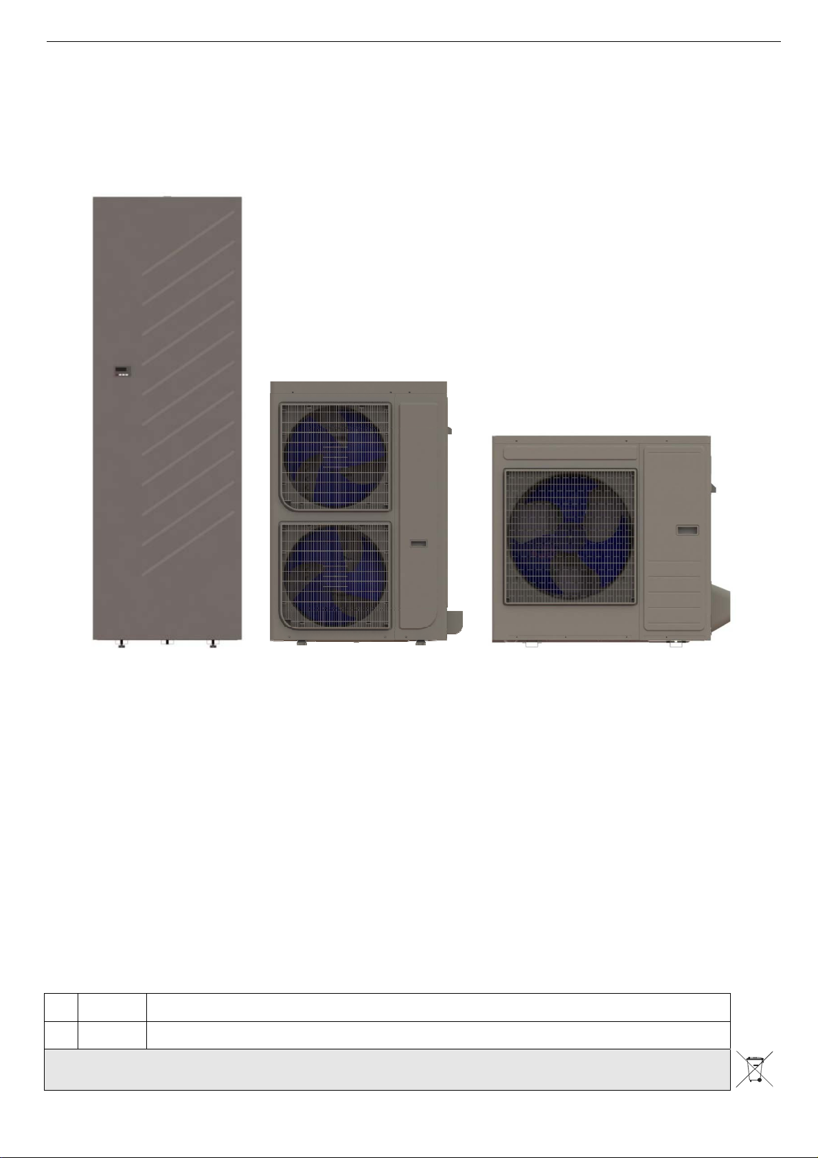
US FLOOR / FLOOR Minichiller inverter Duo
FLOOR/FLOOR-S
Internal Unit
US 06-09-12-16 External Unit
00 10-2015
Rev Date Notes
Possible wasted electrical or electronic devices/products should not be located together with normal domestic waste, but disposed according to the
current WEEE law in compliance with the European Directive 2012/19/UE. Please inform yourself at your local Administration or at your reseller in case
the product will be replaced with a similar one.
2
Page 4

US FLOOR / FLOOR Minichiller inverter Duo
INDEX
1 AIM AND CONTENTS OF THIS MANUAL ............................................................................................................... 6
1.1 HOW
1.2 GRAPHIC
TO KEEP THIS MANUAL ........................................................................................................................ ........... 6
SYMBOLS .................................................................................................................................................. 6
2 SAFETY LAWS ...................................................................................................................................................... 6
3 PERMITTED USES ................................................................................................................................................. 6
4 GENERAL SAFETY GUIDELINES ............................................................................................................................. 7
4.1 HEALTH
4.2 PERSONAL
4.3 SAFETY
4.4 REFRIGERANT
AND SAFETY OF WORKERS.......................................................................................................................... 7
PROTECTION EQUIPMENTS .................................................................................................................... 7
SYMBOLS ..................................................................................................................................................... 7
SAFETY DATA SHEET.......................................................................................................................... 8
5 GENERAL CHARACTERISTICS ................................................................................................................................ 9
5.1 MODELLI
5.2 MODEL
5.3 MODELS
DISPONIBILI .............................................................................................................................................. 9
FLOOR ......................................................................................................................................................... 9
FLOOR-S ..................................................................................................................................................... 9
6 TECHNICAL CHARACTERISTICS ............................................................................................................................. 9
6.1 FRAME ...................................................................................................................................................................... 9
6.2 REFRIGERANT
CIRCUIT ....................................................................................................................... .................... 10
6.3 COMPRESSORS ....................................................................................................................................................... 10
6.4 AIR
SIDE EXCHANGERS ........................................................................................................................................... 10
6.5 FANS ....................................................................................................................................................................... 10
6.6 USER
6.7 ELECTRIC
6.8 CONTROL
6.9 MONITORING
6.10 HYDRAULIC
6.11 FAN
6.12 OPTIONAL
HEAT EXCHANGERS ....................................................................................................................................... 10
BOX ......................................................................................................................................................... 10
SYSTEM ........................................................................................................................ .......................... 10
AND PROTECTION DEVICES ............................................................................................................. 10
CIRCUIT ....................................................................................................................... ........................ 11
SPEED CONTROLLER ....................................................................................................................................... 11
ACCESSORIES ................................................................................................................... ..................... 11
7 INSTALLATION ................................................................................................................................................... 11
7.1 GENERALITY ........................................................................................................................................................... 11
7.2 LIFTING
AND HANDLING ........................................................................................................................................ 12
7.2.1 Indoor unit ........................................................................................................................................................ 12
7.2.2 Outdoor unit ..................................................................................................................................................... 12
7.3 POSITIONING
AND MINIMUM TECHNICAL CLEARANCES ....................................................................................... 13
7.3.1 Indoor unit ........................................................................................................................................................ 13
7.3.2 Outdoor unit ..................................................................................................................................................... 13
7.4 HYDRAULIC
CONNECTIONS ................................................................................................................... ................. 14
7.4.1 Hydraulic circuit ................................................................................................................................................ 15
7.4.2 Connections positions ....................................................................................................................................... 16
7.4.2.1 Indoor unit ........................................................................................................... ....................................... 16
7.4.2.2 Outdoor unit ............................................................................................................................................... 16
7.4.3 Drainage system connection ............................................................................................................................ 16
7.4.3.1 Indoor unit ........................................................................................................... ....................................... 16
7.4.3.2 Outdoor unit ............................................................................................................................................... 17
7.4.4 Installation of the relief valve discharge pipe .................................................................................................. 17
7.4.5 Plant circuit water charging ............................................................................................................................. 17
7.4.6 Discharging of the plant circuit ........................................................................................................................ 18
7.5 INDICATIVE
DIAGRAMS OF THE PLANT CIRCUIT ..................................................................................................... 19
7.5.1 Standard schematic diagram of the plant ........................................................................................................ 19
7.5.2 Schematic diagram of the plant with DHW recirculation ................................................................................ 20
7.5.3 Particular schematic diagram of the plant with hydraulic separator and mixing valve .................................. 20
3
Page 5

US FLOOR / FLOOR Minichiller inverter Duo
7.5.4 Schema d'esempio RDZ per applicazioni in caldo/freddo con sistemi di ricambio aria/deumidificazione ...... 21
7.5.5 Schema generico RDZ per applicazioni con SOLARE ......................................................................................... 21
7.6 REFRIGERANT
7.6.1 Refrigerant diagram for models 06 and 09 ...................................................................................................... 23
7.6.2 Refrigerant diagram for models 12 and 16 ...................................................................................................... 23
7.7 ELECTRICAL
7.7.1 Indoor unit ........................................................................................................................................................ 24
7.7.1.1 Terminal block connections ....................................................................................................................... 25
7.7.2 Outdoor unit ..................................................................................................................................................... 26
7.7.2.1 Terminal block connections ....................................................................................................................... 26
7.7.3 Wiring between indoor and outdoor units ....................................................................................................... 27
7.7.4 Removal of the front-right side panel of the outdoor unit models 12 and 16 ................................................. 28
7.7.5 Safety thermostats ........................................................................................................................................... 28
8 ARCHITETTURA DEL SISTEMA ............................................................................................................................ 29
9 LAYOUT QUADRO ELETTRICO DELL’UNITA’ INTERNA ......................................................................................... 30
10 START UP .......................................................................................................................................................... 30
11 INDICATIONS FOR THE USER .............................................................................................................................. 31
12 SHUTDOWNS FOR LONG PERIODS ..................................................................................................................... 31
CONNECTIONS ................................................................................................................... ............. 22
CONNECTIONS ................................................................................................................... ................. 23
13 MAINTENANCE AND PERIODIC CHECKS ............................................................................................................. 31
13.1 ENVIRONMENTAL
PROTECTION ............................................................................................................................ 32
14 WHEN THE UNIT GOES OUT OF SERVICE ............................................................................................................ 32
15 TECHNICAL DATA............................................................................................................................................... 33
15.1 PERFORMANCE
15.2 OUTDOOR
15.3 INDOOR
UNITS ....................................................................................................................................................... 34
DATA ............................................................................................................................................ 33
UNITS .................................................................................................................................................... 33
15.3.1 Models FLOOR/FLOOR-S ................................................................................................................................... 34
16 ELECTRIC DATA .................................................................................................................................................. 35
16.1 MAXIMUM
16.2 MAXIMUM
POWER CONSUMPTION/MAX. INPUT CURRENT OF THE INDOOR UNITS 06-09 ................................. 35
POWER CONSUMPTION / MAXIMUM INPUT CURRENT OF THE INDOOR UNITS 12-16 ...................... 35
17 PUMPS PERFORMACE CURVES .......................................................................................................................... 35
18 CIRCULATOR PUMPS CURVES ............................................................................................................................ 36
19 READING OF THE INDOOR UNIT MANOMETERS ................................................................................................. 36
20 DHW INSTANTANEOUS PREPARER .................................................................................................................... 37
21 SOLAR GROUP (MODELS FLOOR-S) .................................................................................................................... 38
21.1 CIRCULATOR
21.2 CALIBRATION
21.3 LOADING
21.4 WASHING
21.5 MAINTENANCE
21.6 FACTORY
21.7 TECHNICAL
CURVE ............................................................................................................................................... 39
OF THE WATER FLOW BY USING THE FLOW CONTROLLER .............................................................. 39
OF THE PLANT CIRCUIT ....................................................................................................................... .... 39
OF THE PLANT ....................................................................................................................................... 39
OF THE CIRCULATOR PUMP .......................................................................................................... 40
SETTINGS OF THE CIRCULATOR PUMP ................................................................................................... 40
CHARACTERISTICS ............................................................................................................... ................ 40
22 OPTIONAL DHW TECHNICAL SIDE BOILER KIT ..................................................................................................... 40
23 PERFORMANCE ................................................................................................................................................. 41
24 OPERATION LIMITS ............................................................................................................................................ 43
24.1 E
VAPORATOR WATER FLOW RATE .............................................................................................................................. .... 43
24.2 C
HILLED WATER PRODUCTION (SUMMER OPERATION) ...................................................................................................... 43
4
Page 6

US FLOOR / FLOOR Minichiller inverter Duo
24.3 HOT WATER PRODUCTION (WINTER OPERATION) ............................................................................................................. 43
24.4 A
25 CORRECTION FACTORS FOR OPERAZIONI WITH GLYCOL .................................................................................... 44
26 DIMENSIONS ..................................................................................................................................................... 45
MBIENT AIR TEMPERATURE ........................................................................................................................................ 43
26.1 INDOOR
26.2 OUTDOOR
UNITS ....................................................................................................................................................... 45
UNITS .................................................................................................................................................... 45
27 ACCESS PROCEDURE TO INTERNAL PARTS ......................................................................................................... 46
27.1 INDOOR
27.2 OUTDOOR
UNIT .......................................................................................................................... ............................... 46
UNIT ..................................................................................................................................................... 46
28 COMPONENTS OF INDOOR AND OUTDOOR UNITS ............................................................................................ 47
NDOOR UNIT MODEL: FLOOR/FLOOR-S ................................................................................................................. ..... 47
28.1 I
28.2 I
NDOOR UNIT TEMPERATURE SENSORS ........................................................................................................................... 49
28.3 OUTDOOR
UNIT ..................................................................................................................................................... 49
29 FILTER CLEANING ............................................................................................................................................... 50
30 WIRING DIAGRAMS ........................................................................................................................................... 50
30.1 INDOOR
30.2 SINGLE-PHASE
30.3 OUTDOOR
UNIT ELECTRIC PANEL LAYOUT ................................................................................................................ 50
INDOOR UNIT .......................................................................................................................... ....... 51
UNITS .................................................................................................................................................... 52
30.3.1 Mod. US 06 - 09 ................................................................................................................................................ 52
30.3.2 Mod. US 12 ....................................................................................................................................................... 53
30.3.3 Mod. US 16 ....................................................................................................................................................... 54
31 LIMITATION OF WARRANTY .............................................................................................................................. 55
5
Page 7
US FLOOR / FLOOR Minichiller inverter Duo
The US manual contains all the necessary information for the better use of the equipment under safety conditions for the operator
thus meeting the requirements listed in the 2006/42/CE Equipment Directive and following amendments.
1 AIM AND CONTENTS OF THIS MANUAL
This manual provides basic information as for the selection, installation, operation and maintenance of the US units. It is
addressed to the installer and the user of the unit: it allows operating this equipment efficiently, even if the user do not have any
previous specific knowledge of it.
This manual describes the characteristics of the equipment when it was being put on the market; therefore, it may not capture
later technological improvements introduced by the company as part of its constant endeavour to enhance the performance,
ergonomics, safety and functionality.
The company introduces also technological improvements and is not constrained to update the manuals for previous versions of
appliances that could not be compatible. So make sure to use, for the installed unit, the supplied manual.
It’s recommended that, the user must follow the instructions contained in this booklet, especially those concerning the safety and
routine maintenance.
1.1 HOW TO KEEP THIS MANUAL
The manual has to be always kept with the unit it refers to. It has to be stored in a safe place, away from the dust and moisture. It
has to be accessible to all users who shall consult it any time they are in doubt on how to operate the equipment.
The company reserves the right to modify its products and related manuals without necessarily updating previous versions of the
reference material. It declines also any responsibility for possible inaccuracies in the manual if due to printing or transcription
errors.
The customer shall store any updated copy of the manual or parts of it delivered by the manufacturer as an attachment to this
manual.
The company is available to give any detailed information about this manual and to give information regarding the use and the
maintenance of its own units.
1.2 GRAPHIC SYMBOLS
Indicates operations that can be dangerous for people and/or disrupts the correct operation of the equipment.
Indicates prohibited operations.
Indicates important information that the operator has to follow in order to guarantee the correct operation of the
equipment in complete safety. It indicates also general notes.
2 SAFETY LAWS
The US units have been designed in compliance with the following Directives and Harmonized Norms:
• 97/23/CE, 2014/35/UE, 2014/30/UE, 2011/65/UE, 2012/19/UE Community Directives
• UNI EN 378-1, 378-2, UNI EN 12735-1 Norms
• CEI EN 60335-2-40 Norm
• CEI EN 55014-1, CEI EN 55014-2, CEI EN 61000-3-2, CEI EN 61000-3-3, CEI EN 62233 Norms
3 PERMITTED USES
• The company excludes any contractual and extra contractual liabilities for damages caused to persons, animals or objects, by
incorrect installation, setting and maintenance, improper use of the equipment, and the partial or superficial reading of the
information contained in this manual.
• These units have been designed only for heating and/or cooling water. Any other use not expressly authorized by the
manufacturer is considered improper and therefore not allowed.
• The location of the plant, the hydraulic and electrical circuits must be established by the planting designer and must take into
account both technical requirements as well as any applicable local laws and authorized specifications.
• The execution of all works must be performed by skilled and qualified personnel and competent in the existing rules in the
country in which the appliance will be installed.
6
Page 8
US FLOOR / FLOOR Minichiller inverter Duo
4 GENERAL SAFETY GUIDELINES
Before beginning to operate on US units every user has to be perfectly knowledgeable about the functions of the equipment and
its controls and has to have read and understood the information listed in this manual.
It’s strictly forbidden to remove and/or tamper with any safety device.
Children or unassisted disabled persons are not allowed to use the appliance.
Do not touch the appliance when barefoot or parts of the body are wet or damp.
Do not clean the unit when the power supply is ‘ON’.
Do not pull, remove or twist the electrical cables coming out from the unit, even if it is disconnected from the main
power supply.
Do not step with your feet on the appliance, sit down and/or place any type of object.
Do not spray or pour water directly on the unit.
Do not dispose of, abandon or leave within reach of children packaging materials (cardboard, staples, plastic bags,
etc.) as they may represent an environmental and life hazard.
Any routine and/or not-routine maintenance operation shall be carried out when the equipment has been shut down,
disconnected from electric and pneumatic power sources and after its pneumatic system has been discharged.
Do not put neither your hands nor insert screwdrivers, spanners or other tools into moving parts of the equipment.
The equipment supervisor and the maintenance man has to receive suitable training for the performance of their
tasks in safety.
Operators have to know how to use personal protective devices and have to know the accident-prevention guidelines
contained in national and international laws and norms.
4.1 HEALTH AND SAFETY OF WORKERS
The European Community has adopted a number of directives on workplace’s health and safety, which include 89/391/CEE,
89/686/CEE, 2009/104/CE, 86/188/CEE and 77/576/CEE directives. Every employer shall implement such provisions and ensure
that workers respect them:
Do not tamper with or replace parts of the equipment without the specific consent of the manufacturer. The
manufacturer shall have no responsibility whatsoever in case of unauthorized operations.
Using components, expendable materials or spare parts that do not correspond to those recommended by the
manufacturer and/or listed in this manual may be dangerous for the operators and/or damage the equipment
The operator’s workplace has to be kept clean, tidy and free from objects that may prevent free movements.
Appropriate lighting of the work place shall be provided so as to allow the operator to carry out the required
operations safely. Poor or too strong lighting can cause risks.
Ensure that work places are always adequately ventilated and that aspirators are working, in good condition and in
compliance with the requirements of the laws in force.
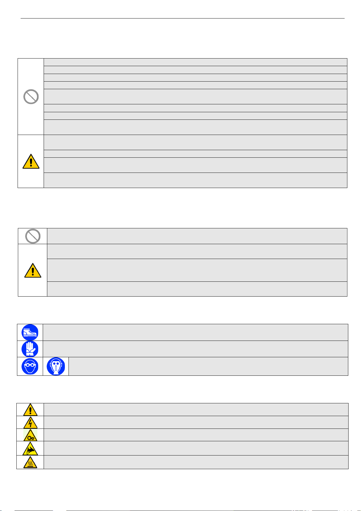
4.2 PERSONAL PROTECTION EQUIPMENTS
When operating and maintaining the US units, use the following personal protective equipment.
Protective clothing: Maintenance men and operators has to wear protective clothing that complies with the basic
safety requirements currently in force. In case of slippery floors, users have to wear safety shoes with non-slip soles.
Gloves: During maintenance or cleaning operation protection gloves have to be used
Mask and goggles: Respiratory protection (mask) and eye protection (goggles) should be used during
cleaning and maintenance operations.
4.3 SAFETY SYMBOLS
The outdoor unit features the following safety signs, which has to be complied with:
General hazard
Electric shock hazard
Presence of moving organs
Presence of surfaces that may cause injures
Presence of hot surfaces which can cause burns
7
Page 9

US FLOOR / FLOOR Minichiller inverter Duo
4.4 REFRIGERANT SAFETY DATA SHEET
Name: R410A (50% Difluoromethane (R32); 50% Pentafluoroethane (R125).
RISKS IN DICATIONS
Major risks: Asphyxia
Specific risks: The rapid evaporation can cause freezing.
FIRST AID
General informations: Never give anything by mouth to an unconscious person.
Inhalation: Outdoors opens transport.
Use oxygen or artificial respiration if necessary.
Do not give adrenaline or similar drugs
Eyes contact: Rinse carefully with water for at least 15 minutes and consult a doctor.
Contact with skin: Wash immediately with plenty of water.
Take off immediately the contaminated clothes.
FIRE PREVENTION
Extinguishing Media: Whatever.
Specifc risks: Increase in pressure.
Specifics methods: Use water spray to cool containers
MISURE IN CASO DI FUORIUSCITA ACCIDENTALE
Personal precautions: Evacuate personnel to safe areas.
Provide adequate ventilation.
Use personal protective equipment.
Environmental precautions: Evaporate.
Cleaning method: Evaporate.
MANIPULATION AND STORAGE
Manipulation
Action/technical precautions: Provide sufficient air exchange and/or exhaust in work rooms.
Recommendations for safe use: Do not breathe vapors or spray mist.
Storage: Close tightly and store in a cool, dry and well ventilated place.
Store in original container. Incompatible products: explosive, flammable materials, Organic peroxide
EXPOSURE CONTROL / PERSONAL PROTECTION
Control parameters: AEL (8-h e 12-h TWA) = 1000 ml/m³ for each of the two components.
Respiratory protection: For rescue and maintenance operation in storage tanks use self-contained respirator apparatus.
The vapors are heavier than air and can cause suffocation by reducing oxygen available for breathing.
Eyes protection: Safety glasses.
Protection of hands: Rubber gloves.
Hygiene measures: Do not smoke.
PHYSICAL AND CHEMICAL PROPERTIES
Colour: Colourless.
Odor: Light.
Boiling point: -52.8°C at atmospheric pressure.
Lighting point: do not ignite.
Density: 1.08 kg/l at 25°C.
Solubility in water: Negligible.
STABILITY AND REACTIVITY
Stability: No reactivity when used with the appropriate instructions.
Materials to avoid: Highly oxidizing materials. Incompatible with magnesium, zinc, sodium, potassium and aluminum.
The incompatibility is more serious if the metal is present in powder form or if the surfaces were, recently, unprotected.
Decomposition products These products are halogenated compounds, hydrogen fluoride, carbon oxides (CO, CO2), carbonyl halides.
Risks:
TOXICOLOGICAL INFORMATION
Acute toxicity: (R32) LC50/ inhalation /4 hours/on rat >760 ml/l
(R125) LC50/ inhalation /4 hours/on rat >3480 mg/l
Local effects: Concentrations substantially above the TLV may cause narcotic effects.
Inhalation of decomposed products of high concentrations may cause respiratory failure (pulmonary edema).
Long term toxicity: Did not show carcinogenic, teratogenic or mutagenic effects in animal experiments.
ECOLOGICAL INFORMATION
Global warming potential 1730
GWP (R11=1):
Potential depletion 0
Ozone ODP (R11=1):
Disposal considerations: Usable with reconditioning.
8
Page 10

US FLOOR / FLOOR Minichiller inverter Duo
5 GENERAL CHARACTERISTICS
5.1 MODELLI DISPONIBILI
• model FLOOR, 1-phase floor standing version, with technical water puffer tank in 190 L for DHW and technical water puffer
tank in 40 L for plant side
• model FLOOR-S, 1-phase floor standing unit, with technical water puffer tank in 190 L for DHW equipped with solar coil and
technical water puffer tank in 40 L for plant side.
5.2 MODEL FLOOR
As standard:
1) Puffer for technical water of 190 liters for DHW (domestic hot water) and plant technical puffer of 40 liters, with
polyurethane coating of 50 mm thick.
2) Circulator for the heat pump and the rapid preparer of high efficiency according to ErP directive up to values of EEI≤0.21.
3) Pump circulator and rapid preparer of high efficiency according to ErP up to the values EEI≤0,21.
4) Exchangers of the heat pump and of the DHW rapid producer in stainless steel AISI 304.
5) Integrated Y filter.
6) Tap of water charging/discharging for both DHW technical side and plant side.
7) Automatic air vent valves mounted on the plant side and on the DHW technic side.
8) Double manometer 6 bar to measure the water flow/load losses
9) Double expansion vessels of 8 liters, one on the plant circuit side and the other on DHW technic side
10) 3 bar pressure relief valve to be connected with to a collecting system
11) Flow switch for heat exchanger protection
12) Flowmeter for managing the rapid production of DHW
13) Single or three phase electric power supply
14) Electric heater controller logic for plant side in integration and/or substitution
15) Controller logic for boiler or similar source for both plant and DHW technical sides in integration and/or substitution of
the heat pump (digital contact)
16) Integrated climatic system for plant
17) Controller logic for plant remote sensor
18) Integrated controller logic for double set-point of plant side
19) Integrated controller logic for intelligent energy resources
20) Integrable with HNSBox System
Accessories:
1) Mixer’s controller logic for plant side in both heating and cooling operations. controller logic for solar integration.
Controller logic for relaunching circulator (secondary) plant side (optional kit, installed in the factory mod. GI2)
5.3 MODELS FLOOR-S
In addition to the above indicated characteristics:
1)
GI2 module for solar integration management logic. Management logic of the relaunching circulator (secondary) plantside. Mixing management logic for plant-side for both heating and cooling..
2) Integration and management of solar DHW technical-side equipped with modulating High efficiency circulator according
to ERP Directive with EEi ≤0.21.
3) Flow regulator 2÷12 l/min
4) Compact safety group with safety valve and pressure gauge.
5) Integrated ball valve with thermometer and check valve.
6) Temperature sensors DHW storage technical-side and solar collectors.
7) Expansion vessel not included to be installed externally.
6 TECHNICAL CHARACTERISTICS
The reversible heat pumps US series are designed for applications in residential and commercial areas, these units are extremely
versatile and can operate in heat pump mode with the ability of producing hot water at a temperature of 63°C using the electric
heaters for environmental heating and sanitary applications.
The new US system, which is the result of the evolution of the previous model, is the ideal solution for the total home climate
control (with the accessories Evo Touch (unscheduled) and HNS Box). For new or already existing house if equipped with a radiant
floor or fan coil as heating system, with feeding from electric power network and a renewable energy sources.
The INVERTER compressor with brushless DC motor technology, matched with electronic expansion valve, pump and variable
speed blower always with brushless motor, as well as the integrated circulators, optimize the power consumption and the
operation efficiency of the refrigerating components and of the entire system.
6.1 FRAME
All US units are made up of hot-galvanized thick sheet metal, painted with polyurethane powder enamels at 180°C to ensure the
best resistance against atmospheric agents. The frame is self-supporting with removable panels. All screws and rivets for outdoor
installations are in galvanized stainless steel. The indoor units also have a self-supporting structure made of galvanized steel with
removable painted panels.
9
Page 11

US FLOOR / FLOOR Minichiller inverter Duo
6.2 REFRIGERANT CIRCUIT
The refrigerant circuit has been manufactured by means of international primary brands components and according to the UNI EN
13134 rule concerning welding procedures. The refrigerant gas used in these units is R410A. The refrigerant circuit includes: Safety
device on the gas side, 4 way reverse cycle valve, electronic expansion valve, liquid separator (models 09, 12 and 16), oil separator
(models 12 and 16), liquid receiver, valves for maintenance and control, pressure safety device according to PED regulation (high
pressure switch), pressure transducers to accurately adjust the evaporating and condensing pressures, filters for throttling valve to
avoid its clogging, SAE valves for liquid and gas line.
6.3 COMPRESSORS
The used DC inverter compressors are a rotary hermetic type (for the models 06) and twin rotary (for the models 09, 12 and 16),
and scroll type (for the model 16) designed to be used with R410 refrigerant. The compressors are all supplied with crankcase
heater and thermal overload protection. They are mounted on a rubber material acting as shock absorbers.
The compressors are mounted in a separate chamber in order to be separated from the air flow for reducing noises. The crankcase
heater operates when the compressor remains off for duration no less than 30 minutes and when the discharge temperature is
under 20°C (with hysteresis of 2.0°C). When the compressor restarts, the crankcase heater will stop operation. We recommend to
turn on the unit and to put it in standby mode at least 6 hours before the first startup. The checking is possible through the front
panel of the unit that allows the maintenance of the compressors even if the unit is working.
6.4 AIR SIDE EXCHANGERS
The air side exchangers are made up of copper pipes and aluminum fins. The diameter of the copper pipes is 7mm for the model
06 and 09 and 5/16” for the other models 12 and 16, the thickness of the aluminum fins is 0,1mm. The pipes are mechanically
expanded into the aluminum fins to improve the heat exchange factor. The geometry of these condensers guarantee a low air side
pressure drop and, then, the use of low rotation speed (and low noise emission) fan motors.
6.5 FANS
The fans are axial type with aluminum aerofoil blades. They are statically and dynamically balanced and supplied complete of the
safety fan guard according to the CE EN 60335-2-80 rule (safety for electrical apparatus of domestic and similar use). They are
mounted on the unit frame by interposition of rubber vibration dampers. The electric motors are all brushless DC type with 8
poles (about 200/1000 rpm). The motors are directly driven with an integrated thermal overload protection. The protection class
of the motors is IP X4.
6.6 USER HEAT EXCHANGERS
The user heat exchangers are made up of AISI 304 stainless steel braze-welded plate’s type. The user heat exchangers are factory
insulated with flexible close cell material. Each evaporator is provided with a temperature sensor working as antifreeze protection
that activates the circulator, even in the case when the unit is turned off when the condition parameters set in the controller have
been occurred.
6.7 ELECTRIC BOX
The electric box is manufactured according to according current European Union laws. The accessibility to the electric board is
possible after removing the side and top panels of the outdoor unit by using an appropriate tool, and by removing the ABS plastic
cover for the indoor units. The protection degree is IP24. The outdoor unit terminal board is supplied with voltage free contacts
for general alarm. The indoor unit terminal board is supplied with contacts for the sanitary water temperature sensor, auxiliary
heater and the handling of the outer 3-way valve.
6.8 CONTROL SYSTEM
All US units are equipped with a microprocessor adopting an overheating control logic program through the electronic
thermostatic valve managed by the pressure transducers signals and temperature sensor. The microprocessor can manage also
the following functions: water temperature regulation, antifreeze protection, compressor’s time setting, compressor automatic
starting sequence, alarm reset, alarm management and operating LED. The control system together with the INVERTER technology
and the on board sensors continuously monitor and adapt the performance of the inverter compressor, and of the fan (2 fans as
for the US 12 and US 16 models).
The INVERTER system allows to reduce the plant’s water content to the minimum, that is from the usual value of cooling 12-16
l/kW to 18 liters for the model US 06, to 25 liters for the model US 09, to 35 liters for the model US 12 and to 45 liters for the
model US 16 in ABSOLUTE, as for the US units can also be installed in plants without water tank with advantages in terms of the
reduced dimensions of the unit, the installation space, the heat loss, the installation costs and the plant maintenance.
6.9 MONITORING AND PROTECTION DEVICES
All internal units are standard supplied with the following monitoring and protection devices: return water temperature sensor
installed at the return water pipe line from the plant, operating and antifreeze sensor installed at the outlet pipe of the water to
the plant and on water side a water flow switch is installed to protect the evaporator. All internal units are supplied with high
pressure transducer, low pressure transducer, compressor’s inlet and outlet temperature sensors, compressors thermal protection
device, fans thermal protection device, high pressure flow switch HP.
10
Page 12
US FLOOR / FLOOR Minichiller inverter Duo
CAUTION: The INVERTER control system is able to manage in the plant the minimum water contents up to a value
of 18 liters for the 06 model, of 25 liters for the 09 model, of 35 liters for the 12 model, and of 45 liters for the 16
model. This value makes reference to the liters absolute value and not to any kW of installed power.
6.10 HYDRAULIC CIRCUIT
The US outdoor units are supplied with an integrated hydraulic circuit including a high efficiency (EEI≤0,23) modulating BRUSHLESS
circulator, suitable also for chilled water utilization and is directly managed by the controller on board the unit, Y filter with a mesh
of 1000 µm, plate heat exchanger, flow switch for protection, 3-way valve for commutation between plant side and DHW technical
side, expansion vessel of 8 liters plant circuit side (standard in FLOOR/FLOOR-S models), expansion vessel of 8 liters plant side, the
automatic air release valve and relief valve (3 bar) to be connected to the collecting system.
6.11 FAN SPEED CONTROLLER
This type of control is managed by the microprocessor and is necessary for optimizing the pressure of evaporation/condensation
during summer/winter operation in order to allow proper running of the unit.
6.12 OPTIONAL ACCESSORIES
NO FACTORY FITTED ACCESSORIES (OPTIONAL)
Rubber shock absorbers to be inserted at the basement of the outdoor unit to dampen possible vibrations.
Antifreeze kit. It uses a self-heating cable wrapped at the basement of the outdoor unit near the condensing coil.
IMPORTANT
ONLY THE NO FACTORY-FITTED OPTIONA ACCESSORIES CAN BE REQUIRED AFTER THE ORDER OF THE UNIT, WHILE THE
FACTORY-FITTED OPTIONAL ACCESSORIES CANNOT BE REQUIRED AFTER ORDERING OF THE UNIT.
7 INSTALLATION
WARNING: All the operation described below MUST BE DONE BY TRAINED PEOPLE ONLY. Before any operation on the
unit, be sure that the electric supply is disconnected.
7.1 GENERALITY
When installing or servicing the unit, it is necessary to strictly follow the rules listed in this manual, to conform to all the
specifications of the labels on the unit, and to take any possible precautions. Not observing the rules reported on this manual can
create dangerous situations.
After receiving the unit, immediately check its integrity. The unit left the factory in perfect condition; any eventual
damage has to be questioned to the carrier and recorded on the Delivery Note before signing it.
The company has to be informed, within 8 days, of the extent of the damage. The Customer should prepare a written statement of
any severe damage.
WARNING: The moto-condensing units are designed for outdoors installation. The installation place should be
enough away. From far risks. Therefore all the necessary measures should be adopted in order to prevent the risk of
fire at the installation place. In any case the outside temperature must not exceed 46°C. Beyond this value, the unit is
no longer covered by the actual regulations in the field of safety of pressure equipment.
WARNING: If they should be installed in an areas of the building subject to low temperatures (attics, basements,
etc.), refer please to the precautions listed in Chapters 12 and 25).
WARNING: The unit must be installed so as to allow for the repair and maintenance operations. The warranty does
not cover costs due to platforms or other lifting systems needed for eventual interventions.
All checks and maintenance operations must be carried out only by qualified personnel.
Before any operation on the unit, make sure that the electric supply is disconnected.
WARNING: Inside the unit, there are some moving components. Be very careful when operating in their surroundings
even if the electric power supply is disconnected.
The top part and discharge pipes of the compressor operating at high temperatures. Be sure to let the unit to become
cool before beginning any maintenance work.
Be especially careful when going to operate in the surrounding of the coils.
The aluminum fins are very sharp and can cause serious injury.
After the maintenance operations, close the panels by fixing them with screws.
11
Page 13
US FLOOR / FLOOR Minichiller inverter Duo
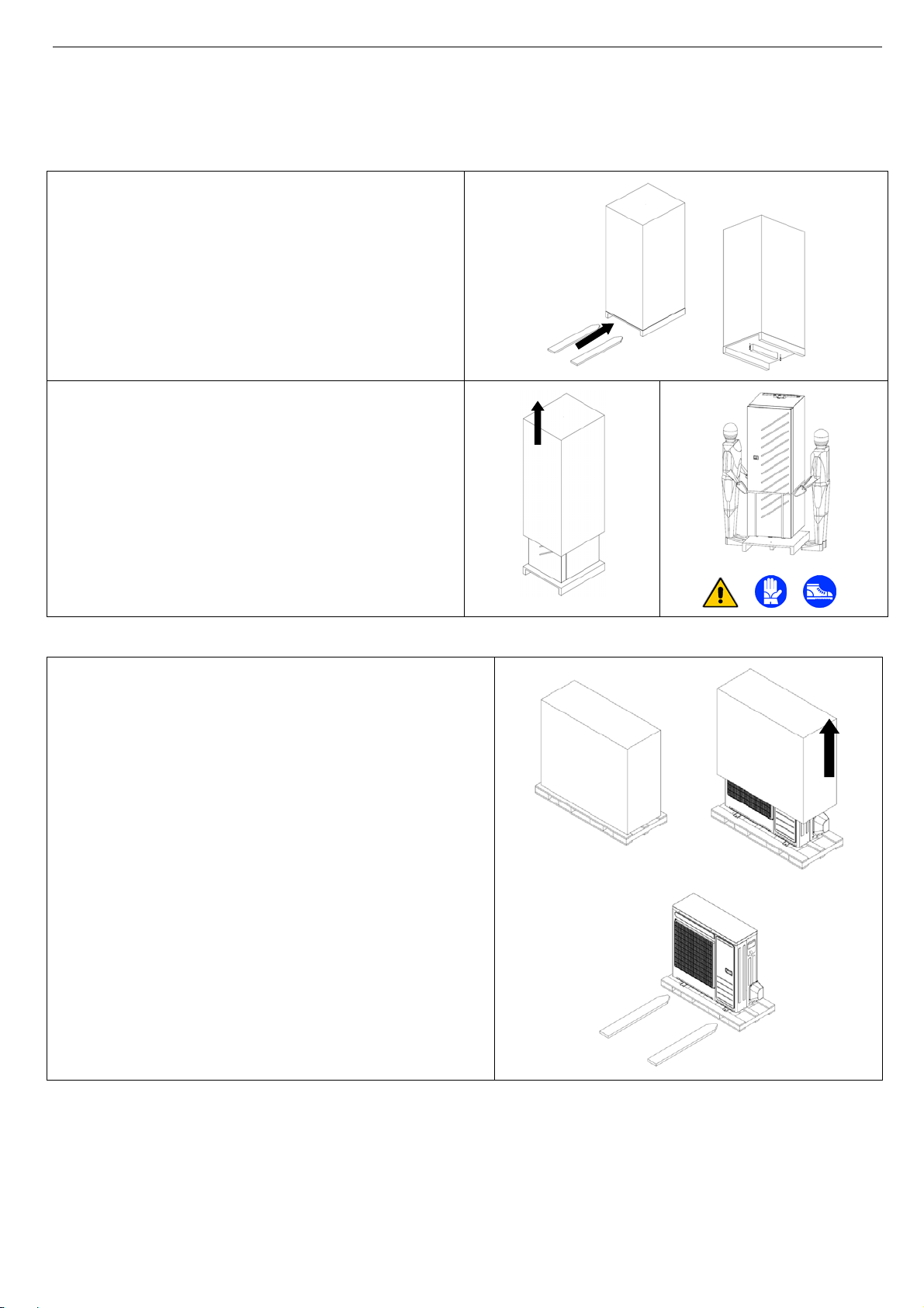
7.2 LIFTING AND HANDLING
The handling must be performed by qualified personnel, properly equipped with appropriate equipment regarding the weight and
the encumbrance of the unit, in compliance with safety regulations of accident preventing.
7.2.1 Indoor unit
• The apparatus is supplied on wooden pallets protected by
carton packing box.
• Do not place anything on the top of the carton box.
• Insert the forks from the indicated side.
• During the unloading of the unit, utmost care must be
taken to avoid abrupt or violent maneuvers in order to
protect the internal electronic components.
• During handling keep the unit vertically.
• Before you remove the packaging, loosen the screws
securing the unit to the pallet.
It is recommended to unpack the unit only with equipment
positioned near the installation place, otherwise take special
care not to damage the unit when handling it.
Removal of the packing box:
• Cut the strap fasteners.
• Lift the carton box upward.
• Remove the corner pieces of polystyrene foam.
• Remove the unit from the pallet using a suitable belt straps
(at least two persons equipped with suitable protective
equipment for the hands and feet)
7.2.2 Outdoor unit
It is recommended to unpack the unit only with equipment
positioned near the installation place, otherwise take special care
not to damage the unit when handling it.
Removal of the packing box:
• Cut the strap fasteners.
• Remove the apparatus by lifting the packing upward.
• Remove the corner pieces of polystyrene foam.
• Remove the unit from the pallet by unscrewing the screws that
hold the feet to the pallet itself.
When unloading and installing the unit, it is highly recommended to
avoid any sudden move in order to protect the inner components.
Units can be lifted by means of a forklift or, in alternative, of belts,
being sure not to damage the lateral panels and the cover. It is
important to keep the unit horizontal during these operations.
12
Page 14
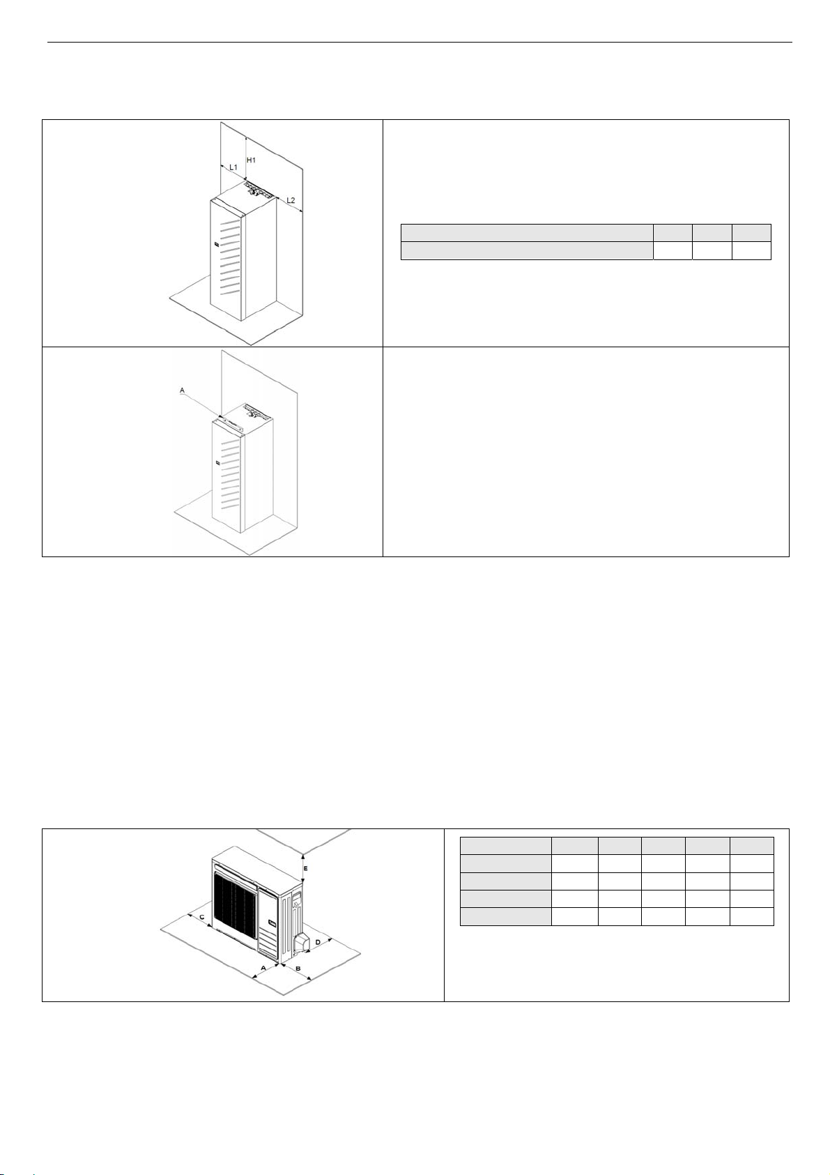
7.3 POSITIONING AND MINIMUM TECHNICAL CLEARANCES
7.3.1 Indoor unit
The installation must allow authorized personnel to operate in the
event of maintenance, in an easy manner respecting both the safety
distances between the units and other apparatus that the technical
spaces (expressed in mm) indicated in the table:
FLOOR/FLOOR-S 06-09/12-16 300 300 300
(*) Recommended distances for lateral inspection in case of
concealed installation. In case concealed installation, the inspection
side is not required and you can keep up to 5 mm on each side.
• Make sure that the equipment is installed and protected from
the weather elements in a clean and dry location.
• Place the unit on the wall.
• The feet should be in horizontal level.
(A) Level
US FLOOR / FLOOR Minichiller inverter Duo
MOD. L1* L2* H1
7.3.2 Outdoor unit
All the outdoor units of US series are designed for outdoor installation: any cover over the unit and location near trees (even if
they partially cover the unit) is avoided in order to allow the air recirculation. It is advisable to create a proper basement, with a
size similar to unit foot-print. Unit vibration level is very low: it is advisable however, to fit a rigid rubber band between basement
and unit base-frame. It is also possible to install anti-vibration supports (springs or rubbers) to keep vibrations at a very low level.
Absolute care has to be taken to ensure adequate air volume to the condenser. Re-circulation of discharge air has to be avoided;
failure to observe this point will result in poor performance or activation of safety controls. For these reasons it is necessary to
observe the following clearances (expressed in mm):
MOD. A B* C D E**
06 1500 500 400 400 500
09 1500 500 400 400 500
12 1500 500 400 400 500
16 1500 500 400 400 500
* Minimum clearances recommended for installation
and maintenance.
** Minimum clearances recommended for assistance
and maintenance.
13
Page 15
US FLOOR / FLOOR Minichiller inverter Duo
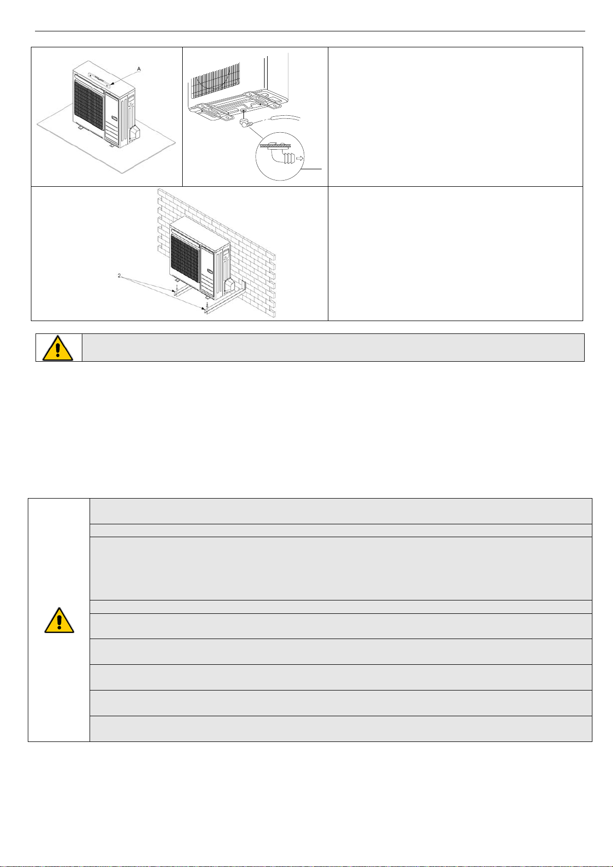
Positioning on the floor
Provide lifting from the floor of the unit:
• 20 mm without conveying the condensate drain
• 90 ÷ 100 mm to allow the conveying of the
condensate drain
In case of installation in areas subjected to extreme cold
or heavy snow, where there is the possibility of freezing,
it’s recommended to provide suitable frost protection
systems.
1
(A) Level
(1) condensate drain pipe
Suspended positioning
• In the case of suspended installation, adequate
brackets must be used to support the weight of
the unit and also depending also on the type of
the wall to which should be fixed.
• Make sure that the section of the wall doesn’t
overlap to bearing elements of construction,
pipelines or power lines.
(2) brackets for positioning (not supplied with the unit)
Both units must be positioned on a leveled surface, the holders used for installation must be able to support its
weight.
7.4 HYDRAULIC CONNECTIONS
The hydraulic connections have to be installed in accordance with national and/or local regulations; pipes can be made up of steel,
galvanized steel or PVC. Pipes have to be designed depending on the nominal water flow and on the hydraulic pressure drops of
the system. All pipes have to be insulated with closed-cell material of adequate thickness. It is recommended to connect the
indoor unit to the piping using flexible joints. The hydraulic circuit should include the following components:
• Hole thermometers to monitor the circuit’s temperature.
• Manual shut-off valves to separate the chiller from the hydraulic circuit.
• Charging group and discharge valve.
• Anti-vibration joints and supports for the piping where necessary.
WARNING: make sure that the size of the pipes shall not exceed the maximum head loss on the plant side given in
the table in the Paragraph 15.3 (see the available pressure head data).
WARNING: connect the pipes to their attacks always by the way of key against key method.
WARNING: The plant side expansion vessel included in the models FLOOR/FLOOR-S has a limited capacity of 8
liters. The installer should verify that if the expansion vessel is adequate to the real capacity of the plant circuit,
otherwise should be provide an additional expansion vessel.
For the installation position of the expansion vessel (indicated as additional expansion vessel), please refer to
Paragraph 7.5.
WARNING: check that the weight of the pipes does not grave about the structure of the machine.
WARNING: unit water return pipe should be in correspondence with the connection labelled: ”TECHNIC WATER
RETURN”, otherwise the evaporator may freeze.
WARNING: If the water flow switch (factory mounted) is altered or removed, the warranty will no longer be valid.
Please refer to the wiring diagram for the water flow switch electric connections.
The metallic Y-filter with 1 mm mesh must be kept clean, so make sure that it is still clean after the installation of
the unit, and then check it periodically.
The water on the charging/topping-up pipe must be opportunely pre-filtered from any suspended particles and
impurities through the use cartridge filter (washable, wrapped wire, etc.) of at least 100 microns.
Check the water hardness with which you load and top up the plant circuit. With particularly hard water, in this
case it is necessary to utilize a water softener. For treating water for the plant, please refer to UNI 8065.
14
Page 16
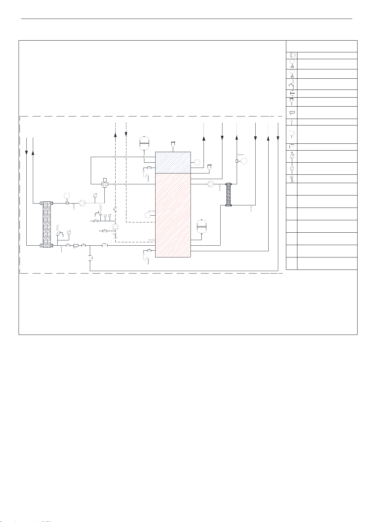
7.4.1 Hydraulic circuit
INDOO
RUNI
DRONICCIR
CUIT(model
e
p
i
p
d
i
u
q
Gas pipe
i
L
Exchanger
R410A/water
FS
2
P
1
To solar plant
Diverter valve
D
P
P
T
US FLOOR / FLOOR Minichiller inverter Duo
Key
Circulator pump
FS
Flow switch
FM
Flow meter
3 bar relief valve
8 liters expansion vessel
Air vent valve
-filter with metallic mesh of
T HY
(mod. FLOOR-S)
From solar plant
(mod. FLOOR-S)
Plant side Puffer
DHW technical
side Puffer
3
R
7
: MARP/MARPS)
To the plant
R
From the boiler (KCACS kit)
4
Water supply inlet
To the DHW-R ulity
6
FM
5
From the plant
To the boiler (OPTIONAL)
Y
1000µ
Temperature sensor
Oponal auxiliary electric
R
heater with double
protecon thermostat
Check valve
Manometer 0-6 bar
Dial thermometer
Flow regulator valve
Heat exchanger inlet
1
sensor
Heat exchanger outlet
2
exchanger
DHW technical side
3
sensor
Primary circuit inlet sensor
4
DHW-R
Secondary circuit sensor
5
DHW-R
Secondary circuit outlet
6
sensor DHW-R
Solar management sensor
7
(models MRS – FLOOR-S)
15
Page 17
US FLOOR / FLOOR Minichiller inverter Duo
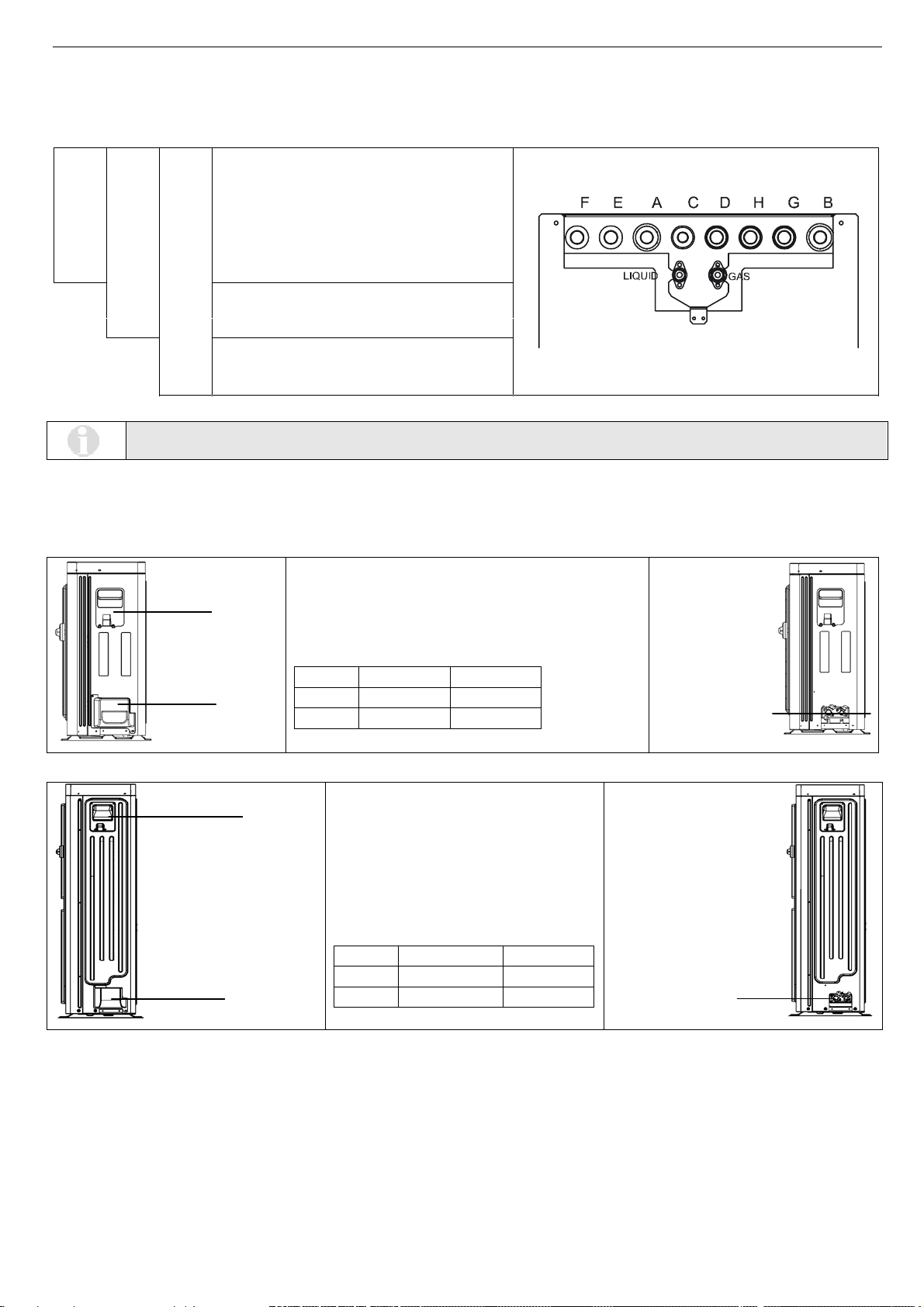
7.4.2 Connections positions
7.4.2.1 Indoor unit
A. From the plant (1”M)
B. To the plant (1”M)
C. Water supply inlet (3/4”M)
FLOOR
FLOOR-S
D. The user DHW-R (3/4”M)
I. Liquid line (see Paragraph 15.3)
L. Gas line (see Paragraph 15.3)
For DHW-R user, it means the point(s) of using of domestic hot water produced by the instantaneous preparer DHW.
The DHW-R means “rapid” production of the domestic hot water.
7.4.2.2 Outdoor unit
Units 06 and 09
Units 12 and 16
FLOOR / FLOOR-S with boiler kit
E. From the solar plant (3/4”M)
F. To the solar plant (3/4”M)
G.
From the boiler (3/4”M) (oponal)
H.
To the boiler (3/4”M) (oponal)
A. Power supply cover (to reach the terminal block)
A
B. Gas connecons cover
C. Gas connecons
Models Liquid pipe Gas pipe
B
06 1/4 SAE 1/2 SAE
09 3/8 SAE 5/8 SAE
I
L
C
A
A. To reach the power supply and signal
cables (remove the rear side cover to
reach the terminal block)
B. Gas connecons cover
C. Gas connecons
Models Liquid pipe Gas pipe
12 3/8 SAE 5/8 SAE
B
16 3/8 SAE 5/8 SAE
C
7.4.3 Drainage system connection
7.4.3.1 Indoor unit
The connecon of a condensate drainage system is not necessary for the indoor units since all pipes and cold components are
insulated with closed-cell foam of an adequate thickness.
16
Page 18
US FLOOR / FLOOR Minichiller inverter Duo
7.4.3.2 Outdoor unit
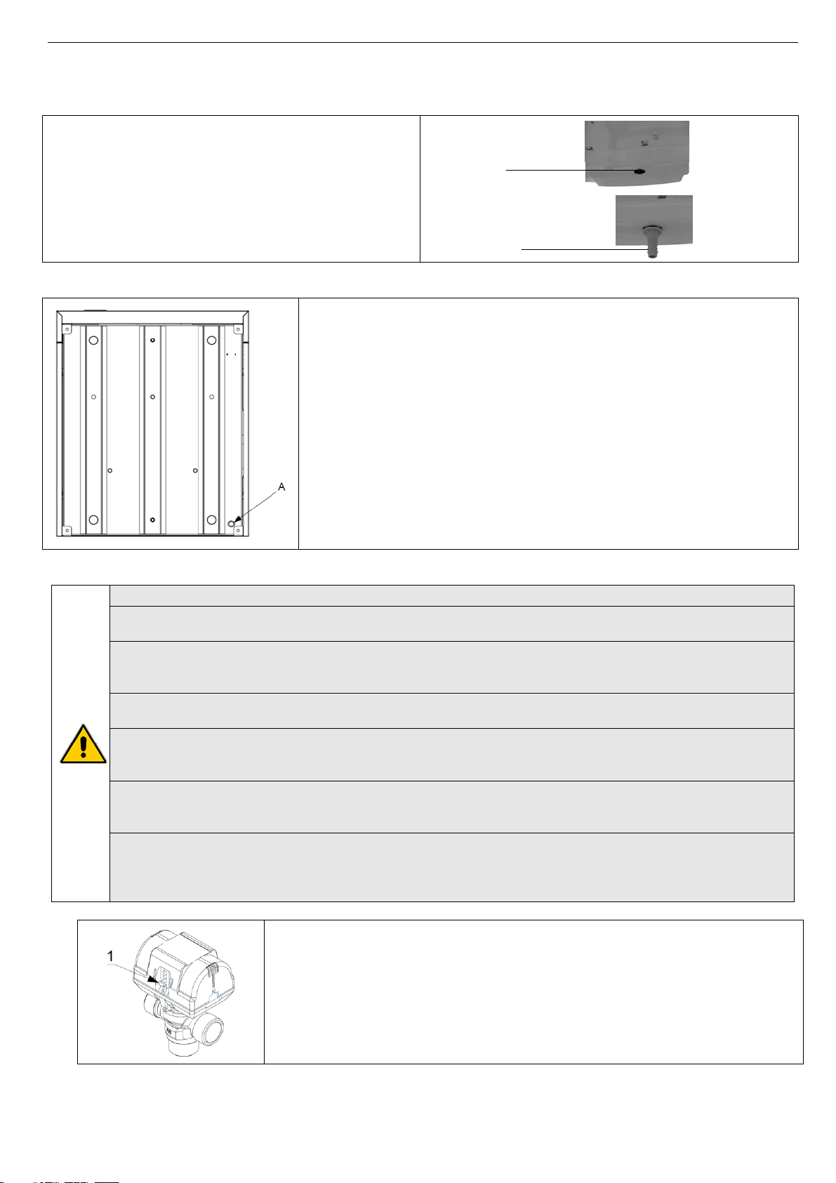
All the outdoor units have been designed in a way to use their own basement as a drain pan.
• Locate the hole at the basement of the unit between the
finned coil and fan, A.
• Connect to the hole the provided fing joint, B.
• Connect a hose to the nozzle of the supplied fing joint.
• Direct the hose into the disposal place for condensate
water.
• Keep a sufficient slope to ensure the smooth flow of
condensate water.
7.4.4 Installation of the relief valve discharge pipe
On the basis of the indoor unit there is a drain pipe in PVC, internally connected to
the unit on both safety valves outlet connecons of the plant side/DHW technical
side and of the solar integraon circuit (FLOOR-S model) in order to ensure the
proper discharge of the water when the relief valve opens in case of overpressure.
• Connect a rubber pipe to the drain pipe by means of hose pipe joint connector of
14 mm (not supplied)
• Secure it with pipe clamp.
• Direct the hose towards an appropriate locaon for unloading.
• A sufficient slope should be maintained to ensure the smooth flow.
• Do not "strangle" the pipe.
• Check for proper water drainage
A) hole for overpressure valve discharge
B
7.4.5 Plant circuit water charging
WARNING: Verify all the charging/topping-up operations.
WARNING: Before beginning the charging/topping-up operation of the plant circuit, disconnect the unit for the
electric power supply.
WARNING: The charging/topping-up of the plant circuit must always be done under controlled conditions of
pressure (max 1 bar). Make sure that you have installed on the line of charging/topping-up a pressure reducer and
a relief valve as indicated in the Paragraph 7.5.
WARNING: The water on the charging/topping-up pipe must be suitably pre-ltered from any impurities and
suspended particles. Make sure that you have installed a ca rtridge lter removable as indicated in Paragraph 7.5.
WARNING: before proceeding to the charging/topping-upof the plant circuit, place in mid-travel the 3-way valve
of the indoor unit by actuating the black lever. Restore the normal position of the black lever after nishing the
charging/topping-up operation of the plant circuit.
WARNING: Before beginning the charging /topping-up operation, unscrew the plugs of the air vent valves
(two on FLOOR/FLOOR-S models). Tighten the plugs after nishing the operation of
charging/topping-up of the plant circuit system.
WARNING: instead of using a xed installation of the line lling/topping up, as indicated in Paragraph 7.5, you can
alternatively use the discharge valves of which is already provided with the puer of the indoor unit. In this case, it
is mandatory that the inlet water should be pre-ltered with (with at least 100 microns pre lter) and the pressure
of the water entering should be controlled (max 0.8 to 1 bar).
During the charging/topping-up operaon, the black lever of the 3-way valve (located at
the top of the valve) must be posioned halfway and kept in that posion by making a
pressure toward the valve interior. In this mode all the three ways (AB-A-B) communicate
with each other and consequently the plant side with DHW technical side. To unlock the
valve, aer the end of charging period, push the lever down unl the complete release
(check if the lever returns to its lied posion).
Refer to pos. 10 Paragraph 28.1.
(1) Black lever three-way valve
17
Page 19
US FLOOR / FLOOR Minichiller inverter Duo
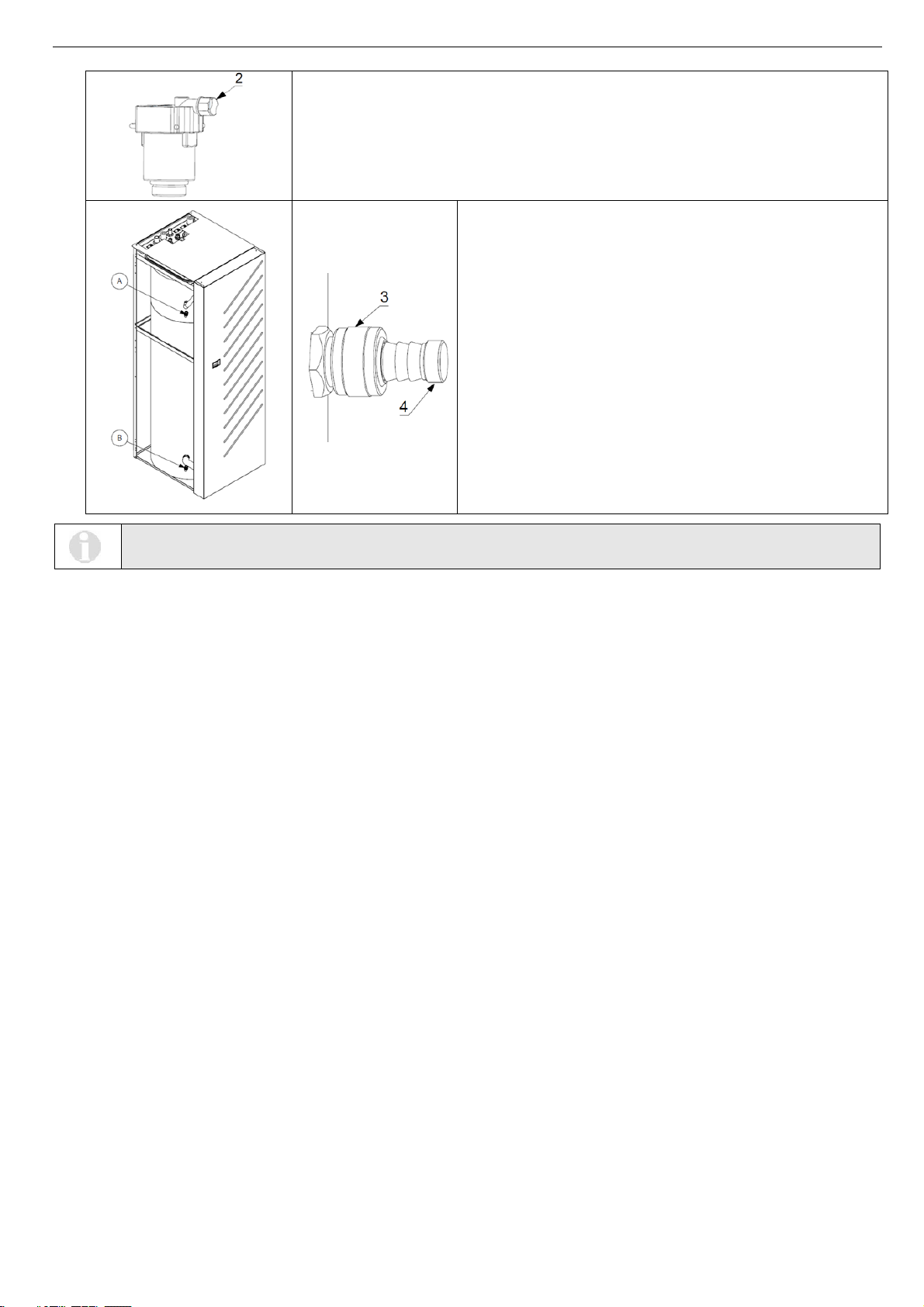
During the operations of charging/topping-up, the plugs of the air vent valves must be
partially unscrewed to allow air to flow freely out of the valves.
The models FLOOR/FLOOR-S are equipped with two air vent valves, one on the other DHW
technical side puffer and the other on the puffer of the plant side.
(2) Stopper of the air vent valve
When it’s necessary to top up the circuit of the plant or to adjust
the title of glycol (in the cases described in Chapter 25), you can
use the service valves. Unscrew the cap of the service valve and
connect to joint connector a hose pipe of 14 mm (inner diameter)
which should be connected to the water supply, then unscrew
the knurled nut to load the plant circuit. At the end of the
operation, retighten the knurled nut and screw the cap. At any
case, it‘s recommended to use an external water tap for loading
the plant circuit, this should be done by the installer.
(A) service valve of plant side puffer tank (models
FLOOR/FLOOR-S)
(B) service valve of DHW technical side puffer tank
(3) knurled nut
When the three-way valve is de-energized, it is turned to B position (towards the plant side).
Looking at the front side of the valve, the way normally open (B) is in the left side.
(4) stopper with gasket
7.4.6 Discharging of the plant circuit
If it‘s necessary to drain completely the indoor unit, connect with a pipe to the service valves (both service valves for the models
FLOOR/FLOOR-S). Then unscrew the cap of the service valve and connect to the hose pipe joint connecter a pipe of 14 mm (inner
diameter) which must be connected to the drain water, then proceed to evacuate the plant circuit by unscrewing the knurled nut.
After the end of the process, close again the knurled nut and screw the cap. Refer to the previous paragraph regarding the
position and the utilization mode of the valves.
18
Page 20
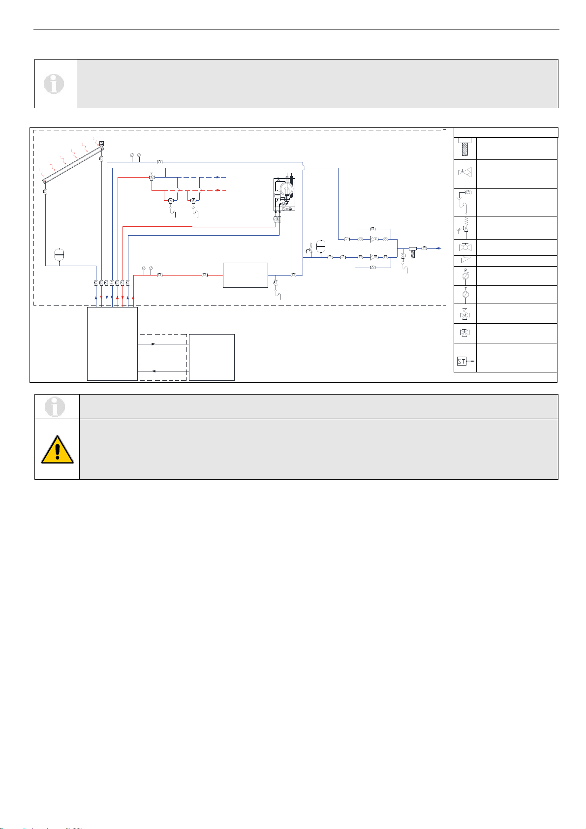
7.5 INDICATIVE DIAGRAMS OF THE PLANT CIRCUIT
WARNING: The diagrams shown in this paragraph are should be considered only for illustration purpose.
The study and the approval of the specic installation context of the plant is always required by a qualied heating
engineer.
7.5.1 Standard schematic diagram of the plant
P T
To t he plan t
To t he dome sc utili e s
US FLOOR / FLOOR Minichiller inverter Duo
Key
Filter with extractable
cartridge
Loading group with
pressure reducer
device
To t he sola r plan t
Discharging valve
3 bar relief valve
Shut-off valve
Check valve
Manometer 0-6 bar
Dial thermometer
Solar plant
expansion vessel
(not supplied)
BOILER
To DHW u lity
From the so lar pla nt
From t he boi ler (techn icla wa ter)
To th e boil er (techn ical wat er)
P T
To t he plan t
PLANT
Addional
expansion vessel
(not supplied)
Charging/topping up line
THIS RE COMM ENDED CONNECTIONS
SHOULD BE DO NE BY T HE INST ALLER
Water
supply
inlet
3-way an-scalding
thermostac valve
Domesc water
mixer
Hydronic circuit
Indoor unit
(models: FLOOR-S)
Piping connecons for
gas and liqui d shall be
done by the installer
OUTDOOR UN IT
NTC temp. sensor for
immersion (solar
collector)
All the components inside the dashed line "CONNECTIONS THAT SHOULD BE DONE BY THE INSTALLER" are
indicated but are not supplied.
WARNING: It is recommended to install a 3 bar relief valv e (not supplied) as shown in the plant diagram. It is
necessary to install one automatic air vent at the highest point of the plant circuit.
An additional expansion vessel is required (not supplied) for absorbing the volume changes in the plant circuit side.
The integrated 8 liters expansion vessel is expected in the models FLOOR/FLOOR-S. Please install an additional
expansion vessel if the integrated one is judged insucient.
19
Page 21
US FLOOR / FLOOR Minichiller inverter Duo
T
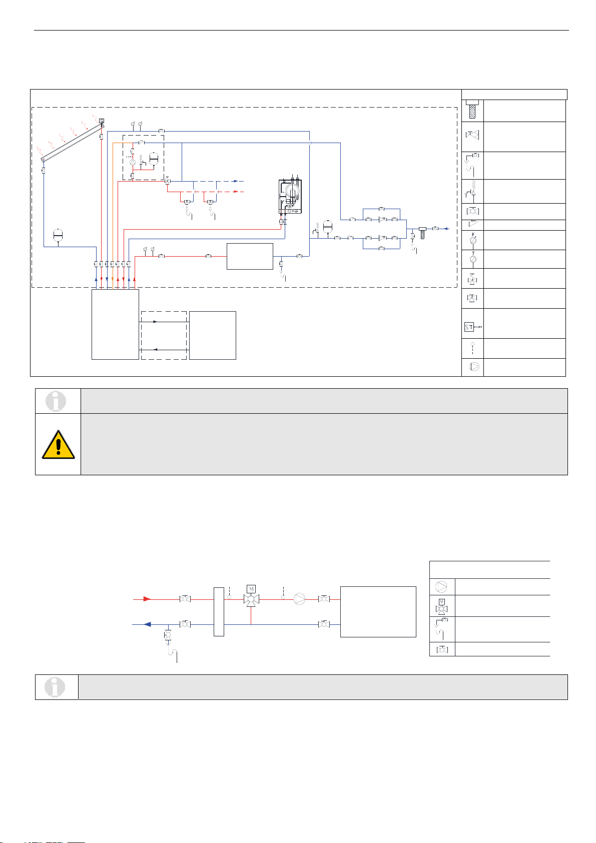
7.5.2 Schematic diagram of the plant with DHW recirculation
Please note that the opon of the DHW recirculaon is available when the addional plant management module (oponal GI2
oponal) is present.
Key
Filter with extractable
cartridge
Loading group with
pressure reducer
device
Discharging valve
3 bar relief valve
Shut-off valve
Check valve
Manometer 0-6 bar
Dial thermometer
3-way an-scalding
thermostac valve
Domesc water
mixer
NTC temp. sensor for
immersion (solar
collector)
DHW recirculaon
temp. sensor
Circulator pump
To the so lar plant
Solar plant
expansion vessel
(not supplied)
(model: FLOOR-S)
From the solar plant
Hydronic circuit
Indoor unit
P T
DHW circulaon
y
t
i
l
i
t
u
R
W
H
D
o
T
P T
Piping connecon for
gas and liqui d shall be
done by the installers
From the plant
Expansion
vessel
To the boiler (technical water)
To the plant
OUTDOOR UNIT
To the d omesc utili es
Boiler
PLANT
Addional
expansio n vessel
(not suppl ied)
Charging/topping up pipe
THIS RECOMM ENDED CONNE CTIONS
SHOULD BE DONE BY THE INSTALLER
Water
supply
inlet
All the components inside the dashed line "CONNECTIONS THAT SHOULD BE DONE BY THE INSTALLER" are
indicated but are not supplied.
WARNING: It is recommended to install a 3 bar relief valve (not supplied) as shown in the plant diagram.
It is necessary to install one automatic air vent at the highest point of the plant circuit.
An additional expansion vessel is required (not supplied) for absorbing the volume changes in the plant circuit side.
The integrated 8 liters expansion vessel is expected in the models FLOOR/FLOOR-S. Please install an additional
expansion vessel if the integrated one is judged insucient.
7.5.3 Particular schematic diagram of the plant with hydraulic separator and mixing valve
Plant rem ote sensor Mixing water sen sor
AB
To the plant circuit
echnic water return
hydraulic separator
The indicated components are not supplied and their connection should be done by the installer. The remote plant
circuit sensor is always managed. The management of the mixing sensor is possible only with optional module GI2.
A
B
Plant
KEY
Cir colator pu mp
3-way valve mo torized
in two -posion
Discharge valve
Shu t-off valve
20
Page 22
US FLOOR / FLOOR Minichiller inverter Duo
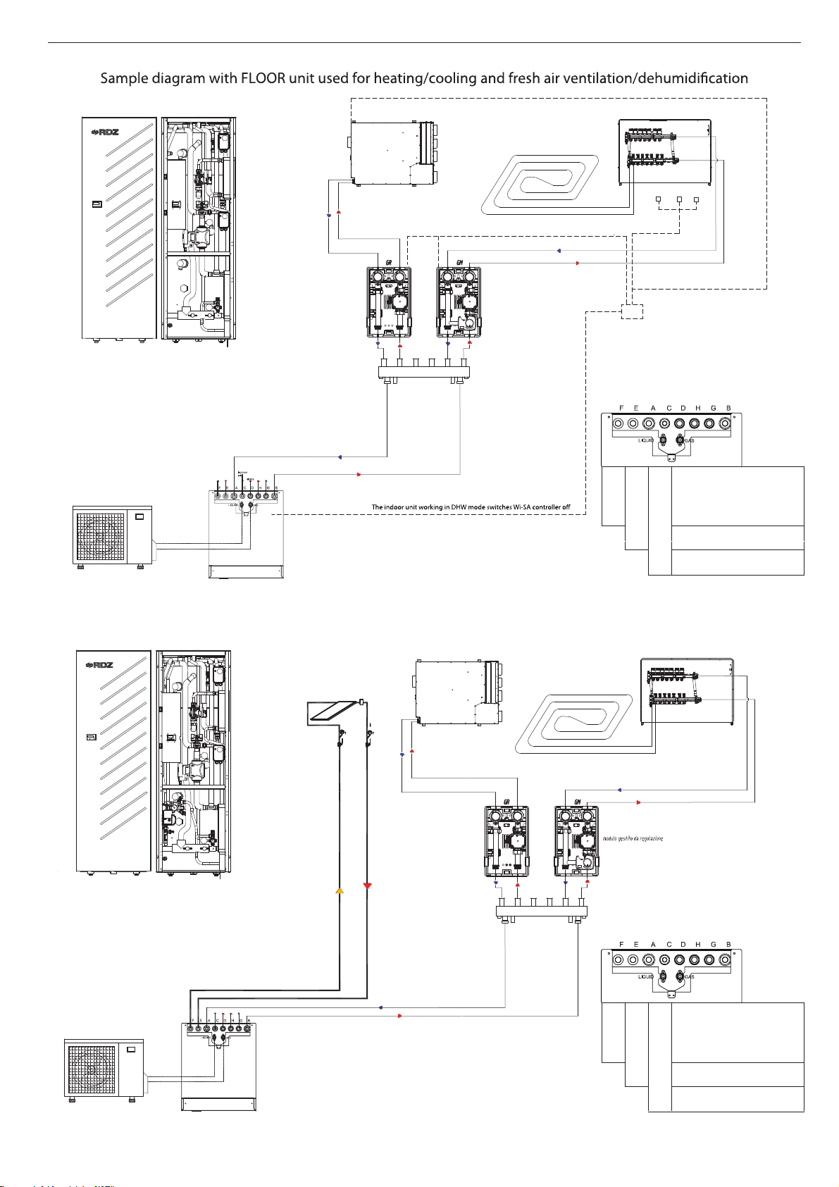
7.5.4
FLOOR Door FLOOR Contents
Outdoor Unit
Safety drainage
FLOOR
High side
UC 300 MHE
controls/signals
FLOOR
room sensor
bus
bus
Wi-SA Regulation
I
FLOOR-S
FLOOR / FLOOR-S with boiler kit
CONTROL
L
A. From the plant (1”M)
B. To the plant (1”M)
C. Water supply inlet (3/4”M)
D. The user DHW-R (3/4”M)
I. Liquid line (see Paragraph 15.3)
L. Gas line (see Paragraph 15.3)
E. From the solar plant (3/4”M)
F. To the solar plant (3/4”M)
G. From the boiler (3/4”M) (oponal)
H. To the boiler (3/4”M) (oponal)
7.5.5
Sample diagram with FLOOR-S unit with Solar Application
FLOOR-S Door FLOOR-S Contents
Outdoor Unit
DHW Solar
Safety drainage
FLOOR
High side
Solar Panel
UC 300 MHE
Manifold
with
separator
CONTROL
I
FLOOR
FLOOR-S
L
A. From the plant (1”M)
B. To the plant (1”M)
C. Water supply inlet (3/4”M)
D. The user DHW-R (3/4”M)
I. Liquid line (see Paragraph 15.3)
L. Gas line (see Paragraph 15.3)
E. From the solar plant (3/4”M)
F. To the solar plant (3/4”M)
G. From the boiler (3/4”M) (oponal)
FLOOR / FLOOR-S with boiler kit
H. To the boiler (3/4”M) (oponal)
21
Page 23
US FLOOR / FLOOR Minichiller inverter Duo
REFRIGERANT CONNECTIONS
7.6
The refrigerant connections are equipped with shut off valves on the outdoor unit and designed for flare connections.
How to make the connection:
• Place the refrigerant pipes; (place the refrigerant pipes, the number of curves should be as low as possible and avoid
throttling of the pipes)
• bring together the flared ends to their connection located on the indoor and outdoor units;
• tighten the connections by using the method of ”key against key”;
• perform a proper evacuation of the refrigerant pipes using the taps of the moto-condensing unit (similar system to
household split)
• check if the work is being done well by evaluating the rise time by mean of pressure gauge that integrated in the vacuum
pump.
• release the refrigerant contained in the moto-condensing unit by opening the gas/liquid valves (see Paragraph 7.4.2.2)
• add or take out a proper amount of refrigerant as indicated in the paragraph 15.2 see note (5).
• check if there is no refrigerant leakage;
• cover the connections with insulating material.
Do not put both pipes in the same protecting sheath, in order to ensure the correct operation of the plant.
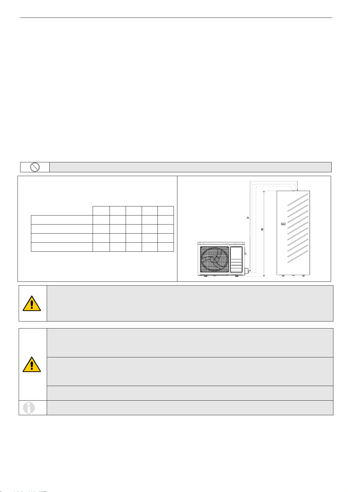
Mod 06 09 12 16
Liquid pipe diameter (Ø) mm 6,35 9,53 9,53 9,53
Gas pipe diameter (Ø) mm 12,7 15,9 15,9 15,9
A Max length of piping m 25 30 30 30
B Max difference level m 15 15 20 20
Do not carry out the connections by using ordinary hydraulic pipes that might contain inside themselves residues of
chips, dirt, or water which can damage the components of the unit and alterate the correct operation of the
equipment.
Use only specific refrigeration copper pipes that should be provided clean and sealed at the ends.
Use only pipes with correct dimensions of diameters; refer to the table of the technical data in the chapter 15.
Cut the pipes with wheel pipes cutter, clutch slowly paying attention for not to crush the pipes when using the tool.
Never use an ordinary hacksaw because shavings could go into the pipe and then circulate in the system which can
seriously damage the components.
After cutting the pipe, please seal immediately the opening on both ends of the roll and cut pipe.
The equipment does not require any additional refrigerant.
The refrigerant pipes should be straight as possible and the necessary bends must have radius more than 300mm.
Plug the opening on the ends of the pipes before inserting them through the hole in the wall.
The refrigerant piping and joints must be thermally insulated to prevent heat loses.
You should avoid the introduction of non-condensable gases (air) into the circuit; otherwise, the pressure becomes
high during operation with the risk of system breaking.
A FITTING KIT PROVIDED WITH THE INDOOR UNIT IS REQUIRED FOR THE CONNECTION OF THE INDOOR UNIT 06
WITH OUTDOOR UNIT 06.
22
Page 24
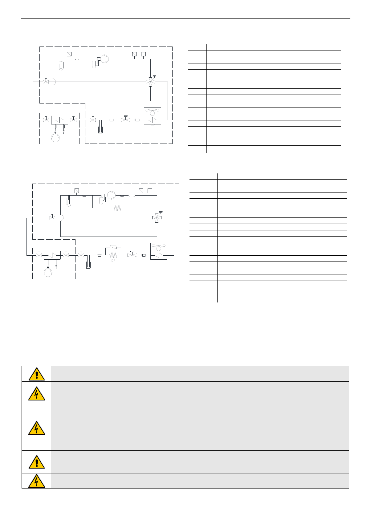
7.6.1 Refrigerant diagram for models 06 and 09
US FLOOR / FLOOR Minichiller inverter Duo
LS
IN
OUT
P
UNITA' INTERNA
INDOOR UNIT
LP HP
C
CLS
LR
DT
FL FL
EEV
UNITA' ESTERNA
OUTDOOR UNIT
ST
Pr
4WV
M
SE
7.6.2 Refrigerant diagram for models 12 and 16
IN
OUT
P
UNITA' INTERNA
INDOOR UNIT
LP
C
ST
LS
FL FL
LR
CLS
DT
NRV
UNITA' ESTERNA
OUTDOOR UNIT
EEV
HP
Pr
OS
4WV
M
SE
C COMPRESSOR
CLS COMPRESSOR LIQUID SEPARATOR
ST COMPRESSOR INLET TEMPERATURE
DT COMPRESSOR OUTLET TEMPERATURE
HP HIGH PRESSURE TRANSDUCER
Pr HIGH PRESSURE FLOW SWITCH
LP LOW PRESSURE TRANSDUCER
LS LIQUID SEPARATOR (only for the model 09)
4WV VALVE FO INVERTING CYCLE
LR LIQUID RECEIVER
EEV ELECTRONIC EXPANSION VALVE
FL FILTER
M AXIAL FAN
SE OUTDOOR AIR TEMPERATURE
P CIRCULATOR ON BOARD UNIT
IN WATER INLET TEMPERATURE
OUT WATER OUTLET TEMPERATURE
C COMPRESSOR
CLS COMPRESSOR LIQUID SEPARATOR
OS OIL SEPARATOR (only for the models 12 and 16)
ST COMPRESSOR INLET TEMPERATURE
DT COMPRESSOR OUTLET TEMPERATURE
HP HIGH PRESSURE TRANSDUCER
Pr HIGH PRESSURE FLOW SWITCH
LP LOW PRESSURE TRANSDUCER
LS LIQUID SEPARATOR
4WV VALVE FO INVERTING CYCLE
LR LIQUID RECEIVER
EEV ELECTRONIC EXPANSION VALVE
NRV NO RETURN VALVE (only on some models)
FL FILTER
M AXIAL FAN
SE OUTDOOR AIR TEMPERATURE
P CIRCULATOR ON BOARD UNIT
IN WATER INLET TEMPERATURE
OUT WATER OUTLET TEMPERATURE
CP CAPILLARY
7.7 ELECTRICAL CONNECTIONS
Check if the power supply meets the unit’s electric nominal data (voltage, phase, frequency) reported on the label in the unit’s
right-side panel. Power supply wiring has to be made according to the wiring diagram enclosed with the unit and according to the
national and international norms in force (provide equipment as general magneto-thermic circuit breaker, differential circuit
breakers for each electric single line, proper grounding for the plant, etc.). Power supply cables, the electric protection and line
fuses have to be sized according to the specifications listed in the wiring diagram enclosed with the unit and in the electrical data
contained in the table of the technical characteristics (see the chapter 15).
WARNING: The supply voltage’s fluctuations cannot exceed ±10% of the nominal value. If this tolerance should
not be respected, please contact our technical department.
WARNING: The power supply should respect the listed limits: failing this, warranty will not be valid immediately.
Before any operation on the unit, be sure that the power supply is disconnected.
Phase, neutral and ground connections should be respected.
Install upstream of each unit an adequate protection and disconnection device of the electric power with delayed
characteristic curve, with at least 3 mm contact opening and with an adequate capacity of breaking and
differential protection.
A good grounding is required; the manufacturer is not responsible for damage caused in case of lack of good
grounding.
Use cables that meet the regulations in force in different countries.
WARNING: The water flow switch of the indoor unit must ALWAYS be connected following the indications listed in
the wiring diagram. Never bridge the water flow switch connections in the terminal board. If the water flow
switch connections may be altered or not properly made, the guarantee will not be valid.
The connections to the terminal blocks should be done only by qualified personnel
23
Page 25
US FLOOR / FLOOR Minichiller inverter Duo
Avoid direct contact with the pipes
Be sure, after about 10 minutes of operation the screws on the power supply terminal block that are well fixed.
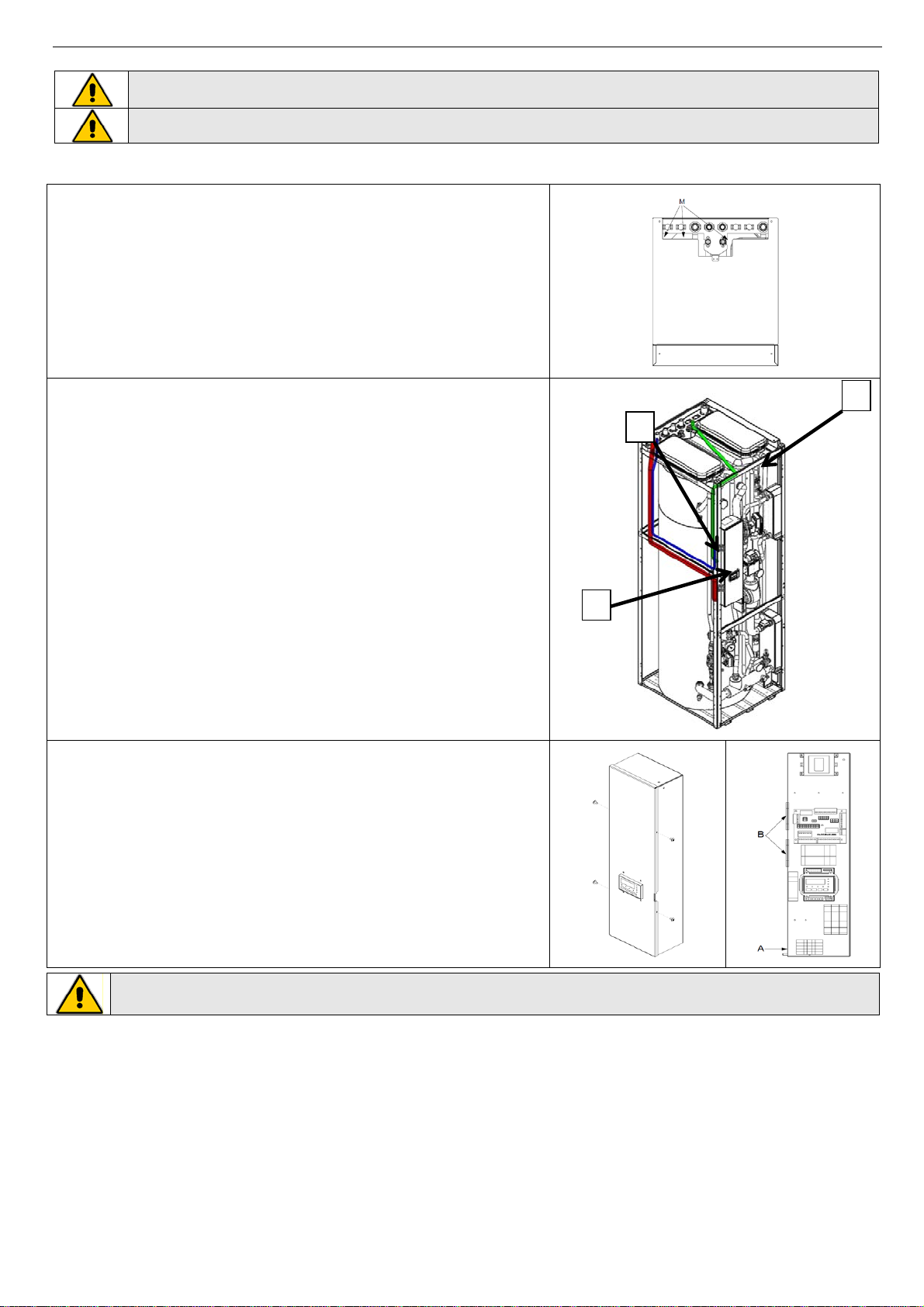
7.7.1 Indoor unit
• The power supply and signal cables should pass along the space between
the metal sheets in the top part of the unit and use the fixing clamps for
fastening.
• Follow along the suggested path cable reported in the image.
• Use a shielded signal cable to reduce/prevent interferences
M. Cables gateway
• The power supply and signal cables should pass along the space between
the metal sheets in the top part of the unit and use the fixing clamps for
fastening.
• Follow along the suggested path cable reported in the image.
• Use a shielded communication cable to reduce/prevent interferences.
P
O
N. Power supply cables inlet
O. Power supply cables outlet (if present)
P. Communication cable gateway with outdoor unit (see Paragraph
7.7.3)
As for the connection P, the communication cable with outdoor unit, it’s
recommend to use a shielded twisted-pair multipolar cable 5x0.75mm
2
and
to pass it as far as possible from the other two connections.
• Remove the mounting screws.
• Remove the cover plate of the electric box.
• Connect the cable to the terminals inside the electric box.
• Please refer to the wiring diagrams given in paragraphs 30.2 for electrical
connections.
A. Power cable inlet
B. Auxiliary connections
WARNING: For allowing the power supply and communication cables to cross easily, it is recommended to remove
the side panels. Prepare then all the connections before any concealed installation.
N
24
Page 26
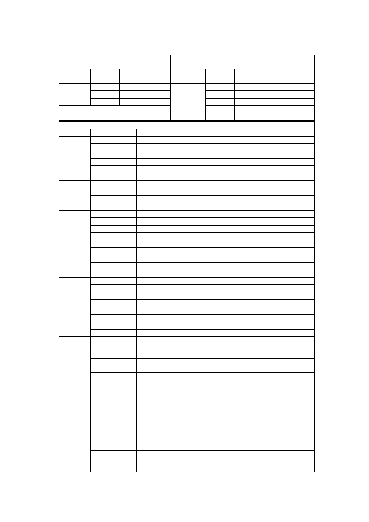
US FLOOR / FLOOR Minichiller inverter Duo
7.7.1.1 Terminal block connections
For getting information on the legend and location of the terminal blocks in the electric box, please see the wiring diagrams in the
Chapter 30.
Power supply terminal block
Single phase system 1-Ph_230Vac + N +PE
Terminal
block
M1
Terminal Description
PE Grounding conductor
L Phase conductor L1 Phase conductor 1
N Neutral conductor L2 Phase conductor 2
Three-phase system 3-Ph _230Vac + N +PE
Terminal
block
M1
Terminal block Auxiliary Board – AB – Indoor unit
Jumper Terminal Description
HP+ 4-20mA ST5 analog input
HP- GND reference signals
CN3
CN4 PWM 1 / 0-10V 1 Analog output 1
CN5 PWM 2 / 0-10V 2 Analog output 2
CN7
CN8
CN8
CN10
CN12
CN14
LP+ 4-20mA ST6 analog input
LP- GND reference signals
DT ST4 analog input / ID5 digital input
12V Power supply 12Vac
AI10 Ratiometric 0-10V analog input
+5V Power supply for ratiometric
AI1 ST3 analog input/ ID4 digital input
AI2 ST2 analog input
AI3 ST1 analog input
AI4 ST9 analog input / ID8 digital input
AD1 ST7 analog input/ ID6 digital input
AD2 ST8 analog input/ ID7 digital input
DI1 ID1 digital input
DI2 ID2 digital input
DI3 ID3 digital input
L Single-phase 230Vac
N NU
DO1 DO1 digital output (single-phase 230Vac)
DO2 DO2 digital output(single-phase 230Vac)
DO3 DO3 digital output (single-phase 230Vac)
DO4 DO4 digital output (single phase 230Vac)
DO5 Phase 230Vac
DO5 Digital output DO5 (Phase 230Vac)
NC1
C1 Phase 230Vac
NO1
I+ / I-
GND
R+ / R-
E+ / E-
NC2
C1 Phase 230Vac
NO2
(Modbus reference mass for connection to outdoor unit)
Modbus signal connection for communication with PC or the Evo Touch
Digital output DO6 (Phase 230Vac)
Normally Closed Changeover Contact
DO6 digital output (Phase 230Vac)
Normally Open Changeover Contact
Connection for communication with outdoor unit
GND reference signals
(unscheduled) accessory
Connection with outdoor unit and GI2
DO7 digital output (Phase 230Vac)
Normally closed changeover contact
Digital output DO7 (Phase 230Vac)
Normally Open changerover contact
For connecting the terminals I-, I+ and GNDR, t’s recommend to use a shielded twisted-pair multipolar cable 5x0.75mm2.
Power supply board
Terminal Description
PE Grounding conductor
L3 Phase conductor 3
N Neutral conductor
Modbus Inverter
Modbus Master
Modbus Slave
25
Page 27
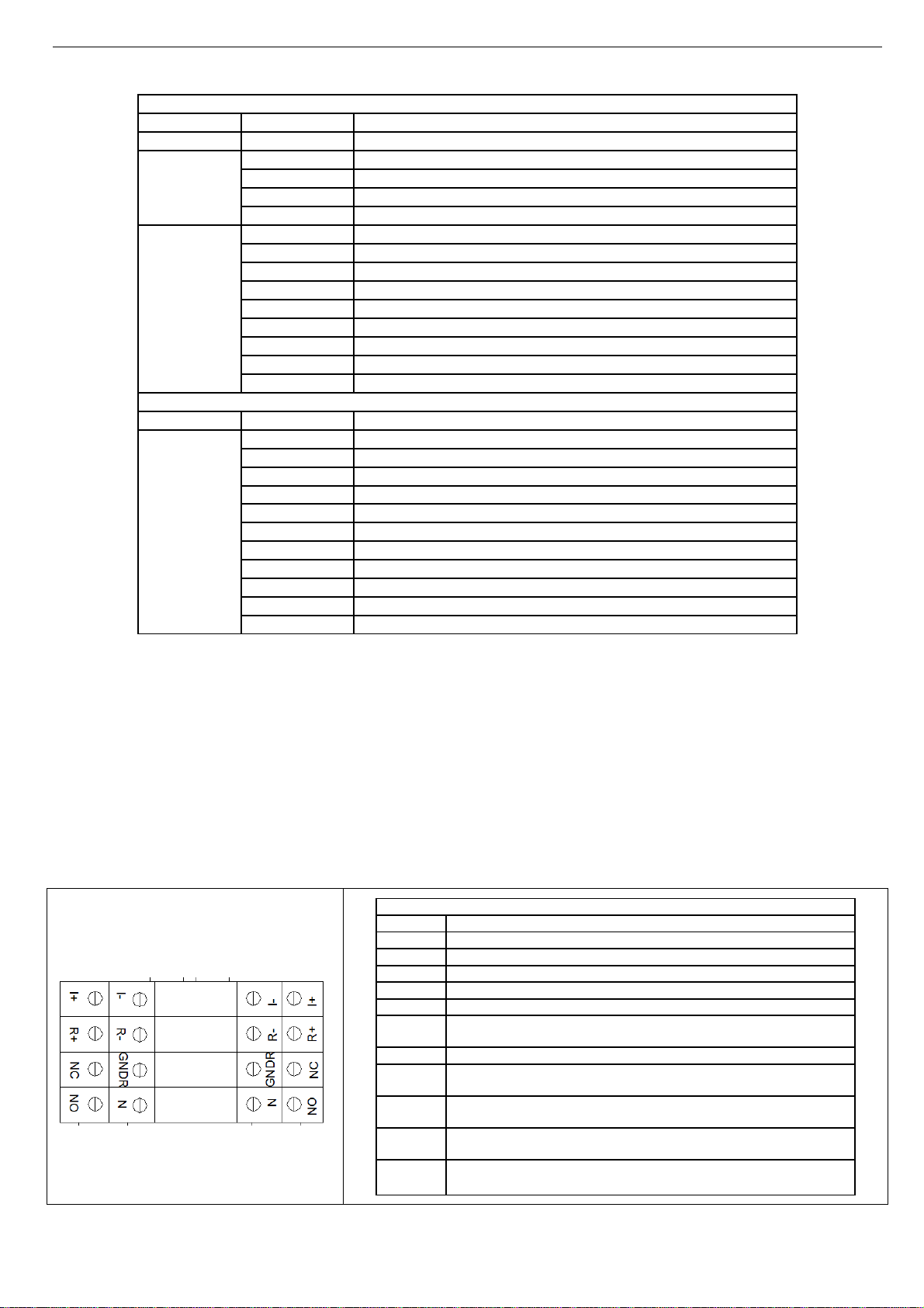
US FLOOR / FLOOR Minichiller inverter Duo
Terminal block Terminals Description
M2 N-3 Neutral conductor for electric heater
LA Phase conductor for auxiliary devices
M3
M4
Terminal block Terminals Description
M5
LB Phase conductor for auxiliary devices
LC Phase conductor for auxiliary devices
PE Grounding conductor for auxiliary devices
N-1 Neutral conductor for auxiliary devices
N-2 Neutral conductor for auxiliary for auxiliary devices
12V Power supply 12Vac
A11 # Neutral for the contactor coil k1 DHW electric heater
A21 # Phase for the K1 contactor coil DHW electric heater
TACS # DHW electric heater thermostat
A12 # Neutral for the K2 contactor coil GI electric heater
A22 # Phase for the K2 contactor coil GI electric heater
TGI # GI electric heater thermostat
KCS # Phase of solar circulator
KN # Neutral of solar circulator
KMO # Normally Open contact for mixing valve
KMC # Normally closed contact for Mixing valve
KDO # Phase of relaunching circulator
KDON # Neutral of relaunching circulator
K1 # Mixing valve discharge sensor
KS1 # Solar panel collector sensor
KS2 # Solar panel storage tank sensor
K2 # Sensor
KPWM # Analog output
Auxiliary power supply terminal block
GI2 # terminal block
7.7.2 Outdoor unit
The connections listed below are standard. Other connections are shown in the Control Manual of the control panel of the
machine US (Cod. 9120523.XX)
• Remove the mounting screws of the cover of the power supply (see the paragraph 7.4.2.2.)
• Connect the cable to the terminals inside the electric box (for the models 12 and 16 you must also remove the cover and the
right-side panel in order to reach the terminal block).
• For electrical connections please refer to the wiring diagrams given in the paragraph 30.3.
7.7.2.1 Terminal block connections
For models 6 and 09 the terminal block is located under the plastic cover on the right side of the unit for the sizes 12
and 16 it is necessary to remove the front-right panel. The terminal block must be connected in compliance with the
following notes (the schema is only for illustration).
Outdoor unit terminal block
Terminal Description
GND Grounding
N1 Neutral
L1 Phase 1
L2 Phase 2 (only for three-phase systems)
L3 Phase 3 (only for three-phase systems)
NO
NNeutral
NC
I+ / I-
R+ / R-
GNDR
(Modbus reference mass for connection with indoor unit)
Power supply (230V AC) general alarm
(closed if the alarm is on)
Power supply (230V AC) general alarm
(closed if the alarm is off)
Modbus Slave
Wiring with indoor unit
Modbus Master
Wiring with indoor unit
GND reference signals
For connecting the terminals I-, I+ and GNDR, t’s recommend to use a shielded twisted-pair multipolar cable 5x0.75mm2.
26
Page 28
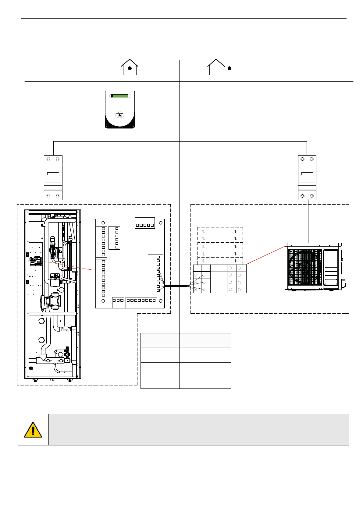
US FLOOR / FLOOR Minichiller inverter Duo
7.7.3 Wiring between indoor and outdoor units
The indoor unit must be connected to the outdoor unit as shown in the below figure.
General electric
panel
TINUROODTUOTINUROODNI
ylppus rewoPylppus rewoP
Protection device
1Ph / 3Ph
INDOOR UNIT
FLOOR - FLOOR-S
Auxiliary Board
AB
CN12
NC1
C1
NO1
I-
I+
GND
RR+
E-
E+
Protection device
OUTDOOR UNIT
06-09-12-16
Terminal block
N
GNDR
I+
I-
R-
R+
NO
NC
GNDR
I-
I+
R-
R+
1Ph / 3Ph
27
Board AB
Indoor unit
Terminal block
Outdoor unit
I+ I+
I- I-
E+
R+
E- R-
GND GNDR
WARNING: Do not confuse on the terminal block of the outdoor unit between the terminals GND (protective earth of
the power supply) with GNDR (ground reference for Modbus connection).
Farther, the shielding of the twisted pair for Modbus signal must be connected at one end to ground terminal
(protective earth terminal) of the unit.
Page 29
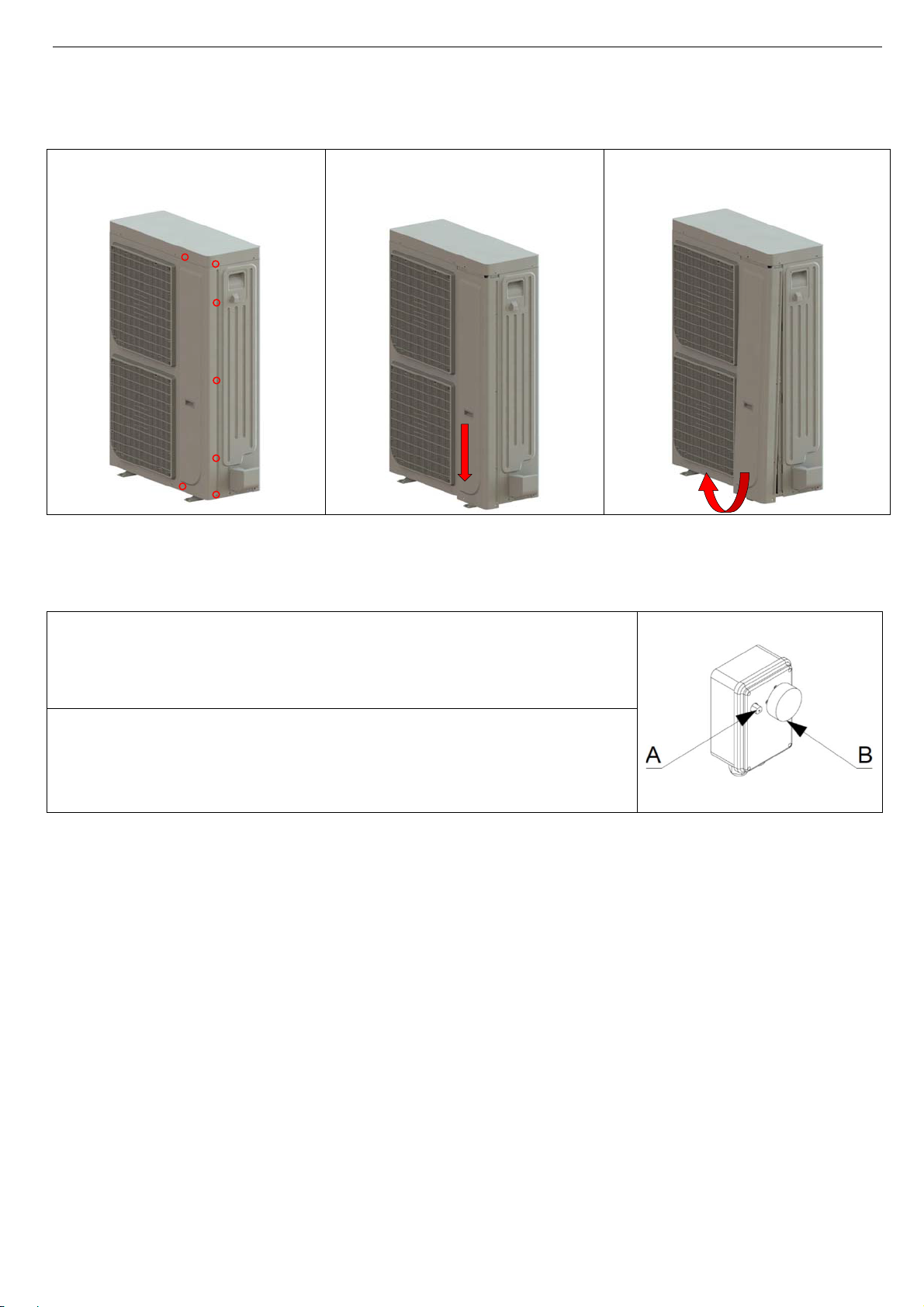
US FLOOR / FLOOR Minichiller inverter Duo
7.7.4 Removal of the front-right side panel of the outdoor unit models 12 and 16
The following illustraon shows the procedure for removing the front-right side panel in order to reach the terminal block in the
models 12 and 16.
1) Remove the fixing screws as indicated
in the figure below.
To replace and secure the front-right side panel follow the same procedure but in reverse.
2) Push down the front-right side panel. 3) Turn front-right side panel in the
direcon of the arrow in order to remove it.
7.7.5 Safety thermostats
When this ELECTRIC HEATER kit is present , there are 2 thermostats installed inside the single box:
A. Manual reset thermostat:
• Opening 90±5°C;
• Manual rest: following the procedure in the Paragraph 27.1, remove the
front panel, unscrew the plug casing on the on thermostats box, push
the red buon with a suitable tool, and replace the plug.
B. Automac reset thermostat:
• Opening 70±4°C;
• Differenal 5±3.5°C
(WARNING: Adjustment knob of the intervenon threshold of the automac thermostat
with factory seng, other values can ensure the proper operaon of the unit)
For some configuraons of the ELECTRIC HEATER kit placed on the models FLOOR and FLOOR-S, you can get two thermostats
boxes, one controlling the temperature on the DHW technical side and the other one for plant side.
28
Page 30
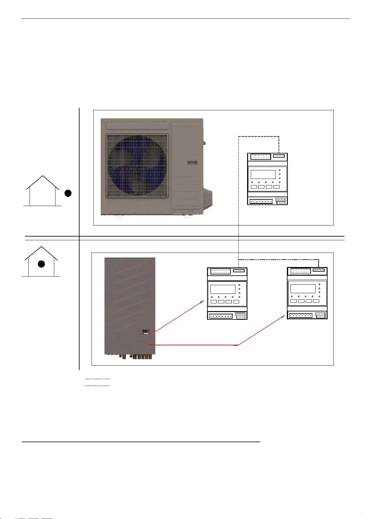
US FLOOR / FLOOR Minichiller inverter Duo
8 SYSTEM STRUCTURE
The system consists in two units:
1) One outdoor unit: US 06-09-12-16 E versions
2) One indoor unit in WALL - FLOOR - FLOOR-S models:
Each unit is equipped with electronic control:
a) CB = (Master) integrated controller on the front panel in the indoor unit;
b) SL1 = (Slave 1) integrated controller in the outdoor unit.
FLOOR-S models are provided with an addional controller in the indoor unit:
c) SL2= (Slave 2), integrated controller situated inside the switchboard in the indoor unit.
SL1
EXTERNAL
UNIT
INTERNAL
UNIT
Collegamento Unità Interna (CB) - GI2 (SL2) / Connections Indoor Unit (CB) - GI2 (SL2)
Collegamento Unità Interna (C B) - Uni tà esterna (SL1) a cura dell'installatore / Connections Indoor Unit (CB) - External Unit (SL1) by the installer
The picture shows a sample connection of the control system between outdoor unit (US 09 model) and indoor unit (WALL model) For any versions of indoor and
outdoor units, the connection is the same.
CB
SL2
CB controller in the indoor unit manages the ModBUS communicaon in the whole system and it is called MASTER because it
establishes which kind of operaon shall be carried out in a precise moment, while SL1 unit and SL2 unit, if present, are considered
as SLAVE because they are managed by the MASTER one.
N.B. This manual describes logics and functions of the CB controller in the indoor unit
29
Page 31
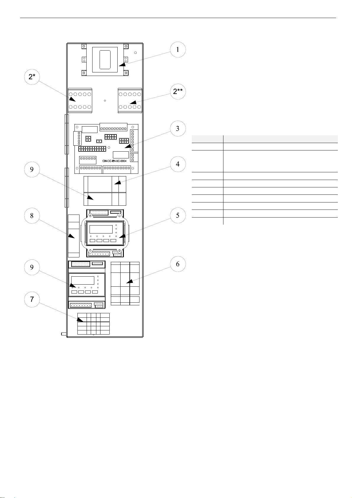
US FLOOR / FLOOR Minichiller inverter Duo
9 SWITCH BOARD LAYOUT IN THE INDOOR UNIT
Position Description
1 Transformer 240V/12V-30VA
4-pole contactor coil 230 V 20A
2
3 Additional board
4 M5 terminals
5 CB controller
6 Fuse holder BCH 38 series
7 M1 terminals – Unit power supply
8 M3 terminals – Auxiliary power supply9 SL2 controller (if present)
*( if DHW heater is present)
**( if the system heater is present)
10 START UP
Before start-up
• Ensure the availability of diagrams and manuals of the installed appliance.
• Check the availability of diagrams electrical and hydraulic diagrams of the plant where the appliance is connected.
• Check if the anti-vibration couplings exist on hydraulic pipes.
• Check if the shut-off valves of the hydraulic circuits are opened.
• Check that the hydraulic circuit has been loaded into required pressure and vented from air.
• Check that all the hydraulic connections are carried out correctly and that all information on the labels is respected.
• Ensure that arrangements have been provided to drain condensate.
• Ensure that power cables and all terminals are well connected.
• Check that the electrical connections have been made according to applicable regulations including grounding.
• The voltage must be specified on the nameplate of the unit.
• Ensure that the voltage is within the tolerance limits of (±10%).
• Check that the refrigerant connections have been made correctly and that the shut-off valves are open.
30
Page 32
US FLOOR / FLOOR Minichiller inverter Duo
• Check that the heating elements of the compressor are powered properly.
• Ensure that there are no gas leaks.
• Before the start up, check that all shutting panels are positioned and fixed with proper screws.
WARNING: The unit must be connected to the electrical network and should be adjusted in STAND-BY mode
(powered) turning on the general switch for a minimum of 12 hours before start up in order to operate the crankcase
heaters of the compressor, for allowing the proper heat to the compressor crankcase (the heaters are automatically
electrified when the switch is closed).The crankcase heaters turns on properly if after some minutes the temperature
of crankcase’s compressor is about 10°C ÷ 15°C higher than ambient temperature.
WARNING: Never switch off the unit (for a temporary stop) by the way of the main switch, this last component
should be used to disconnect the unit from the power supply only for lengthy stoppages (e.g. seasonal stoppages).
Besides, failing the power supply, the crankcase’s resistances are not supplied thus resulting in a possible breakdown
of the compressors once the unit is switched on.
WARNING: Do not modify the internal wiring of the unit otherwise the warranty will terminate immediately.
WARNING: The summer/winter operating mode has to be selected at the beginning of the related season. Frequent
and sudden changes of this operation should be avoided in order to prevent severe damages to compressors.
WARNING: For the first installation and start-up of the unit, make sure that the unit is working correctly in both
cooling and heating modes.
11 INDICATIONS FOR THE USER
Write down the identification data of the unit for to provide them to the service center in the event of a request for assistance.
The identification label of the machine reports the technical data and performance of the equipment.
In case of lost or damage identification label, ask a duplicate to a Technical Service Center.
Tampering with, removal, deterioration of identification label, makes difficult any operation of installation,
maintenance and demand for spare parts.
It is advisable to keep track of the work performed on the unit, so any troubleshooting will be easy to find.
In case of failure or malfunction:
• check the type of alarm to indicate to the service center;
• contact an authorized service center;
• if required by the service center, turn off the unit immediately without resetting the alarm;
• require the use of original spare parts.
12 SHUTDOWNS FOR LONG PERIODS
• Turn off the units from control panel (displayed “OFF”).
• Close the water tap.
• Place the general differential QF switch in “OFF” state.
If the indoor unit is installed in areas of the building subject to low temperatures (attics, basements, etc.) and the
temperature drops below 0°C there is serious danger of frost: provide please a mixture of water and glycol in the
plant system, otherwise drain the water system and the hydraulic circuits of the heat pump.
If it is necessary to add glycol to the hydraulic circuit of the plant, provide a T-fitting with tap downstream of the
non-return valve on the charging/topping-up pipe (see Paragraph 7.5), in order to adapt the glycol concentration.
WARNING: the operation, although it was transient, with water temperatures below +5°C is not guaranteed on the
basis of the limits set out in Paragraph 24.4 . Before you turn the unit on after a long off period, make sure that the
temperature of the mixture of water and glycol is higher than or at least equal to +5°C.
13 MAINTENANCE AND PERIODIC CHECKS
WARNING: All the operations described in this chapter HAVE TO BE CARRIED OUT BY TRAINED STAFF ONLY. Before
any operation or before acceding to the inner components of the unit, be sure that the power supply is not
connected. The compressor’s heads and discharge piping are usually at high temperature levels. Be very careful when
operating in their surroundings. Aluminum coil fins are very sharp and can cause serious wounds. Be very careful
when operating near them. After servicing operations, re-install the cover panels, and fix them by means of screws.
The refrigerant circuits must not be filled with refrigerant gas other than that indicated on the nameplate. The use
of a different refrigerant can cause severe damage to the compressor.
It is forbidden to use refrigerant oils other than those specified in this manual. The use of different oil can cause
serious damage to the compressor.
The top part and discharge pipes of the compressor operating at high temperatures. Be sure to let the unit to
become cool before beginning any maintenance work.
31
Page 33
US FLOOR / FLOOR Minichiller inverter Duo
Be careful when working near the condensing coils.
The aluminum fins are very sharp and can cause serious injuries.
After the maintenance operations, close the panels fixing them with screws.
It is a good rule to carry out periodic checks in order to verify the proper operation of the unit.
OPERATION
Charging of the water circuit. x
Presence of bubbles in the water circuit. x
Check the proper working of the safety and control devices (indoor and outdoor units) x
Check if there is a possible oil leakage from compressor (outdoor unit). x
Check if there is a possible water leakage from the hydraulic circuit (indoor unit). x
Check the proper working of the flow switches (outdoor unit). x
Check out if the crankcase resistances are supplied and working properly (outdoor unit). x
Clean the metallic filters of the hydraulic circuit. x
Clean the finned coil by means of compressed air or water jet (outdoor unit). x
Check if all the terminals on the electric board as well as on the terminals of the compressor
are properly fixed. Clean from time to time the remote control switch’s sliding and fixed
contactors (indoor and outdoor units).
Tightening of hydraulic connections. x
Check the tightening and the balancing of the fan blades (outdoor unit). x
Correct voltage. x
Correct power absorption. x
Check the refrigerant charge. x
Check the operating pressure, and superheat and sub-cooling x
Check of the efficiency of circulation pump. x
Check the expansion tank. x
If the unit should be out of service for a long period, discharge water from the piping and from
heat exchanger. This operation is necessary if, during seasonal stoppages, ambient
temperature is expected to go down below the freezing point of the employed fluid.
1
month 4 month6 month
x
x
13.1 ENVIRONMENTAL PROTECTION
According to the norms dealing with the use of depleting stratospheric ozone substances, it is forbidden to release refrigerants
fluids in the atmosphere. They have to be collected and delivered to the seller or to proper gathering points at the end of their
operating life. Refrigerant R410A is mentioned among controlled substances and for this reason it has to be subjected to the
mentioned norms. A particular care is recommended during service operations in order to reduce as much as possible any
refrigerant loss.
14 WHEN THE UNIT GOES OUT OF SERVICE
Once the unit is arrived at the end of its life cycle and needs to be removed or replaced, the following operations are recommended.
• the refrigerant has to be recuperated by trained people and sent to a proper collecting centre;
• compressors’ lubricating oil has to be collected and sent to a proper collecting centre;
• the frame and the various components, if not serviceable any longer, have to be dismantled and divided according to their
nature, particularly copper and aluminum, which are present in conspicuous quantity in the unit. These operations allow easy
material recover and recycling process, thus reducing the environmental impact.
32
Page 34
US FLOOR / FLOOR Minichiller inverter Duo
15 TECHNICAL DATA
15.1 PERFORMANCE DATA
Model US
Model US
Twin Rotary
DC inverter
Twin Rotary
DC inverter
Cooling
Heating
PERFORMANCE DATA Units
Cooling capacity (1) kW 2,48 - 5,14 - 5,62* 4,44 - 8,33 - 8,93* 4,93 - 11,69 - 12,58* 6,48 - 13,15 - 14,72*
Input power (1) kW 1,28 2,17 2,88 3,45
EER (1) W/W 4,01 3,83 4,07 3,81
Cooling capacity (2) kW 1,79 - 3,95 - 4,45* 3,22 - 6,16 - 7,59* 3,57 - 7,88 - 10,20* 4,58 - 9,91 - 12,10*
Input power (2) kW 1,30 2,05 2,60 3,38
EER (2) W/W 3,04 3,01 3,04 2,93
ESEER (5) W/W 6,17 5,87 6,31 5,93
Heating capacity (3) kW 2,62 - 5,81 - 6,24* 4,71 - 9,04 - 9,87* 5,14 - 12,52 - 13,32* 6,63 - 14,18 - 15,84*
Input power (3) kW 1,37 2,18 2,93 3,46
COP (3) W/W 4,25 4,15 4,27 4,09
Heating capacity (4) kW 2,49 - 5,49 - 5,81* 4,47 - 8,78 - 9,25* 4,87 - 11,80 - 12,58* 6,22 - 13,77 - 14,51*
Input power (4) kW 1,61 2,65 3,38 4,26
COP (4) W/W 3,41 3,32 3,50 3,23
SCOP (6) W/W 3,92 3,85 3,89 3,82
06 09 12 16
Operating conditions:
(1) Cooling: Outdoor air temperature 35°C; inlet/outlet temperature 23/18°C.
(2)
Cooling: Outdoor air temperature 35°C; inlet/outlet temperature 12/7°C.
Heating: Outdoor air temperature 7°C DB 6°C WB; inlet/outlet temperature 30/35°C.
(3)
(4) Heating: Outdoor air temperature 7°C DB 6°C WB.; inlet/outlet temperature 40/45°C.
(5) Cooling: water temperature inlet/outlet 23/18°C
(6) Heating normal climatic condition; T
=-7°C; temperature inlet/outlet 30/35°C
biv
(*) With Hz max operation already enabled by factory default, can be disabled only with the optional control panel Evo Touch (Unscheduled)
N.B. The performance data are indicative and could be subject to change. In addition, the performances declared in apex (1), (2), (3) and (4) refer to the
instantaneous power according to EN 14511.
The declared data stated in the apex (6) is determined according to the UNI EN 14825
15.2 OUTDOOR UNITS
TECHNICAL DATA Units
Power supply 230V/1/50Hz 230V/1/50Hz 230V/1/50Hz 400V/3P+N+T/50Hz
Electrical data
Compressor
Fan motor
Refrigerant
Refrigerant piping
Noise Sound pressure (6) dB(A) 44÷50 45÷53 46÷54 46÷54
Dimensions and
weight
Max. power input kW 2,70 4,49 5,59 7,77
Max. starting current A 7,7 12,8 16,0 7,4
Max. current input A 11,8 19,6 24,4 11,3
Brand
Type
Number 1 1 1 1
Input power in cooling mode (1) kW
Input power in cooling mode (2) kW
Input power in heating mode (3) kW
Input power in heating mode (4) kW
Refrigerant oil (type, quantity) mL ESTER OIL VG74, 480 ESTER OIL VG74, 820 FV50S, 1070 FV50S, 1400
Type DC Brushless Motor DC Brushless Motor DC Brushless Motor DC Brushless Motor
Number 1 1 2 2
Rated power input kW 0,156 0,188 0,144 (×2) 0,180 (×2)
Rated running current A 0,68 0,82 0,63 (×2) 0,79 (×2)
Speed r/min 900 900 800 1000
Max. air flow m3/s 1,08 1,63 2,11 2,59
Type R410A R410A R410A R410A
Refrigerant charge (5) kg 1,35 1,90 3,50 3,40
Pressure design (high/low) MPa 4,2/2,7 4,2/2,7 4,2/2,7 4,2/2,7
Liquid side / Gas side mm 6,35/12,7 9,53/15,9 9,53/15,9 9,53/15,9
Max. Refrigerant pipe length m 25 30 30 30
Max. difference in level m 15 15 20 20
Dimensions (L×A×P) mm 916×719×360 975×861×355 1024×1402×448 1024×1402×448
Maximum dimensions of the packing (L×A×P)mm 1090x828x490 1090x978x490 1095x1525x490 1095x1525x490
Net/Gross weight kg 50/61 66/77 109/122 114/127
Operating conditions:
(1) Cooling: Outdoor air temperature 35°C; inlet/outlet water temperature 23/18°C.
(2) Cooling: Outdoor air temperature 35°C; inlet/outlet water temperature 12/7°C.
(3) Heating: Outdoor air temperature 7°C DB 6°C WB; inlet/outlet water temperature 30/35°C.
(4) Heating: Outdoor air temperature 7°C DB 6°C WB; inlet/outlet temperature 40/45°C.
(5) Refrigerant charge valid until 3m of distance between indoor and outdoor units. Above 3m, add 20g/m of refrigerant for the model 06 and 50g/m of refrigerant
for the models 09-12-16. Less than 3m, take out 20g/m of refrigerant for the model 06 and 50g/m of refrigerant for models 09-12-16. The minimum distance
between indoor and outdoor units is 1m.
(6) Sound pressure level measured at 1m from the unit, in free field, according to ISO 3746.
N.B. The performance data shown is indicative and could be subject to change.
06 09 12 16
GMCC GMCC Mitsubishi Mitsubishi
Single Rotary
DC Inverter
1,16 2,03 2,63 3,11
1,17 1,90 2,35 3,05
1,25 2,04 2,68 3,12
1,50 2,50 3,13 3,92
Twin Rotary
DC Inverter
33
Page 35
US FLOOR / FLOOR Minichiller inverter Duo
15.3 INDOOR UNITS
15.3.1 Models FLOOR/FLOOR-S
TECHNICAL CHARACTERISTICS Unit
Indoor unit coupled with a moto-condensing unit size:
Hydraulic circuit
DHW-R circuit
Refrigerant circuit
Noise Sound pressure (6) dB(A) 22 28
Dimensions and
weight
Water flow (3) m3/h
Available head pressure (3) kPa
Available head pressure (3) W
Max. input power of water pump W
Max. input current of water pump A
Energy Efficiency Index (EEI) pump ≤ 0,21 ≤ 0,23
DHW technical side puffer tank L 190 190
Plant puffer tank L 40 40
DHW technical side expansion vessel L 8 8
Plant side expansion vessel L 8 8
Hydraulic connections inch 1”M 1”M
Minimum volume of water L 18 25 35 45
Maximum supplied flow rate for DHW side L/min 40 40
Minimum water flow for start-up L/min 3 3
Maximum capacity of the primary pump W
Maximum current of the primary pump A
Energy Efficiency Index (EEI) pump ≤ 0,20 ≤ 0,20
Hydraulic connections inch 3/4”M 3/4”M
Liquid side connections inch 1/4” SAE 3/8” SAE 3/8” SAE 3/8” SAE
Gas side connections inch 1/2” SAE 5/8” SAE 5/8” SAE 5/8” SAE
Dimensions (LxAxP) mm 595x1789x700 595x1789x700
Maximum dimensions of the packing mm 695x1961x800 695x1961x800
Weight in operation (FLOOR/FLOOR-S) kg 399 / 418 406 / 425
Net weight (FLOOR/FLOOR-S) kg 158 / 175 163 /180
Gross weight (FLOOR/FLOOR-S) kg 173 / 190 178 / 195
FLOOR/FLOOR-S 06-09 FLOOR/FLOOR-S 12-16
06 09 12 16
1,00 1,55 2,15 2,44
67 48 58 34
62 75 137 137
75 140
0,60 1,05
45 45
0,44 0,44
Model
(3) Heating: Outdoor air temperature 7°C DB 6°C WB; inlet/outlet temperature 30/35°C.
(6) Sound pressure level measured at 1m from the unit in free field, according to ISO 3744.
WARNING: The minimum temperature allowed for storing the units is 5°C.
34
Page 36
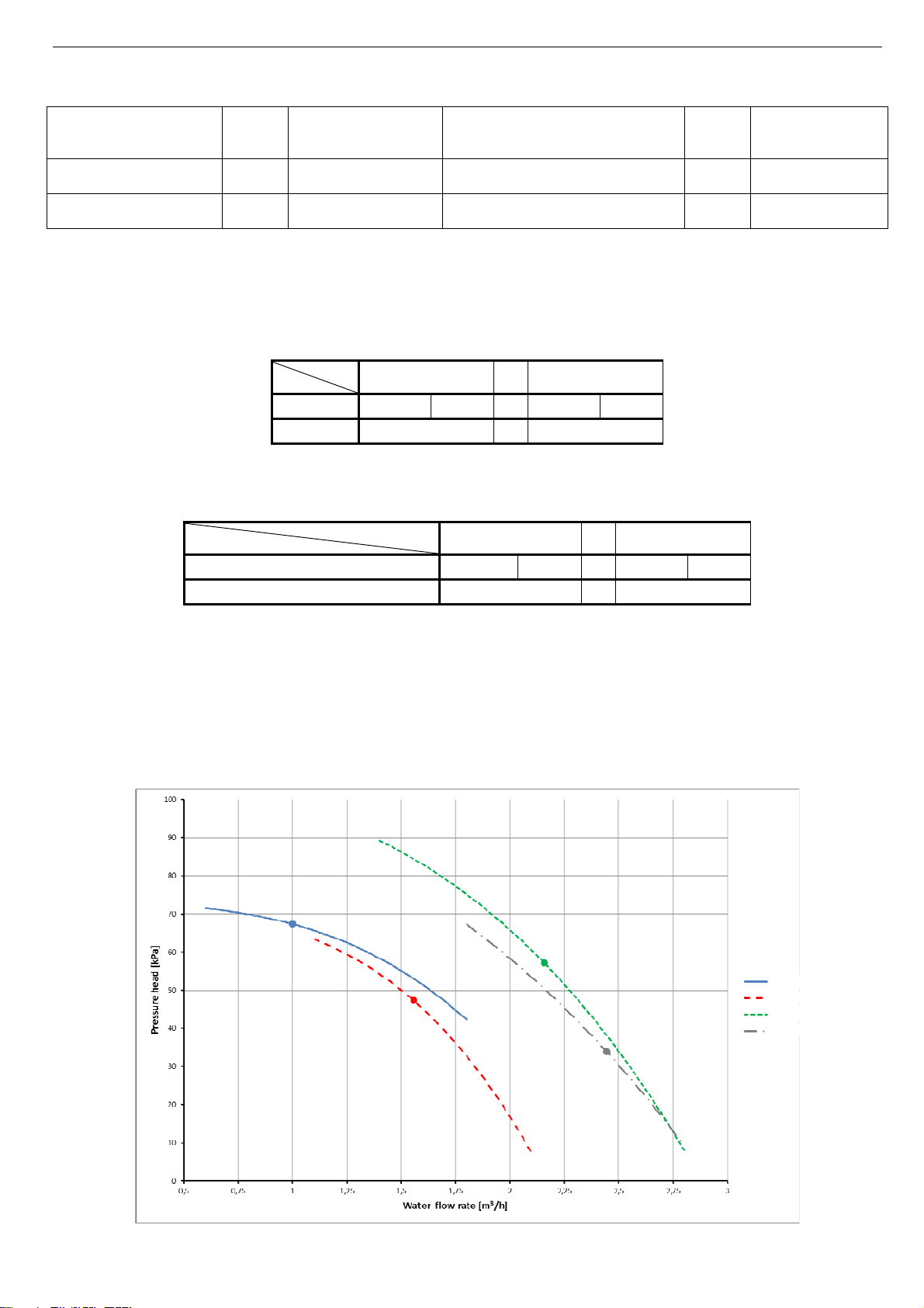
US FLOOR / FLOOR Minichiller inverter Duo
16 ELECTRIC DATA
Power supply of circulator and
Power supply of the unit V/~/Hz 230/1/50*-400/3/50**
Outdoor unit control board
circuit
Indoor unit control board
circuit
V/~/Hz 12/1/50 Outdoor fans power supply V/~/Hz 230/1/50
V/~/Hz 12/1/50 Electric heaters power supply V/~/Hz
* For the single-phase indoor units and for outdoor units of the models 06, 09 and 12.
** For the three-phases indoor units and for the outdoor unit of the model 16.
Note: Electric data may change for updating the manual. It is therefore necessary to refer always to the technical data label
sticked on the right-side panel of the unit.
16.1 MAXIMUM POWER CONSUMPTION/MAX. INPUT CURRENT OF THE INDOOR UNITS 06-09
diverng valve
indoor unit
V/~/Hz 230/1/50
See the power
supply of the unit
Model
E-heater
NOT PRESENT 0,13 kW 1,06 A 0,21 kW 1,66 A
Power supply 230V/1/50Hz 230V/1/50Hz
The electrical data of the outdoor and indoor units are set to scale the size of the circuit breakers and power supply cables. You have to add the input power of
the outdoor unit (see Paragraph 15.2) to that of the indoor unit this depending on the installed electric heater kit.
FLOOR 06-09 FLOOR-S 06-09
16.2 MAXIMUM POWER CONSUMPTION / MAXIMUM INPUT CURRENT OF THE INDOOR UNITS 12-16
Eectric heater
Model
Power supply 230V/1/50Hz 230V/1/50Hz
The electrical data of the outdoor and indoor units are set to scale the size of the circuit breakers and power supply cables. You have to add the input power of
the outdoor unit (see Paragraph 15.2) to that of the indoor unit which depends on the installed electric heater kit.
FLOOR 12-16 FLOOR-S 12-16
A 11,2 Wk 72,0 A 15,1 Wk 91,0 TNESERP TON
17 PUMPS PERFORMACE CURVES
The characterisc curves corresponding to prevalence-water flow rate without head losses of the hydronic kit, which is composed
of the components described in Paragraph 6.10 are shown below. The opmal operang points of the different models are shown
on the following curve according to the cond
The plant must be designed so as to ensure the nominal water flow rate corresponding to the operang points indicated below.
ions indicated in the apex 3 of the paragraph 15.3.
35
US 06
US 09
US 12
US 16
Page 37
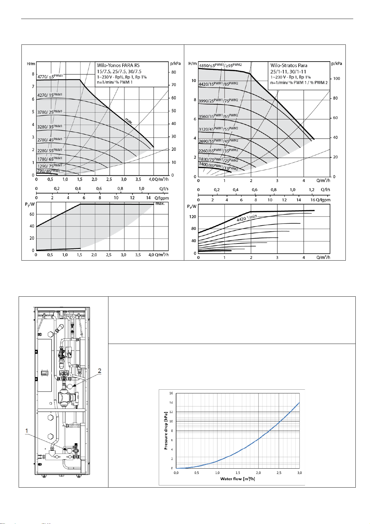
US FLOOR / FLOOR Minichiller inverter Duo
18 CIRCULATOR PUMPS CURVES
mod. US 06 E- US 09 E
mod. US 12 E- US 16 E
19 READING OF THE INDOOR UNIT MANOMETERS
Each indoor unit is equipped with two manometers.
The difference between the manometers (1 and 2) reading can be used as approximate value
for verifying the water flow rate/pressure head when the unit works on the plant (so when the
3-way valve diverts the flow to the le side on the line A).
To the difference of manometers value you should subtract the pressure drop of the 3-way
valve for geng an approximate value of the available pressure head of the plant.
The characterisc curve corresponding to the Head pressure versus Water flow rate of the
three-way diverter valve, whose values should be deducted at the manometric readings for
verifying with sufficient accuracy the available stac pressure of the plant system at the
nominal operang points marked in the curves of Chapter 17.
It is recommended for safety to remove an addional 5% from the obtained values.
36
Page 38
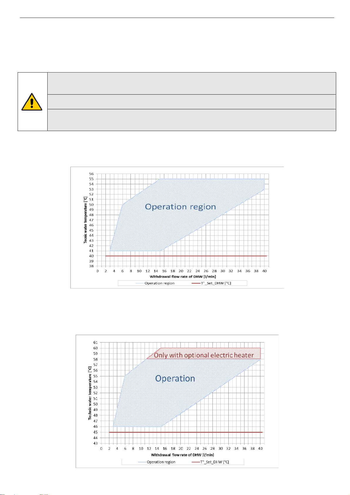
US FLOOR / FLOOR Minichiller inverter Duo
20 DHW INSTANTANEOUS PREPARER
Here below are indicated the operating regions of the instantaneous DHW preparer versus the temperature of the primary circuit
(DHW temperature of technic side) and the water flow rate of the secondary circuit (DHW withdrawal rate), for different values of
the set temperature of domestic hot water (T"_Set_DHW).
The region of operation corresponding to the alone optional electric heater is indicated with red dashed lines.
WARNING: It is necessary to install on the DHW line between the instantaneous preparer and the mixers of
domestic hot water, of an anti-scald thermostatic valve calibrated at 45°C.
Otherwise there is a serious risk of burning and severe scalding.
WARNING: Make sure that there are no air bubbles in the water supply inlet; otherwise the flow meter will not
work properly. Therefore a relief valve or an air vent should be installed on the mains water inlet pipe.
WARNING: The minimum water flow rate of the secondary circuit (water supply) required for the system startup is
3 liters/min. The maximum water flow rate of the secondary circuit should not exceed 40 liters/min, the system
goes wrong over this value.
T”_Set_DHW=40°C
T”_Set_DHW=45°C
37
Page 39
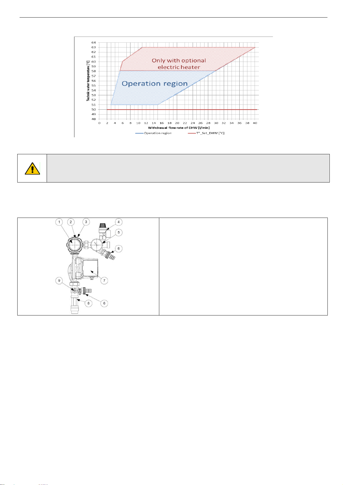
US FLOOR / FLOOR Minichiller inverter Duo
T”_Set_DHW=50°C
21 SOLAR GROUP (MODELS FLOOR-S)
WARNING: It is recommended after doing the lling/topping up/washing to replace the supplied hose connector
with the respective plugs. This can minimize the risk of water dripping and boiling glycol. Keep the supplied hose
connectors for future operations of topping up and cleaning.
The models FLOOR-S include the kit for managing the solar energy source composed of the inlet (return from the plant
circuit) and outlet pipes and group for forced circulaon with high efficiency circulator consisng of: safety group, manometer,
integrated check and ball valves and a flow regulator (2 ÷ 12 L/min). This group allows the charging/washing/maintenance of the
circulator without necessarily of evacuang the plant circuit, through the closing of the outlet side ball valve.
Main components of the Solar Group:
1) Thermometer
2) Knob
3) Outlet ball valve with check valve
4) 6 bar relief valve
5) 0-10 bar manometer
6) Water tap ½” for charging/discharging/washing
7) Circulator
8) Flow controller with graduated scale
9) Calibraon pin for flow controller
38
Page 40
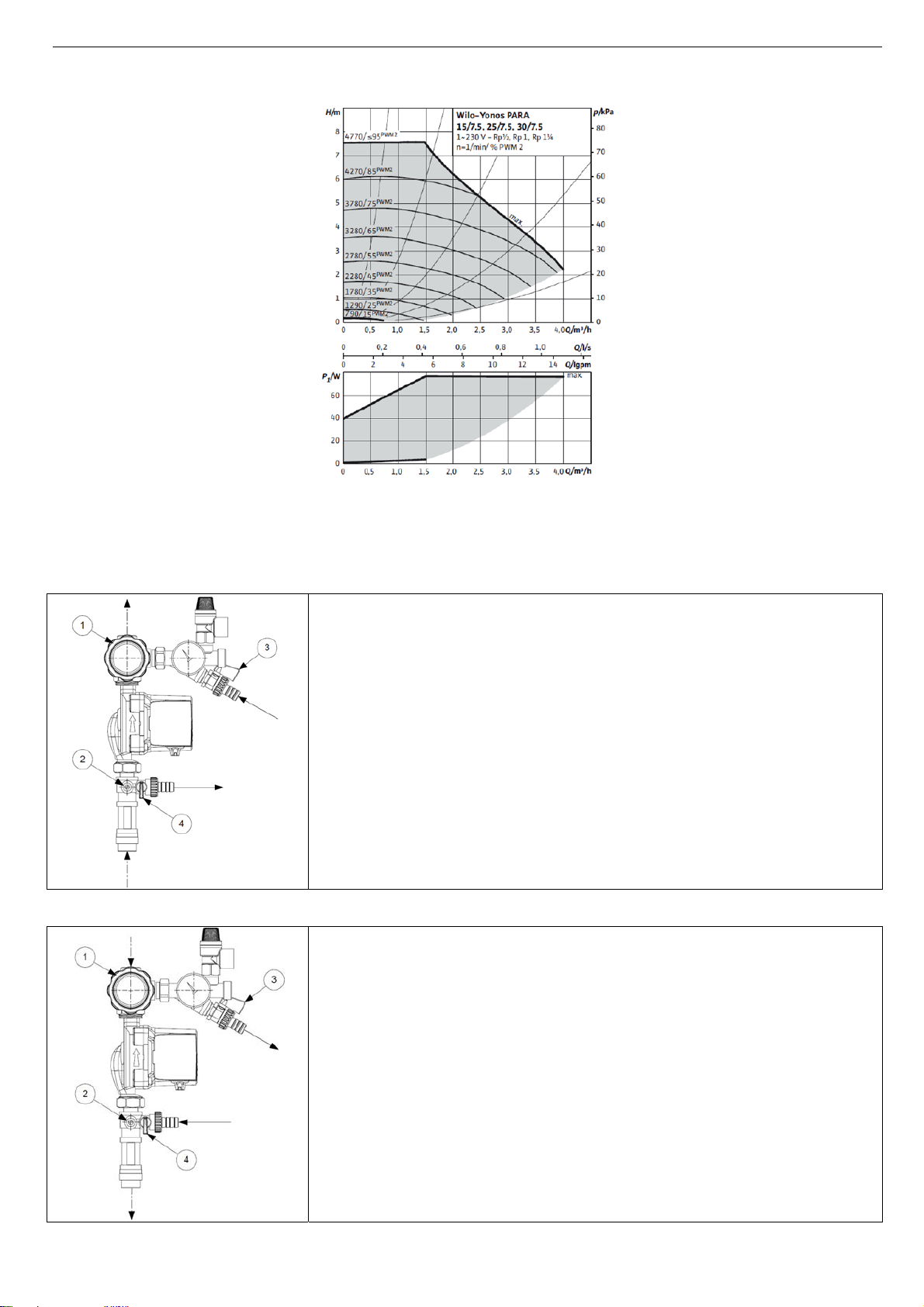
US FLOOR / FLOOR Minichiller inverter Duo
21.1 CIRCULATOR CURVE
21.2 CALIBRATION OF THE WATER FLOW BY USING THE FLOW CONTROLLER
Thanks to the mounted solar group, you can adjust the desired flow rate in the solar plant by rotating slowly the pin valve of the
flow regulator leading the lower end of the float to overlap the reference mark of the graduated scale.
21.3 LOADING OF THE PLANT CIRCUIT
• Close the ball valve of the outlet side (1) by rotating the knob 90 degrees clockwise
and close the flow regulator valve (2) (horizontal calibration pin).
• Connect the needed pipes to the supplied hose pipe joint connectors 14 mm that are
installed near the safety group and the flow regulator. Open the valves (3 and 4).
• Introduce the thermal carrier fluid from the valve of the safety group (3) and use the
second (4) to evacuate the residual air.
• When the sufficient time has elapsed for the total evacuation of the air from the
circuit, close the water flow regulator valve (4) and then to the safety group (3).
• Open again the ball valve and reset the flow regulator valve on the desired flow rate
as described in Paragraph 21.2.
21.4 WASHING OF THE PLANT
39
• Close the ball valve of the outlet side (1) by rotating the knob 90 degrees clockwise
and close the flow regulator valve (2) (horizontal calibration pin).
• Connect the needed pipes to the supplied hose pipe joint connectors 14 mm that are
installed near the safety group and the flow regulator. Open the valves (3 and 4).
• Introducing the fluid from the valve located near the flow regulator (4) and use the
second (3) for the collecting the fluid that is used for washing the plant circuit.
• When the sufficient time has elapsed for washing the plant circuit, close at first the
safety group (3).and then the water flow regulator valve (4)
• Open again the ball valve and reset the flow regulator valve on the desired flow rate
as described in Paragraph 21.2.
Page 41
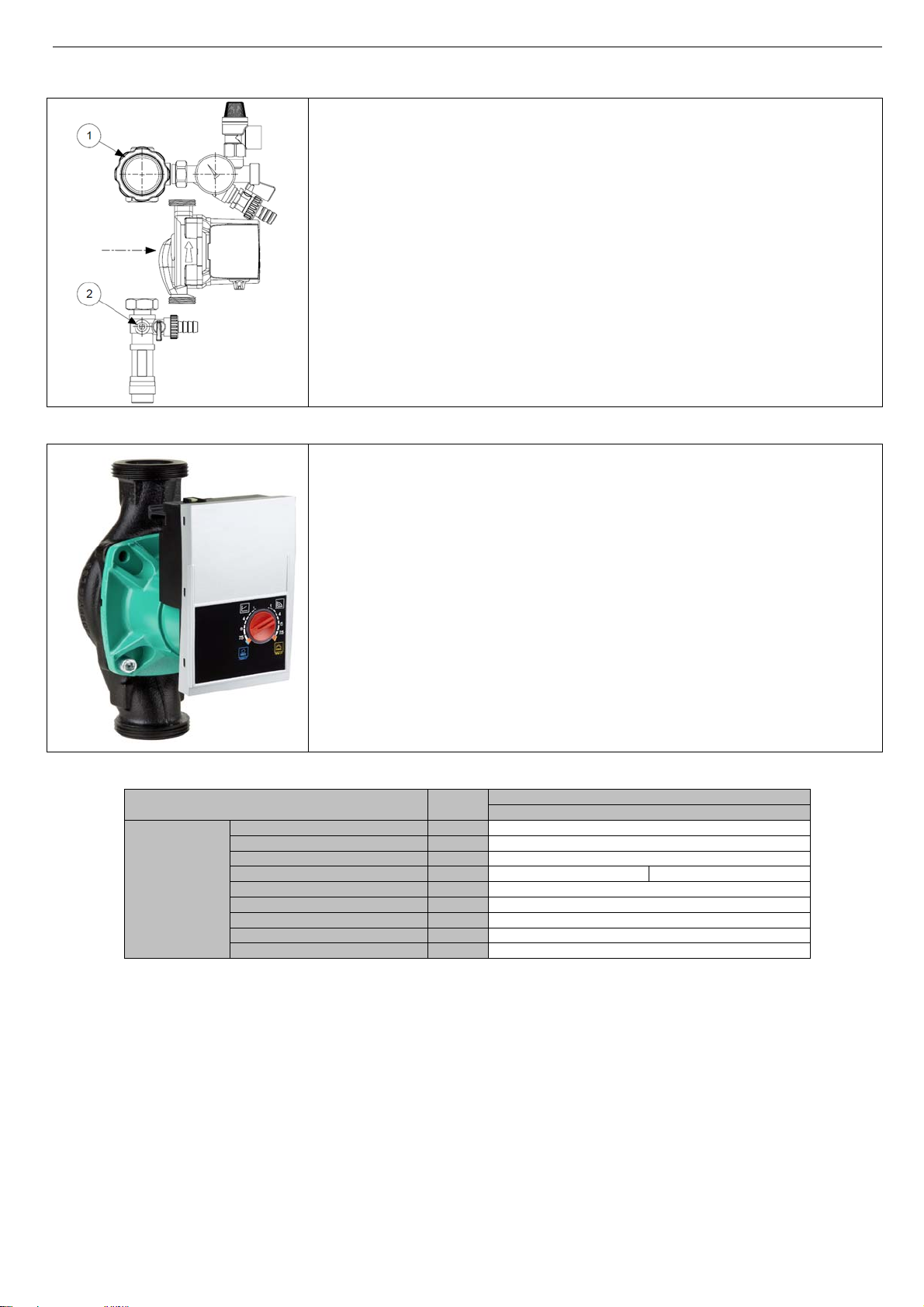
US FLOOR / FLOOR Minichiller inverter Duo
21.5 MAINTENANCE OF THE CIRCULATOR PUMP
For removing and/or working on the circulator pump you don’t need necessarily to
evacuate the plant circuit, just stop the fluid to flow from both upstream and
downstream sides by closing the ball valve (1) (by rotating the knob clockwise) and
closing the flow regulator valve (2) (horizontal calibration pin).
21.6 FACTORY SETTINGS OF THE CIRCULATOR PUMP
The circulator pump is already factory set for optimal operation.
The factory setting requires rotating the slot of the red knob at the blue symbol position
showing the indication of the floor plant (rotating the knob completely counter
clockwise).
It is not recommended to change this setting.
21.7 TECHNICAL CHARACTERISTICS
TECHNICAL CHARACTERISTICS Unit
Maximum water flow m3/h
Maximum pressure of solar circuit bar 6
Maximum temperature °C 120
Solar circuit
Maximum solar surface m2 20 for PLAN collector 15 for collector under vacuum
Solar exchange coil surface m2
Maximum head of the pump kPa
Maximum power of the pump W
Maximum absorbed current of the pump A
Energy Efficiency Index (EEI) pump ≤ 0,21
22 OPTIONAL DHW TECHNICAL SIDE BOILER KIT
Model
FLOOR-S
0,7
0,7
74
75
0,60
The indoor unit in all its versions can be coupled to other external energy source in addition to the solar energy source, such as:
gas boiler, pellet boiler and any other energy source that it is implementable in the control with the characteristics of having a
proper circulator and working with a variable ∆T without exceeding 20-25°C. The kit provides the internal pipes of connection
between the DHW technical side puffer tank and attacks disposed for the installation. The installer must provide the required
hydraulic connections for connecting the indoor unit with the auxiliary energy source as described in Paragraph 7.4.2, and control
setting as described in the manual cod. 9120523.XX.
40
Page 42
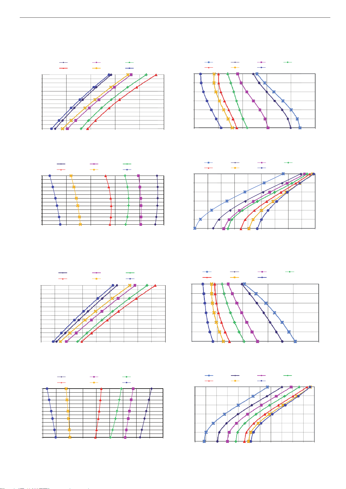
23 PERFORMANCE
US FLOOR / FLOOR Minichiller inverter Duo
US 06 E
[°C]
[°C]
Temperatura a cqua out
Outlet wa te r temperature
[°C]
[°C]
Outlet water temperatur e
Temperatura a cqua out
aria-air
aria-air
45°C
aria-air
30°C
18
17
16
15
14
13
12
11
10
9
8
7
6
5
3,0
18
17
16
15
14
13
12
11
10
9
8
7
6
5
0,6
3,5
aria-air
45°C
aria-air
30°C
0,8
Potenza ass orbita
Power input
Capacità frigorifera
Cooling
4,0
capacity[kW]
aria-air
aria-air
1,0
in
cooling
aria-air
40°C
aria-air
25°C
4,5
[kW]
40°C
25°C
1,2
in
refrigerazione
[kW]
aria-air
35°C
aria-air
20°C
55
[°C]
50
[°C]
45
40
35
30
Temperatura acqua out
Outlet water temperature
25
4,0
[kW]
5,0
aria-air 35°
aria-air
1,4
20°C
C
5,5
1,6
55
[°C]
50
[°C]
45
40
35
30
Temperatura acqua out
Outlet water temperature
25
1,1 1,2 1,3 1,4 1,5 1,6 1,7 1,8 1,9 2,0
aria-air
4,5
aria-air
aria-air
12°C
-7°C
12°C
-7°C
aria-air
7°C
aria-air
-10°C
5,0
Capacità termica [kW]
Heating capacity [kW]
aria-air
7°C
aria-air
-10°C
Potenza assorbita
Power input
in
in
pompa
heating
5,5
[kW]
aria-air
aria-air
aria-air
aria-air
di
2°C
-15°C
2°C
-15°C
calore
[kW]
aria-air
-2°C
6,0
aria-air
-2°C
6,5
US 09 E
18
17
16
[°C]
15
14
13
12
11
acqua out [°C]
10
Outlet water temperature
Temperatura
[°C]
[°C]
Temperatura a cqua out
Outlet wa te r temperature
aria-air
45°C
aria-air
30°C
9
8
7
6
5
4,5 5,0 5,5 6,0 6,5 7,0 7,5 8,0 8,5 9,0
18
17
16
15
14
13
12
11
10
9
8
7
6
5
1,0 1,2 1,4 1,6 1,8 2,0 2,2 2,4 2,6 2,8
Capacità frigorifera
Cooling
aria-air
45°C
aria-air
30°C
Potenza ass orbita
Power input
aria-air
aria-air
capacity[kW]
aria-air
40°C
aria-air
25°C
in
refrigerazione
in
cooling
[kW]
40°C
25°C
[kW]
[kW]
aria-air
aria-air
aria-air
aria-air
35°C
20°C
35°C
20°C
aria-air
aria-air
12°C
-7°C
aria-air
aria-air
7°C
-10°C
aria-air
aria-air
2°C
-15°C
aria-air
-2°C
55
[°C]
50
[°C]
45
40
35
30
Temperatura acqua out
Outlet water temperature
25
7,5
8,0
aria-air
aria-air
12°C
-7°C
8,5
Capacità termica [kW]
Heating capacity [kW]
aria-air
7°C
aria-air
-10°C
9,0
aria-air
aria-air
9,5
10,0
2°C
-15°C
aria-air
-2°C
55
[°C]
50
[°C]
45
40
35
30
Outlet water temperature
Temperatura acqua out
25
1,6 1,8 2,0 2,2 2,4 2,6 2,8 3,0 3,2 3,4 3,6 3,8
Potenza assorbita
Power input
in
in
heating
pompa
[kW]
di
calore
[kW]
41
Page 43
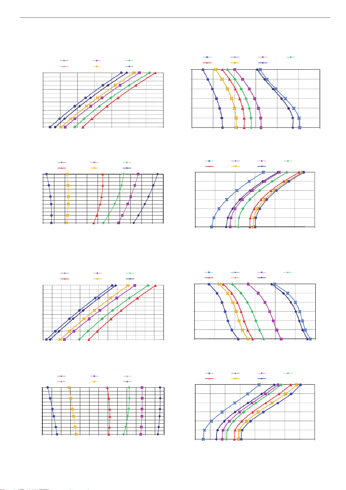
US FLOOR / FLOOR Minichiller inverter Duo
US 12 E
18
17
16
[°C]
15
[°C]
14
13
12
11
10
9
8
7
Outlet wa te r temperature
Temperatura a cqua out
6
5
5,5
aria-air
45°C
aria-air
30°C
6,5
7,5
Capacità frigorifera
Cooling
aria-air
aria-air
8,5
capacity[kW]
40°C
25°C
9,5
[kW]
aria-air
35°C
aria-air
20°C
10,5
11,5 12,5
55
[°C]
50
[°C]
45
40
35
30
Temperatura acqua out
Outlet water temperature
25
8 9 10 11 12 13 14
aria-air
aria-air
12°C
-7°C
Capacità termica [kW]
Heating capacity [kW]
aria-air
aria-air
7°C
-10°C
aria-air
aria-air
2°C
-15°C
aria-air
-2°C
aria-air
2,5
aria-air
12°C
-7°C
aria-air
45°C
aria-air
30°C
18
17
[°C]
16
[°C]
15
14
13
12
11
10
9
8
7
6
Temperatura a cqua out
Outlet water temperature
5
1,4 1,6 1,8 2,0 2,2 2,4 2,6 2,8 3,0 3,2 3,4 3,6
Potenza ass orbita
Power input
in
cooling
aria-air
40°C
aria-air
25°C
in
refrigerazione
[kW]
aria-air
aria-air
[kW]
35°C
20°C
55
[°C]
50
[°C]
45
40
35
30
Temperatura acqua out
Outlet water temperature
25
2,0
aria-air
aria-air
3,0
Potenza assorbita
Power input
in
7°C
-10°C
3,5
in
pompa
heating
[kW]
aria-air
aria-air
di
2°C
-15°C
4,0
calore
aria-air
-2°C
4,5
5,0
[kW]
US 16 E
[°C]
[°C]
Outlet water temperature
Temperatura acqua out
[°C]
out [°C]
Temperatura acqua
Outlet water temperature
aria-air
45°C
aria-air
30°C
18
17
16
15
14
13
12
11
10
9
8
7
6
5
7,5 8,0 8,5 9,0 9,5 10,0 10,5 11,0 11,5 12,0 12,5 13,0 13,5 14,
18
17
16
15
14
13
12
11
10
9
8
7
6
5
1,6 1,8 2, 0 2,2 2,4 2,6 2,8 3,0 3,2 3,4 3,6 3, 8 4,0 4,2
Capacità frigorifera
Cooling
aria-air
45°C
aria-air
30°C
Potenza assorbita
Power in put
aria-air
aria-air
capacity[kW]
aria-air
40°C
aria-air
25°C
in
refrigerazione
in
cooling
40°C
25°C
[kW]
[kW]
[kW]
aria-air
aria-air
aria-air
aria-air
35°C
20°C
35°C
20°C
aria-air
12°C
aria-air
-7°C
55
[°C]
50
out [°C]
45
40
35
30
Temperatura ac qua
Outlet wa ter temperature
25
0
9 10 11 12 13 14 15
aria-air
12°C
aria-air
-7°C
55
[°C]
50
[°C]
45
40
35
30
Outlet water temperature
Temperatura acqua out
25
2,5 3,0 3,5 4,0 4,5 5,0 5,5 6,0 6,5
aria-air
7°C
aria-air
-10°C
Capacità termica [kW]
Heating c apacity [kW]
aria-air
7°C
aria-air
-10°C
Potenza assorbita
Power input
in
in
heating
pompa
[kW]
aria-air
aria-air
aria-air
aria-air
di
2°C
-15°C
2°C
-15°C
calore
[kW]
aria-air
aria-air
-2°C
-2°C
42
Page 44
US FLOOR / FLOOR Minichiller inverter Duo
24 OPERATION LIMITS
24.1 Evaporator water flow rate
The nominal water flow rate is referred to a temperature differential of ∆T=5°C between inlet and outlet of the evaporator. The
allowed maximum flow rate is corresponding to ∆T=3°C; higher values may cause too high pressure drops. The allowed minimum
water flow rate is the one corresponding to ∆T=8°C (except for the model US 06 for which the maximum value of ∆T is 6,25°C.
Insufficient water flow may in fact cause too low evaporating temperatures with the intervention of safety devices for stoping the
operation of the unit and, in some particular cases, the water can freeze in the evaporator coil causing the refrigeration circuit to
break down or causes the increasing of the condensing pressure with the shutdown risk of the appliance and the compressor
could be damaged.
We enclosed below a most accurate table showing the minimum water flow that should be ensured for the plate heat exchanger
in order to have the proper operation of unit as a function of the model (note: the water flow switch is used for preventing the
freezing sensor from failure in the case of insufficient water flow but it does not ensure the minimum flow rate required in order
the unit can work properly).
Model
Cooling capacity for reference [kW] 5,14 8,33 11,69 13,15
Minimum water flow rate that to ensure [m3/h] 0,71 0,90 1,26 1,41
As a first approach, and in the absence of other detection systems, the proper water flow for getting the best performance from
your unit can be found at maximum speed of the circulator, using the pressure gauges for controlling the pressure difference
between the return and the delivery water on the outside water connections of the unit and make sure that such value is equal or
less than the available head pressure indicated on the curve shown in chapter 17 for the respective models and if it’s necessary
you change the settings (for the related circulator) that are reported in the manual cod. 9120523.xx.
24.2 Chilled water production (summer operation)
The allowed minimum temperature at the evaporator’s outlet is 5°C; for very lower temperatures, the unit should undergo some
necessaries structural modifications and different setting parameters of the controller with micro-processor. In this case contact
our company for the feasibility study and evaluation of changes to be made according to your requests. The maximum
temperature that can be maintained at the outlet of the evaporator is 25°C. In any case, the maximum electrical input occurs for
the heat pump operating mode at a water outlet temperature of 55°C and with outdoor temperature of -10°C.
24.3 Hot water production (winter operation)
Once the system is working at the right temperature, the inlet hot water temperature should not to be lower than 25°C; the
lowest values that are not related to transitional or start-up stages may cause incorrect working operation to the system with the
possible breakdown of the compressor. The maximum outlet water temperature should not exceed 58°C. At this temperature, the
power consumption and the performances in terms of C.O.P. are enhanced when the outdoor temperature is higher than 5°C,
even if the unit is still able to work up to the limit of -15°C.
For higher temperatures than those pointed out, especially if have a concomitant with the reduction of the water flow rate, it may
cause abnormalities to the normal operating of the unit, or the safety devices act in critical cases. The maximum power
consumption of the heat pump alone occurs during the operation with outlet water temperature of 58°C and outdoor
temperature of -15°C.
06 09 12 16
US
24.4 Ambient air temperature
The units are designed and manufactured to operate, in summer operation, with the condensate control, with outdoor air
temperatures ranging between -10°C and 46°C. While operating as a heat pump, the admitted outdoor air temperatures range
changes from -15°C to 40°C depending on the water outlet temperature as indicated in the below table.
Operation limits
Water chiller mode
Ambient temperature Minimum -10°C Maximum +46°C
Water outlet temperature Minimum +5°C Maximum +25°C
Heat pump mode
Ambient temperature Minimum -15°C Maximum +30°C
Water outlet temperature Minimum +25°C Maximum +58°C/+63°C*
Heat pump mode for sanitary hot water
Ambient temperature with maximum water temp. 48°C Minimum -15°C Maximum +40°C
Ambient temperature with maximum water temp. 55°C Minimum -15°C Maximum +35°C
Water outlet temperature Minimum +20°C Maximum +58°C/63°C
Herein below are reported the graphics operating limits during the air conditioning and domestic hot water production modes.
43
Page 45
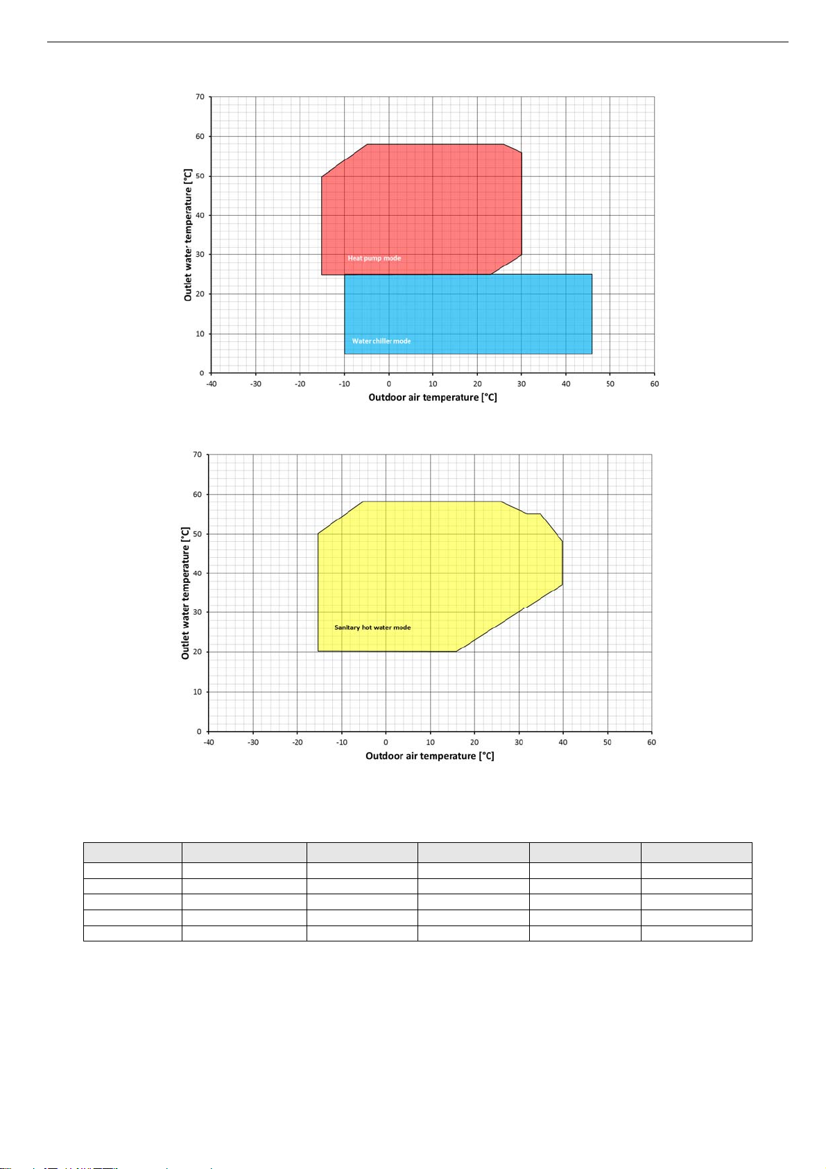
US FLOOR / FLOOR Minichiller inverter Duo
CHILLER/HEAT PUMP MODE
DOMESTIC HOT WATER MODE
25 CORRECTION FACTORS FOR OPERAZIONI WITH GLYCOL
The following correction factors are to be used only if the indoor unit is installed in any internal area of the building subject to low
temperatures and with the judgment of adding a certain quantity of glycol for protecting the hydraulic circuit.
Glycol % Freezing point (°C) CCF IPCF WFCF PDCF
10 -3,2 0,985 1 1,02 1,08
20 -7,8 0,98 0,99 1,05 1,12
30 -14,1 0,97 0,98 1,10 1,22
40 -22,3 0,965 0,97 1,14 1,25
50 -33,8 0,955 0,965 1,2 1,33
CCF: Capacity correction factor. IPCF: Input power correction factor.
WFCF: Water flow correction factor. PDCF: Pressure drops correction factor.
The water flow rate and pressure drop correction factors are to be applied directly to the values given for operation without
glycol. The water flow rate correction factor is calculated in order to get the same temperature’s difference that would be
obtained without glycol. The pressure drop’s correction factor takes into account the different water flow rate obtained from the
application of the water flow rate correction factor.
44
Page 46
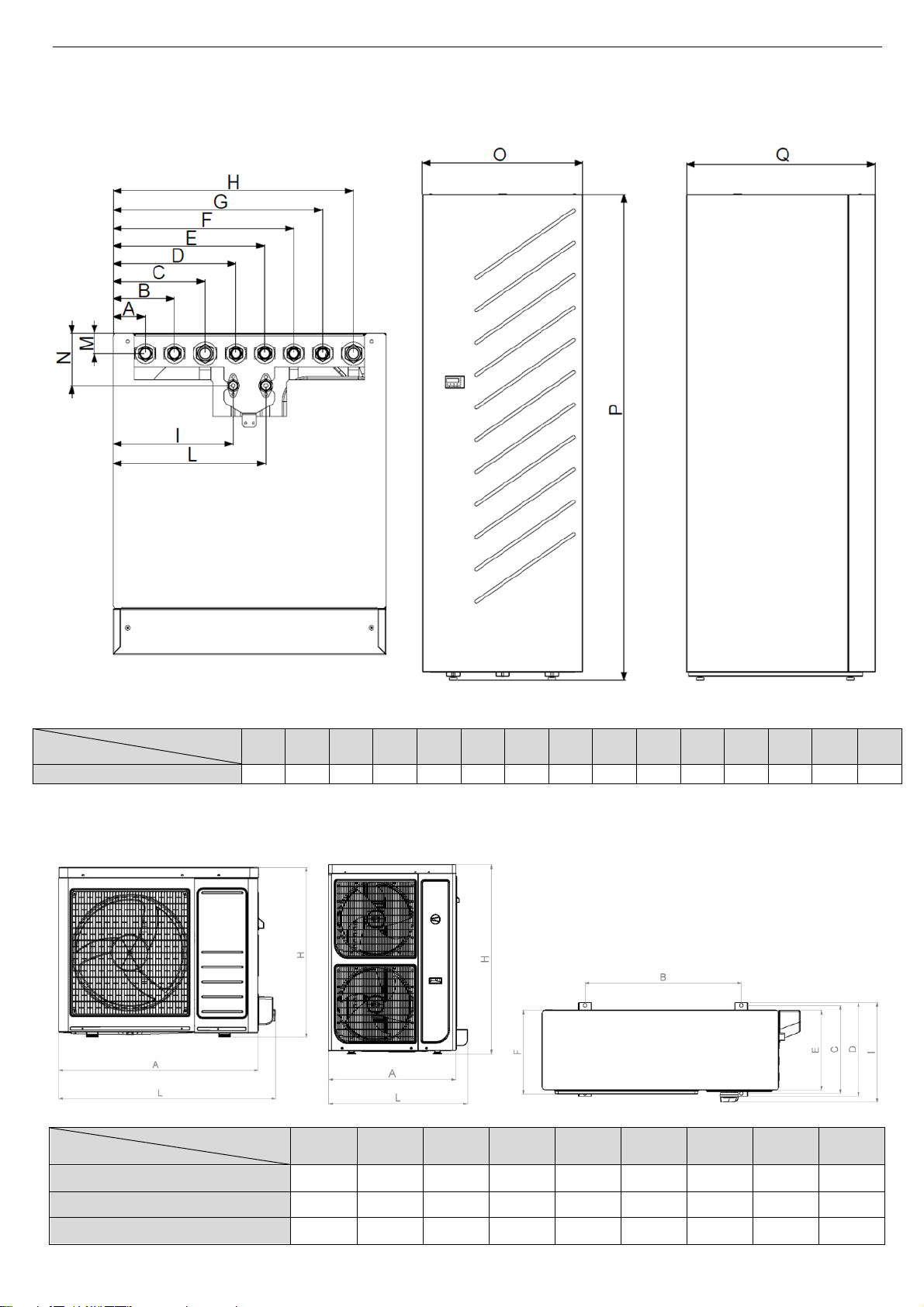
26 DIMENSIONS
0
S
26.1 INDOOR UNITS
US FLOOR / FLOOR Minichiller inverter Duo
DIMENSIONS (mm)
MODEL
06-09-12-16 71 134 201 268 331 394 457 524 262 333 44 114 595 1789 70
26.2 OUTDOOR UNITS
US 06 - 09
MODELS
US 06 E
US 09 E
US 12 E – US 16 E
IZE (mm)
A B C D E F G H I L M N O P Q
US 12 - 16
A B C D E F H I L
844 560 330 360 313 329 719 379 916
895 590 333 355 304 319 861 374 975
940 633 404 448 370 392 1402 454 1024
45
Page 47
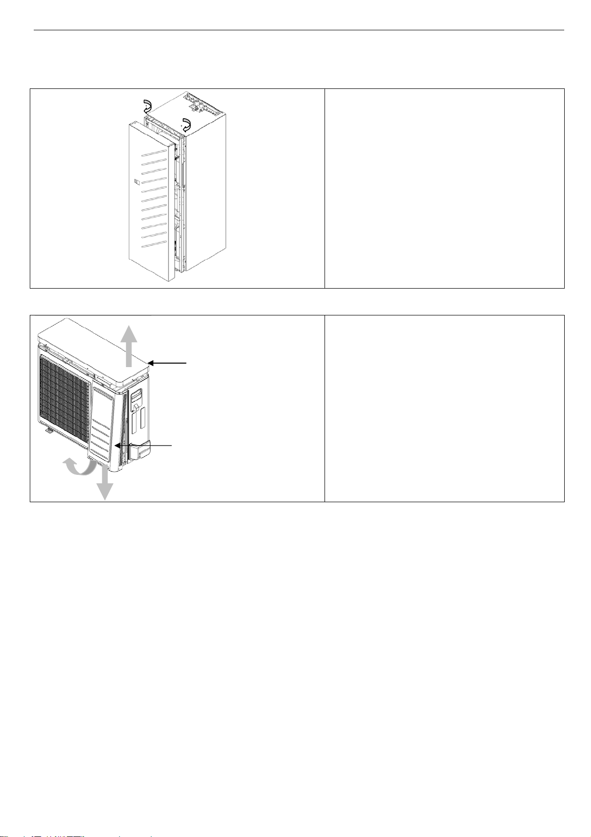
US FLOOR / FLOOR Minichiller inverter Duo
27 ACCESS PROCEDURE TO INTERNAL PARTS
27.1 INDOOR UNIT
27.2 OUTDOOR UNIT
1) Remove the two screws on the top of the unit.
2) To remove the front panel, it is sufficient to lift it and
then to pull it in front side, while during the
repositioning period, you should insert the rivets located
in the sides of the front panel into the holes on the
edges on the right side and left side panels, then slide
the panel down.
5)
4)
2)
Top panel
Front –right side panel
1) Remove the mounting screws connecting the top
panel of the unit
2) Remove the top panel
3) Remove the mounting screws connecting front-right
side panel.
4) Push down on the front-right side panel
5) Remove the front right side panel by tilting it in the
indicated direction.
46
Page 48
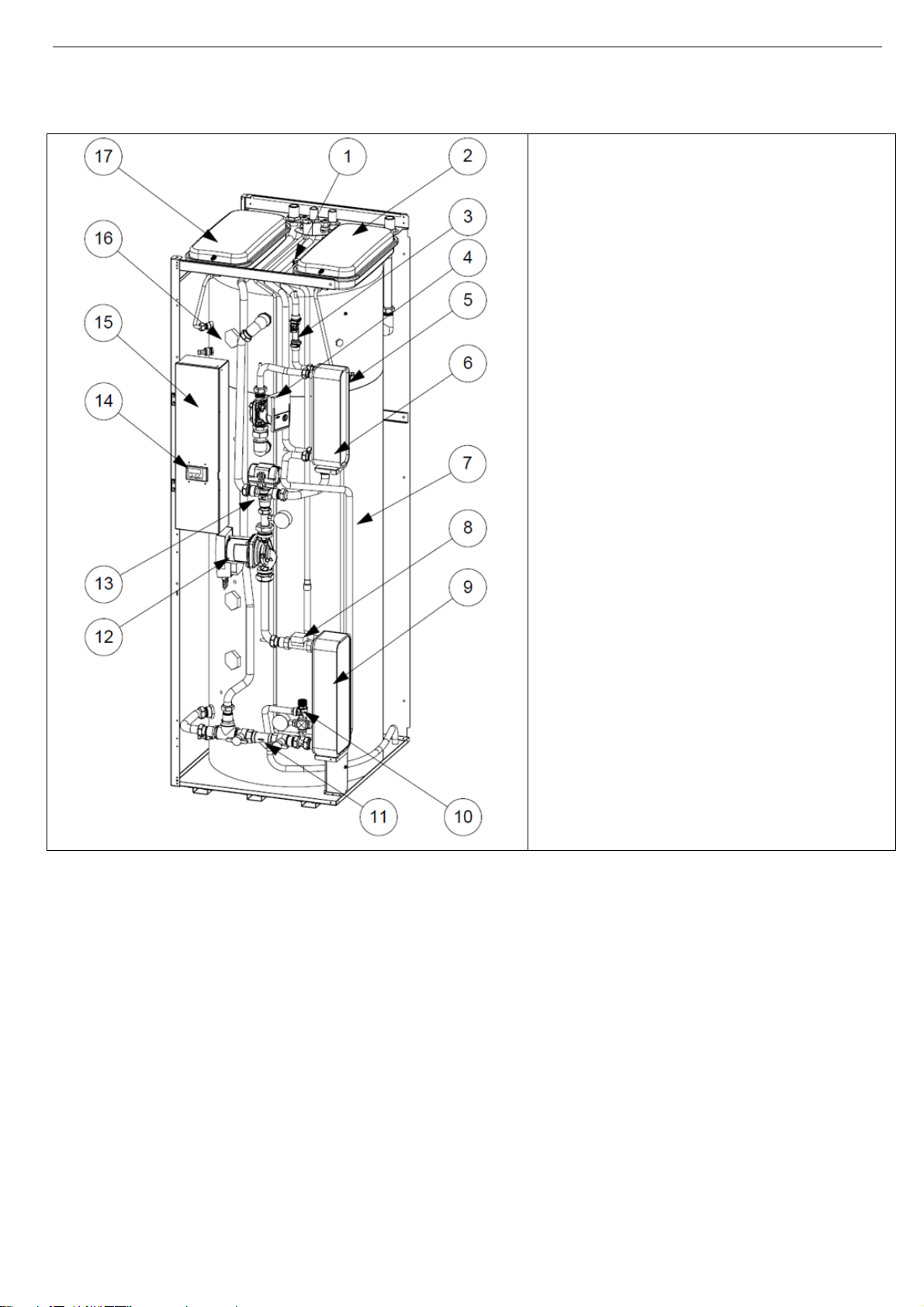
28 COMPONENTS OF INDOOR AND OUTDOOR UNITS
28.1 Indoor unit model: FLOOR/FLOOR-S
US FLOOR / FLOOR Minichiller inverter Duo
MODEL FLOOR
1) Automatic air vent valve for DHW technical side
2) Expansion vessel for DHW technical side
3) Flowmeter DHW - R
4) Circulator DHW - R
5) Automatic air vent for plant side
6) Plate heat exchanger DHW – R
7) Technical puffer tank for DHW (190 L)
8) Safety pressure switch
9) Plate heat exchanger
10) 3 bar relief valve
11) Y filter
12) Circulator
13) Plant side/DHW technical side reverse valve
14) User’s interface
15) Electric panel
16) Technical puffer tank for plant side (40 L)
17) Expansion vessel for plant side
47
Page 49
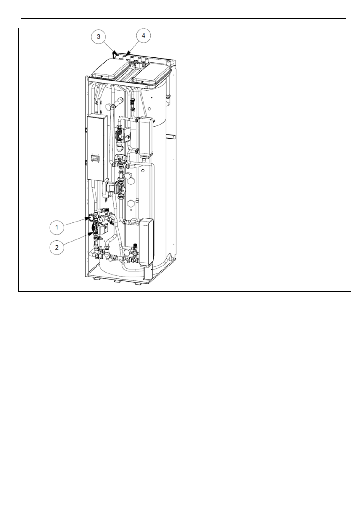
US FLOOR / FLOOR Minichiller inverter Duo
MODEL FLOOR-S
1) Solar group
2) Solar side circulator
3) Solar plant outlet pipe (label "to the solar plant")
4) Solar plant return pipe (label “from the solar
plant”)
48
Page 50
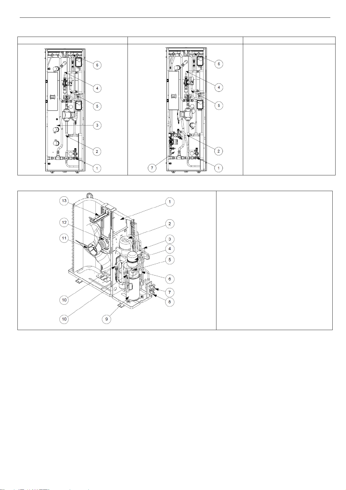
28.2 Indoor unit temperature sensors
US FLOOR / FLOOR Minichiller inverter Duo
Model FLOOR Model FLOOR-S
28.3 OUTDOOR UNIT
Position of temperature sensor
1) Heat exchanger inlet
2) Heat exchanger outlet
3) DHW technical side
4) DHW-R primary circuit inlet
5) DHW-R secondary circuit
inlet
6) DHW-R secondary outlet
7) Solar coil
1. Condenser coil assy
2. Liquid separator
3. 4-way valve
4. Liquid receiver
5. High pressure flow switch
6. Electronic expansion valve
7. Gas valve
8. Liquid valve
9. Compressor
10. Transducers
11. Fan
12. Fan motor
13. Fan motor support
Note: The figure is referring to the outdoor
unit with model name US 09 and is included
for illustration purposes. The outdoor units US
12 and US 16 have two fans.
49
Page 51
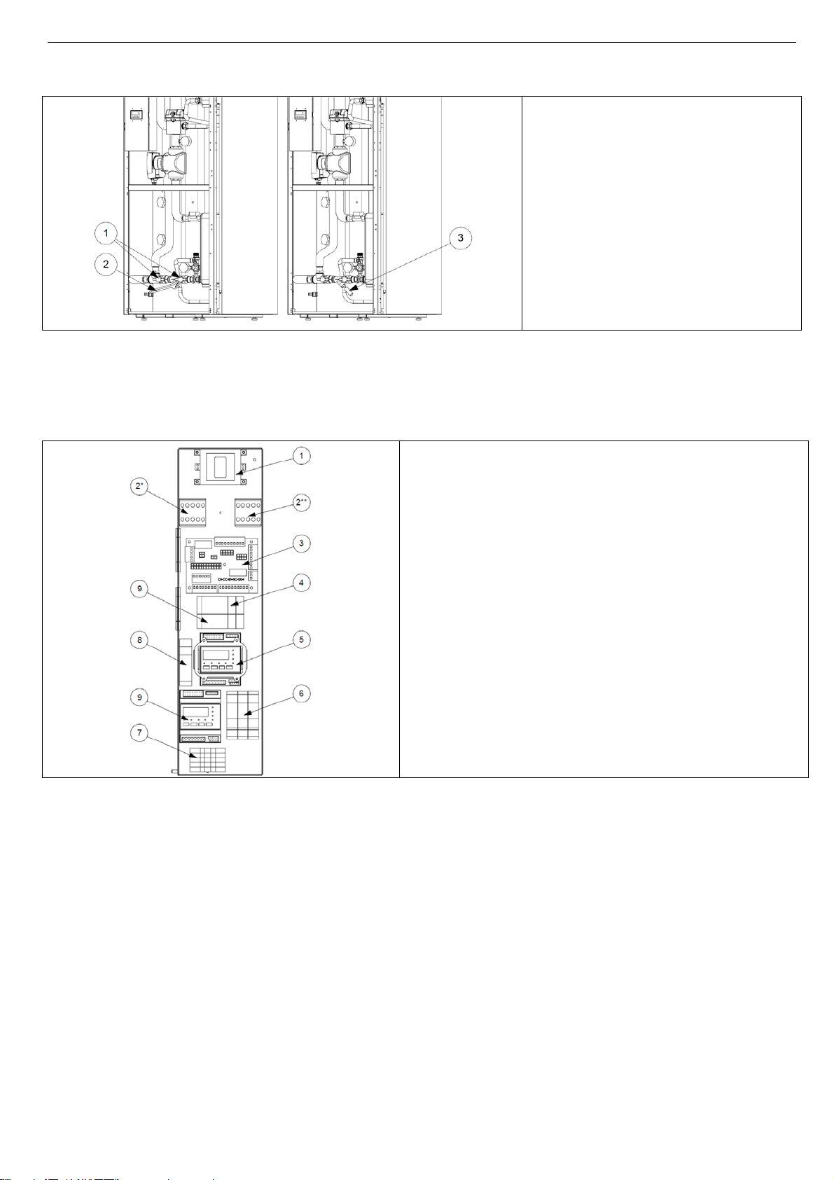
US FLOOR / FLOOR Minichiller inverter Duo
29 FILTER CLEANING
30 WIRING DIAGRAMS
30.1 INDOOR UNIT ELECTRIC PANEL LAYOUT
1) Close the taps (1)
2) Remove the Y-filter plug (2) with a
socket wrench of 27
3) Remove the metallic mesh filter
cartridges (3) and wash it under
running water brushing it carefully
4) Place the metallic mesh filter cartridges
in its position
5) Screw the plug filter
6) Open the taps (1)
1) Electric transformor 240V-12V-30VA_[TF]
2) 4 pole contactor 240v coil 230V 20A_[KM1*-KM2**]
3) Support board_[AB]
4) Auxiliary power supply terminal block_[M4]
5) User interface_[CB]
6) Fuses for electric heaters protection_[F1-F2-F3-M2]
(only in case of electric heater kit installation)
7) Power supply terminal block_[M1]
8) Auxiliary power supply terminal block_[M3]
9) Expansion board terminal block for the module GI2_[M5-
ECB] (present only the optional GI2 module)
* Present only with the optional electric heater RExxxx kit (only in
case of technical side electric heater DHW)
** Present only with the optional electric heater RExxxx kit
(only in case of plant side electric heater)
50
Page 52
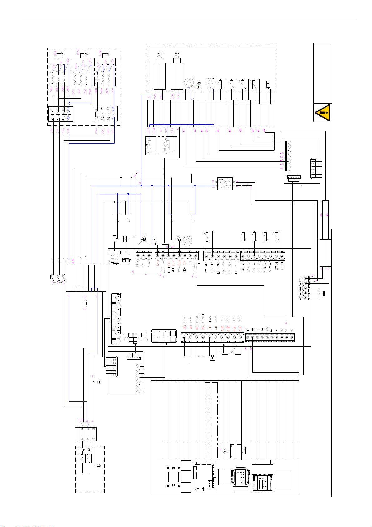
30.2 SINGLE-PHASE INDOOR UNIT
US FLOOR / FLOOR Minichiller inverter Duo
(1) R1-ACS
(1)K1
(1) R2-ACS
n°=2
(2) R-GI
Thermostat forAC S
TH_[IN]
TH_[A1]
(1) Termostati ACS /
(2)K2
M4_[A21]
M4_[A11]
n°=3
n°=3
GI - Circolatore
Circulator
ACS - Circolatore
Valvola 3 vie doppio set-point
3-way valve double set
Abilitazione caldaia
Circulator
Enabling boiler
TH_[IN]
TH_[A1]
(2) Termostati GI /Thermostat forGI
M4_[TGI]
M4_[A12]
M4_[A22]
M4_[TACS]
Bianco/ White
Grigio/ Grey
n°=2
ACS - Valvola 3 vie SAN
Mixing valve
Solar Circulator
#K- Circolatore solare
#K- Valvola Miscelatrice
M5_[KCS]
M5_[ K-N]
M5_[KMO]
M5_[KMC]
n°=2
ACS - Ricircolo
Recirculation
3-way valve SAN
Mixing probe
Circulator recovery
#K-Sonda Miscelatrice
#K- Circolatore di rilancio
-t°
M5_[K1]
M5_[KDO]
M5_[KDON]
M5_[K1]
TF
ACS - Acqua sanitaria
Sanitary water
-t°
Solar tank sensor
Solar collector senso
#K- Sonda accumulo solare
#K-Sonda collettore solare
-t°
-t°
M5_[KS1]
M5_[KS1]
M5_[KS2]
M5_[KS2]
F12
#K- Sonda accumulo
Tank sensor
-t°
Thermostat
#K- Sonda ricircolo
Recirculation sensor
#Termostato Ambiente
-t°
M5_[K2]
M5_[K2]
M5_[KPWM]
M5_[KPWM]
8
7
6
CN1
5
4
3
2
1
GI - Sonda uscita H20
output sensor
GI - Remota Impia nto
GI - Sonda Ingresso H 20
Input sensor
-t°
remote plant
-t°
-t°
ATTENZIONE
ne ha provocato l'interruzione.
Non sostituire i fusibili con altri di amperaggio superiore: potreste
danneggiare il componente o il circuito che si intendeva proteggere.
Non sostituire un fusibile interrotto senza aver prima trovato la causa c he
M1
#ECB
CN3
CN2
[pin24]
[pin24]
Brown
Marrone
n°=2
n°=3
n°=2
n°=2
n°=2
n°=2
CN5
F 1-2-3
M3_ [LC]
M2_ [N-3]
M1
QD
M4_ [N-2]
M4_ [N-1]
M3_ [LA]
M3_ [LB]
FL1
[L1]
L
M3_ [PE]
[N]
[PE]
N
PE
230Vac
50Hz
1Ph-N-PE
CN4
PWM2 0÷10V
CN14
PWM2 0÷10V
CN10
CN3
CN8
AB
CN9
CN6
CN2
CN2
CN3
1
2
3
CB
4
5
6
7
8
CN1
CN1
-t°
-t°
ACS
Flow
Remote on/off
Double set-point
GI - On-off re moto
GI - Doppio set-point
Description
Descrizione
Scheda d'appoggio / Aux board
Controllo principale / Control board
Morsettiera Ausiliari / Termi nal Aux
Morsettiera GI2 / Expansion Terminal GI2
Morsettiera alimentazione / Power terminal
Morsettiera Neutro Resistenza / Neutral terminal for Resistor
Morsettiera alimentazi one ausiliaria / Au x Power supply Terminal
NOTES Read before installation
M1
Component
Componente
NOTE da leggere prima dell'installazione
Position in the control cabinet
Posizione nel quadro elettrico
AB
M2
M4
M3
CB
#M5
KM2
TF
KM1
GI - Flussostato
Opzionale / Optional
Contattore resistenza ACS / Contactor Resistance ACS
Controllo Espansione GI2 / Expansion con trol board GI2
Contattore resistenza Impianto / Contactor Resi stance System
Non installato nel quadro el ettrico / Not installed in the control cabinet
#ECB
(1)KM1
(2)KM2
10
14
CN
CN
CN12
AB
CN3
CN
7
CN8 CN9
output primary
input secondary
Ingresso secondario
ACS - Mandata primario
Numero filo / Number of wire
Punto di massa / Ground point
Morsetto a vite / Screw terminal
Morsetto a molla / Spring terminal
M4
M5
CB
M3
CN12
kW]
Fuse 5x20 T, 5A, 250V
Sonda / Probe NTC 10K @ 25°C
Interruttore di dispersion e verso terra/ Earth leakag e circuit breaker
-t°
*QD
Fusibile /
Gruppo idronico / Hydronic group
Fusibile / Fuse 5x20 T, 10A, 250V
cqua Calda Sanitaria / Domestic Hot Water
A
Fusibile seziona bile / Fu se 1 0.3x38, 16A, 500V
GI
FL1
F12
ACS
F 1-2-3
M2
F
1-2-3
#ECB
[1.5kW / 3kW / 4.5
[1.5kW / 3kW / 4.5 kW]
Resistenza GI / GI Heating Resistance
Resistenza ACS / ACS Heating Resistan ce
Trasformatore/ Tran sformer 230Vac-12Vac
Termostato manuale di sicurezza / Manual Thermostat safety
Termostato automatico di sicurezza / Automatic Thermostat safety
TF
(1)
2)R-GI
(
(1)/(2) TH1
(1)/(2) TH2
R1-ACS R2-ACS
M1
M4_ [12V]
M4_ [12V]
Flowmeter
+5V
CN7
ACS - Flussimetro
# Opzione espansione GI2 /Optional expantion GI2
* Da reperire in loco /Obtain locally
(1) Opzione Resistenza [ACS] /Options Heating resistor [ACS]
(2) Opzione Resistenza Impianto /Option s Heating resistor system
La legenda riporta simboli non necessariamente presenti nel seguente schema elettrico /The legend shows symbols not necessarily present in the circuit diagram
51
Page 53
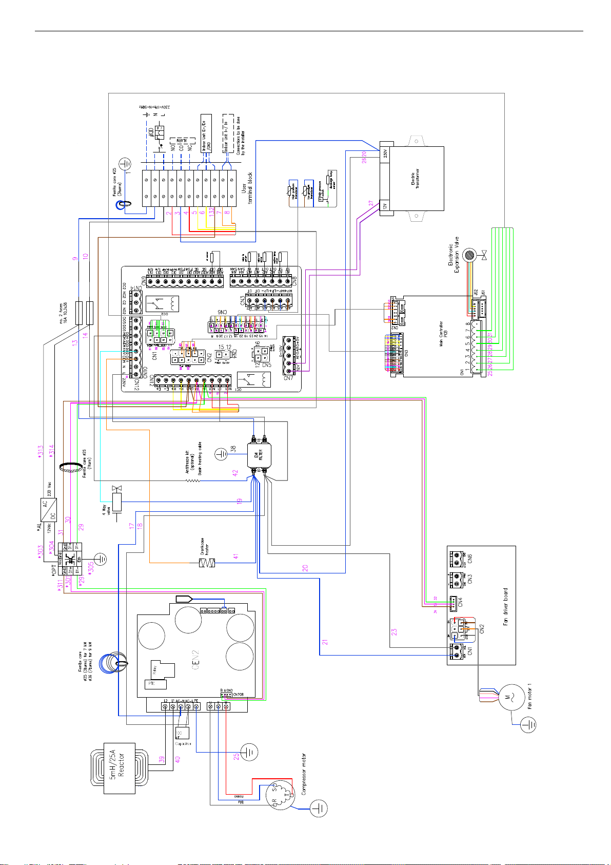
US FLOOR / FLOOR Minichiller inverter Duo
30.3 OUTDOOR UNITS
30.3.1 Mod. US 06 - 09
R- NC N NO L1 N1 GND
I-I-I+
GNDR
R+
L1 N 1
GND
R-
I+
R+
NC N NO
GNDR
Present for quick managementDH W
(*) Presente conl a gesti one rapida dell'ACS /
(#) Da reperire in loco / Ob tai nl ocally
elettrico / The legend shows symbols not necessarilypresent in the circuit diagram
La legenda riporta simboli non necessariamente presenti nel seguente schema
Heat Sink
Temp Sensor
52
Page 54
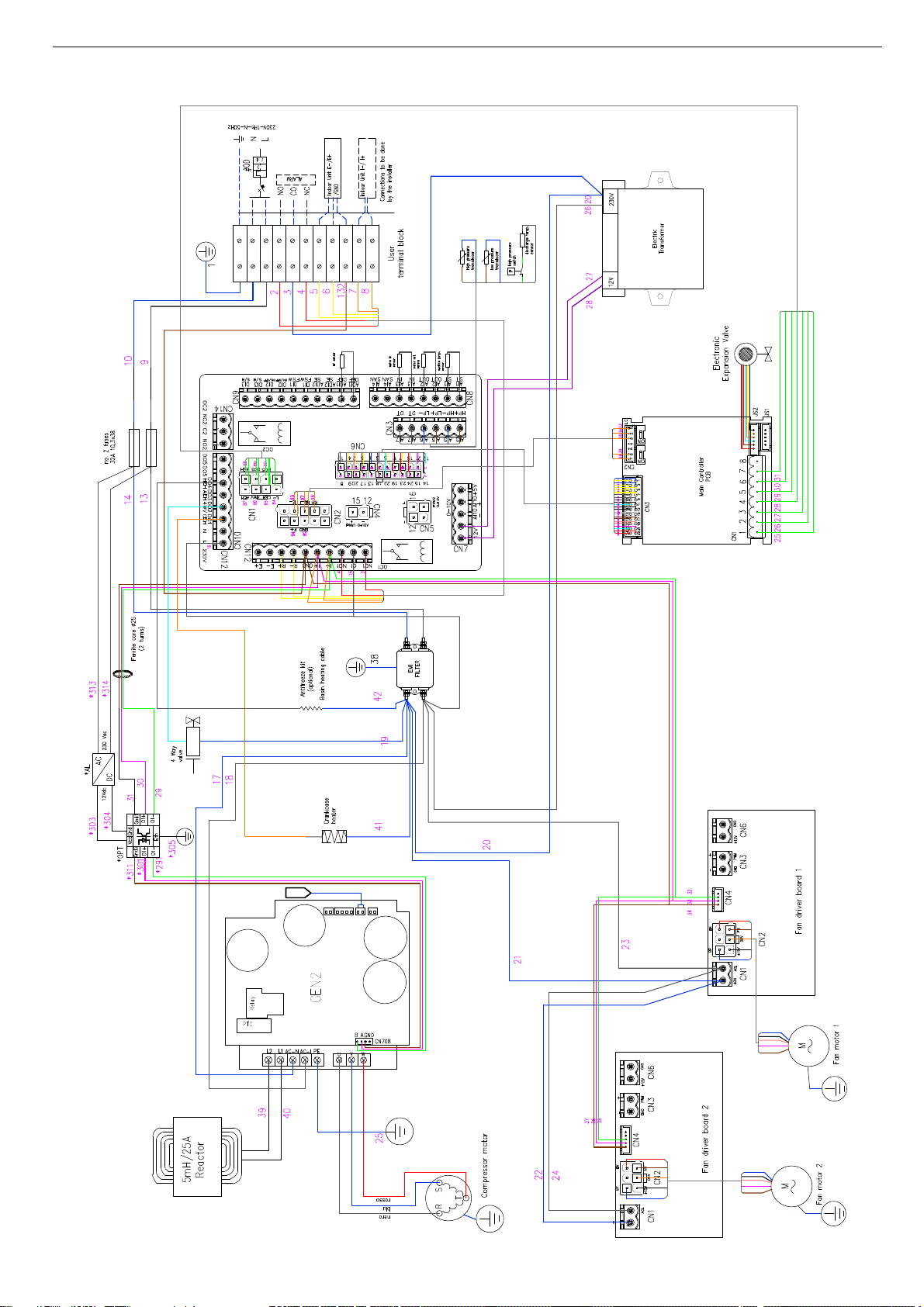
30.3.2 Mod. US 12
US FLOOR / FLOOR Minichiller inverter Duo
GNDR
R- NC N NO L 1 N1 GND
R+
R+
I-I-I+
R- NC N NO L1 N1 GND
I+
GNDR
(*) Presente conl ag estione rapida dell'ACS / Present for quick managementD HW
(#) Da reperire in loco / Obtai nl ocally
La legenda riporta simboli non necessariamente presenti nel seguente schema
elettrico / The legend shows symbols not necessarily presenti n thecircuit diagram
53
Heat Sink
Temp Sensor
Page 55
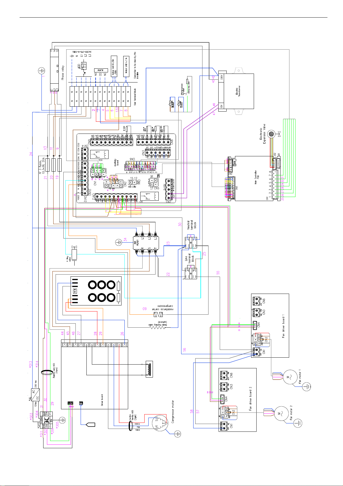
US FLOOR / FLOOR Minichiller inverter Duo
30.3.3 Mod. US 16
GND
N
L1
GND
N
NO1 N NC1
R- L3 L 2
R+
GNDR
NC1
NO1 N
R- L3 L2 L 1
R+
I+
GNDR
I-I-I+
Present for quick managementD HW
(*) Presente con la gestionerapi da dell'ACS /
(#) Da reperire in loco / Obtai nl ocally
La legenda riporta simboli non necessariamente presenti nel seguente schema
elettrico / The legend shows symbols not necessarily present in theci rcuitdiag ram
R S T
DC2-
DC1-
DC-
DC2+
DC1+
DC+
DC-
L1 L2 DC+ NWVUP
Reactor
CN607
CN604
V
U
W
Heat Sink
Temp Sensor
54
Page 56

US FLOOR / FLOOR Minichiller inverter Duo
31 LIMITATION OF WARRANTY
This guarantee does not cover breakdowns due to:
• damages caused by impacts or accidents during transportation and handling or inappropriate use of the unit
• the unit is installed in unsuitable environment and not respecting the minimum conditions of required space
• the unit is suitable for outdoor installed
• water filter not installed on water charge/topping-up pipe
• safety valve and expansion vessel not installed on water charge/topping-up line (and on solar circuit if present)
• manumission of the safety flow switch of the indoor unit
• power supply with frequency or voltage spikes that don’t comply with nominal characteristics of the machine
• improper maintenance and failed replacement of anode
• faulty electrical connections, improper grounding, manufacturer’s wiring diagrams not respected
• abnormal calcium deposits on hydraulic safety devices or on inner accessories
• modification of the equipment of the unit without the approval of manufacturer or use of spare parts not approved.
55
Page 57

Page 58

Page 59

Page 60

bit.ly/rdzwebsite
12/2016
9120488.02
 Loading...