

Page 1

Air Handling Units
Unità Trattamento Aria
Unit Comfort UC 300-M
50 Hz Model / Modello 50 Hz
60 Hz Model / Modello 60 Hz
Residential Dehumidifier with VMC System
Deumidificatore Residenziale con Sistema VMC
TECHNICAL / INSTALLATION MANUAL
MANUALE TECNICO / INSTALLAZIONE
Page 2

Page 3

SAFETY WARNINGS
AVVERTENZE PER LA SICUREZZA
Read this manual carefully before installing and/or using the
equipment and keep it in an accessible place.
This equipment constitutes a component which is part of
complex installations: it is the responsibility of the electrical
installer to draw up the general diagram of the system and
the electrical connections outside the equipment.
The manufacturer’s technical oce can be contacted on the
numbers shown on the back of this manual for queries or
special technical requests.
•
• It is essential to connect the equipment to an eective earthing
• Before making the electrical connection, ensure that the voltage
• Before performing any intervention on the unit, ensure that the
• Do not alter or tamper with the safety devices.
• Do not direct jets of water onto the electrical parts or onto the
• This appliance is not suitable for use in explosive or potentially
• During installation or when it is necessary to intervene on the
• The pressure of the refrigerating circuit and the electrical
CAUTION
Installation and maintenance must only be carried out by
qualied personnel.
The hydraulic and electrical systems and the places where
the equipment is to be installed must comply with the safety,
accident prevention and re prevention standards in force
in the country of use.
system and include it in an equipotential system whose
eectiveness.
and frequency shown on the data plate correspond to those of
the power supply system.
electrical power supply has been disconnected.
equipment packaging.
explosive atmospheres.
equipment, it is necessary to follow the rules shown in this manual
very carefully, respect the information on board the unit and
alwayss take all the appropriate precautions.
components may create dangerous situations during installation
and maintenance interventions.
Leggere con attenzione questo libretto prima
dell’installazione e/o dell’uso dell’apparecchiatura e
conservarlo in un luogo accessibile.
La presente apparecchiatura costituisce un componente che
fa parte di installazioni complesse: è compito dell’impiantista
elettrico redigere lo schema generale dell’impianto e dei
collegamenti elettrici esterni all’apparecchiatura.
L’ufficio tecnico del Costruttore si rende disponibile
ai numeri indicati sul retro del presente libretto per
consulenze o richieste tecniche particolari.
•
• E’ indispensabile collegare l’apparecchiatura ad un ecace
• Prima di eseguire il collegamento elettrico, accertarsi che la
• Prima di eettuare qualsiasi intervento sull’unità, assicurarsi
• Non alterare o manomettere i dispositivi di sicurezza.
• Non dirigere spruzzi d’acqua sulle parti elettriche o
• Questo apparecchio è inadatto all’utilizzo in atmosfere
• All’atto dell’installazione o quando si debba intervenire
• Le pressioni presenti nel circuito frigorifero ed i componenti
ATTENZIONE
L’installazione e la manutenzione vanno eseguiti solo da
personale qualicato.
Gli impianti idraulici, elettrici ed i locali di installazione
delle apparecchiature devono rispondere alle norme di
sicurezza, antinfortunistiche e antincendio in vigore nel
Paese di utilizzo.
impianto di terra e includerla in un sistema equipotenziale la
cui ecacia deve ottemperare alle norme in vigore.
tensione e la frequenza riportate sulla targhetta caratteristiche
corrispondano a quelle dell’impianto d’alimentazione.
di aver tolto l’alimentazione elettrica.
sull’involucro dell’apparecchio.
esplosive o potenzialmente esplosive.
sull’apparecchiatura, è necessario attenersi scrupolosamente
alle norme riportate su questo manuale, osservare le
indicazioni a bordo unità e comunque applicare tutte le
precauzioni del caso.
elettrici presenti possono creare situazioni rischiose durante
gli interventi di installazione e manutenzione.
i - INFO
GENERAL WARNINGS
• This unit is used to control room humidity in summer
in combination with radiant cooling systems. Use is
recommended within the operation limits in residential
applications and/or commercial ones (e.g. offices). Any
other dierent use MUST be agreed in advance with RDZ
technical department.
• If, after having unpacked the equipment, any anomaly is noted,
do not use the equipment and contact an Assistance Centre
authorised by the manufacturer.
• After installation, dispose of the packaging in accordance with
the provisions of the regulations in force in the country of use.
• Use original spare parts only: disregarding this rule invalidates
the warranty.
AVVERTENZE GENERALI
• Questa macchina è prevista per il controllo estivo
dell’umidità ambiente in abbinamento con impianti di
rarescamento radiante. Il suo utilizzo è raccomandato,
entro i limiti di funzionamento, in ambienti civili e/o del
settore terziario (uci, ...), per climatizzazione nalizzata
al comfort ambientale. Ogni altra applicazione diversa
DEVE essere preventivamente concordata con l’Ucio
tecnico RDZ.
• Se dopo aver disimballato l’apparecchiatura si nota una
qualsiasi anomalia non utilizzare l’apparecchiatura e rivolgersi
ad un Centro di Assistenza autorizzato dal Costruttore.
• Alla ne dell’installazione smaltire gli imballi secondo quanto
previsto dalle normative in vigore nel Paese di utilizzo.
• Esigere solo ricambi originali: la mancata osservazione di
questa norma fa decadere la garanzia.
3
Page 4

• The manufacturer declines all responsibility and considers the
warranty invalid in the following cases:
- The aforementioned warnings and safety regulations, including
those in force in the country of installation, are not respected.
- The information given in this manual is disregarded.
- There is damage or injury to people, animals or objects, resulting
from incorrect installation and/or improper use of the products
and equipment..
- Inaccuracies or printing and transcription errors are contained
in this manual.
• The manufacturer also reserves the right to cease production at
any time and to make all the modications which it considers
useful or necessary without any obligation to give notice.
• Il Costruttore declina ogni responsabilità e non ritiene valida
la garanzia nei casi seguenti:
- Non vengano rispettate le avvertenze e le norme di
sicurezza sopra indicate, comprese quelle vigenti nei paesi
di installazione.
- Mancata osservanza delle indicazioni segnalate nel presente
manuale.
- Danni a persone, animali o cose, derivanti da una errata
installazione e/o uso improprio di prodotti e attrezzature.
- Inesattezze o errori di stampa e trascrizione contenuti nel
presente manuale.
• Il Costruttore, inoltre, si riserva il diritto di cessare la produzione
in qualsiasi momento e di apportare tutte le modiche che
riterrà utili o necessarie senza obbligo di preavviso.
DISPOSAL
In accordance with the provisions of the following
European directives 2011/65/EU, 2012/19/EU and
2003/108/EC, regarding reducing the use of
hazardous substances in electrical and electronic
equipment, in addition to waste disposal.
The crossed-out rubbish bin symbol shown on the equipment
indicates that, at the end of its useful life, the product must be
collected separately from other waste.
At the end of the life cycle of the unit, before its removal, the
following precautions must be taken:
The refrigerating gas contained within it must be recovered
separately by specialised personnel and sent to collection centres;
The lubrication oil for the compressors must also be recovered and
sent to collection centres;
The structure and the various components, if they can no longer
be used, must be demolished and divided up according to the
type of product: this is particularly important for the copper and
aluminium components, which are included in the machine in
moderate quantities.
All this helps collection, disposal and recycling centres reduce the
environmental impact this operation requires.
Appropriate separate waste collection for subsequent sending of
the disused equipment for recycling, treatment and compatible
environmental disposal contributes to preventing possible
negative eects on the environment and favours recycling of the
materials of which the equipment is composed.
The abusive disposal of the product by the user leads to the
application of the penalties envisaged by current regulations
regarding the matter.
SMALTIMENTO
In base a quanto previsto dalle seguenti direttive
europee 2011/65/UE, 2012/19/UE e 2003/108/
CE, relative alla riduzione dell’uso di sostanze
pericolose nelle apparecchiature elettriche ed
elettroniche, nonché allo smaltimento dei riuti.
Il simbolo del cassonetto barrato riportato sull’apparecchiatura
indica che il prodotto alla ne della propria vita utile deve essere
raccolto separatamente dagli altri riuti.
Al termine del ciclo di vita dell’unità, in previsione di una sua
rimozione, andranno seguiti una serie di accorgimenti:
Il gas refrigerante in essa contenuto va recuperato da parte di
personale specializzato ed inviato ai centri di raccolta;
L’olio di lubricazione dei compressori va anch’esso recuperato
ed inviato ai centri di raccolta;
La struttura ed i vari componenti, se inutilizzabili, vanno
demoliti e suddivisi a seconda del loro genere merceologico: ciò
vale in particolare per il rame e l’alluminio presenti in discreta
quantità nella macchina.
Tutto ciò per agevolare i centri di raccolta, smaltimento e
riciclaggio e per ridurre al minimo l’impatto ambientale che
tale operazione richiede.
L’adeguata raccolta differenziata per l’avvio successivo
dell’apparecchiatura dismessa al riciclaggio, al trattamento e allo
smaltimento ambientale compatibile contribuisce ad evitare
possibili eetti negativi sull’ambiente e sulla salute e favorisce
il riciclo dei materiali di cui è composta l’apparecchiatura.
Lo smaltimento abusivo del prodotto da parte dell’utente
comporta l’applicazione delle sanzioni previste dalla vigente
normativa in materia.
4
Page 5
INDEX INDICE
Description Descrizione Pag.
SAFETY WARNINGS AVVERTENZE PER LA SICUREZZA 3
GENERAL WARNINGS AVVERTENZE GENERALI 3
DISPOSAL SMALTIMENTO 4
PRELIMINARY OPERATIONS OPERAZIONI PRELIMINARI 6
DESCRIPTION OF THE EQUIPMENT DESCRIZIONE APPARECCHIATURA 7
Unit circuit description Descrizione circuiti macchina 8
Components description Descrizione componenti 8
Safety checks Controlli di sicurezza 9
INSTALLATION INSTALLAZIONE 10
1 - Positioning and xing to the ceiling 1 - Posizionamento e ssaggio a sotto 10
2 - Hydraulic connections 2 - Collegamenti idraulici 12
3 - Electrical connections 3 - Collegamenti elettrici 15
4 - Connection to the control units 4 - Collegamento alle centraline di comando 17
5 - Aeraulic connections 5 - Collegamenti aeraulici 19
6 - Free-cooling conguration 6 - Congurazione free-cooling 20
7 - Optional dumper installation 7 - Installazione serrande opzionali 22
START-UP AND TESTING AVVIAMENTO E COLLAUDO 23
1 - Hydraulic circuit adjusting 1 - Taratura circuito idraulico 23
2 - Unit starting 2 - Accensione macchina 25
3 - Parameters setting 3 - Settaggio parametri 26
FUNCTIONING FUNZIONAMENTO 27
1 - Overview 1 - Panoramica 27
2 - Flow rate diagram 2 - Schemi graci gestione portate aria 30
3 - Components diagram 3 - Schemi graci gestione componenti 32
MAINTENANCE MANUTENZIONE 34
1 - Regular maintenance 1 - Manutenzione ordinaria 34
2 - Extraordinary maintenance 2 - Manutenzione straordinaria 36
TECHNICAL DATA AND PERFORMANCE DATI TECNICI E PRESTAZIONI 38
1 - Dimensions 1 - Dimensioni 38
2 - Technical data 2 - Dati tecnici 38
3 - Operating limits 3 - Limiti di funzionamento 39
4 - Operation in ventilation only 4 - Funzionamento in sola ventilazione 40
5 - Summer performance 5 - Prestazioni estive 40
6 - Operation in winter integration mode 6 - Funzionamento integrazione invernale 45
7 - Recovery unit performance 7 - Prestazioni recuperatore 48
8 - Fan performance 8 - Prestazioni ventilatori 52
9 - Acoustic characteristics 9 - Caratteristiche acustiche 55
10 - Pressure loss of the hydraulic circuit 10 - Perdita di carico circuito idraulico 55
WIRING DIAGRAMS SCHEMI ELETTRICI 56
i - INFO
5
Page 6
PRELIMINARY OPERATIONS OPERAZIONI PRELIMINARI
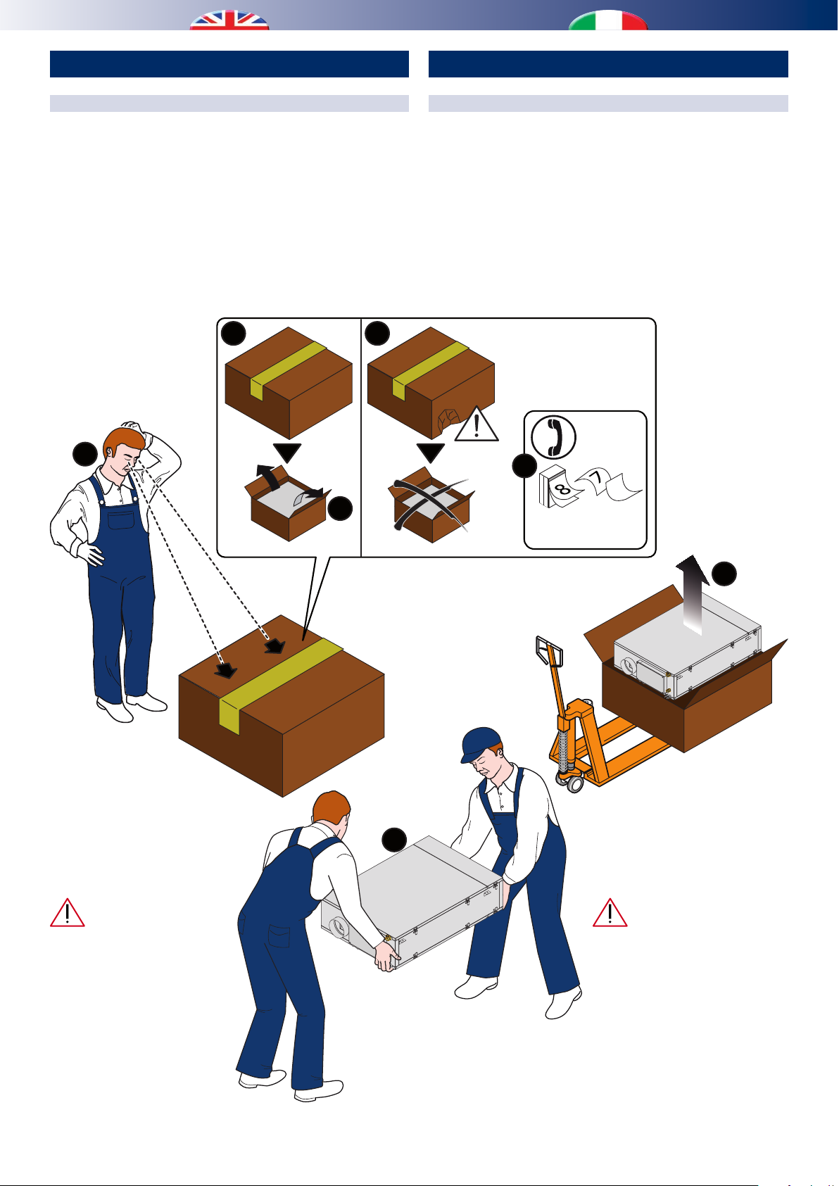
TESTING, TRANSPORT AND UNPACKAGING
Upon receipt, check immediately that the packaging is intact:
the machine has left the factory in perfect working order and any
damage must be notied to the carrier immediately and noted on
the Delivery Sheet before it is countersigned.
Within 8 days, the customer must notify the manufacturer of the
extent and type of the damage noted, making a written report:
always take note of the serial number which can be found on the
plate axed to the machine.
2a 2b
OK!
1
3a
ISPEZIONE, TRASPORTO E DISIMBALLO
All’atto del ricevimento vericare immediatamente l’integrità
dell’imballo: la macchina ha lasciato la fabbrica in perfetto stato,
eventuali danni dovranno essere immediatamente contestati
al trasportatore ed annotati sul Foglio di Consegna prima di
contrormarlo.
Il Cliente, entro 8 giorni, deve avvisare il Costruttore sull’entità
e la tipologia dei danni rilevati compilando un rapporto scritto:
riportare sempre anche il numero di matricola rilevabile dalla
targhetta posta a bordo macchina.
RDZ
3b
6
within 8 days
entro 8 giorni
The unit packaging must
be removed with care, ensuring
that the machine is not damaged.
The materials which make up the
packaging are different: wood,
cardboard, nylon etc.
Store them separately and
deliver them for disposal or,
where appropriate, recycling,
to the relevant companies, thus
reducing the environmental
impact.
OK!
4
5
L’imballo dell’unità deve
essere rimosso con cura evitando
di arrecare possibili danni alla
macchina.
I materiali che costituiscono
l’imballo sono di natura diversa:
legno, cartone, nylon, ecc.
Conservarli separatamente e
consegnarli per lo smaltimento o
l’eventuale riciclaggio, alle aziende
preposte allo scopo e ridurne così
l’impatto ambientale.
6
Page 7
DESCRIPTION OF THE EQUIPMENT DESCRIZIONE APPARECCHIATURA
Air renewal ow-rate from 80 to 160 m3/h can be set and Air renewal ow-rate from 80 to 160 m3/h can be set and
detected automatically through a user interface. detected automatically through a user interface.
Single unit made up of two parts: heat recovery module and air Single unit made up of two parts: heat recovery module and air
handling module (water condensed). The high-efficiency heat handling module (water condensed). The high-efficiency heat
Unità trattamento aria con recupero di calore ad alta ecienza e per
Air handling unit with high-eciency heat recovery
for summer dehumidication. Outside air ow-rate
and partial recirculation mode can be set accordingly.
Air renewal ow-rate from 80 to 160 m3/h can be set and
detected automatically through a user interface.
Single unit made up of two parts: heat recovery module and air
handling module (water condensed). The high-efficiency heat
recovery unit (>90%) is situated on the air outlet in counter current ow.
It shall be horizontally installed into the false ceiling, and it is equipped
with air outlets on the two shorter opposite sides, which means that
air ducts can be connected easily, and they can be installed in narrow
spaces. Optional operations: air renewal, ventilation, dehumidication,
controlled integration of summer/winter sensible power. This unit
includes 1 motorized damper, already assembled and wired, which
controls automatically the recirculation ow. It can be combined with
2 additional motorized dampers to avoid annoying outside air ows
(e.g. cold windy places).
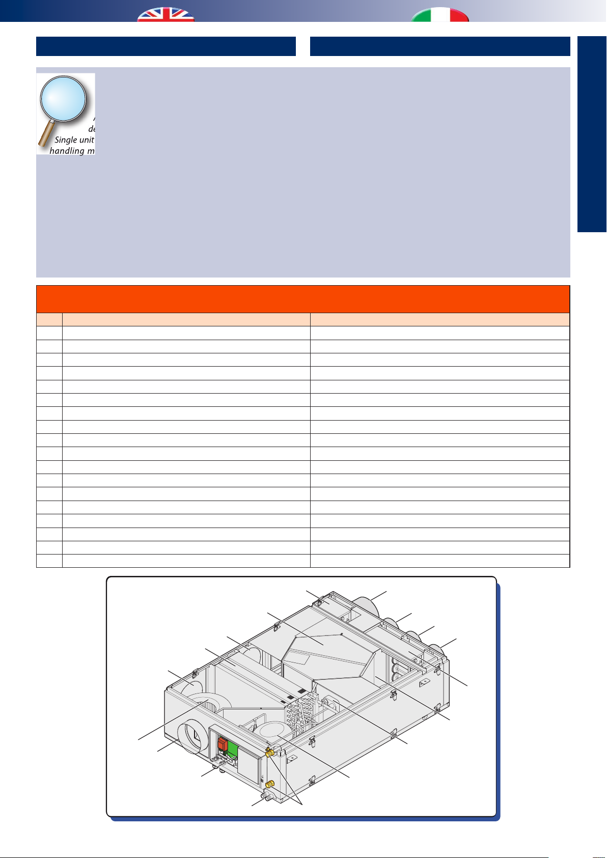
Table of machine components
Tabella dei componenti apparecchiatura
Rif. Descriptions Descrizione
A Inow Vent Bocchetta immissione
B Inow Fan Ventilatore di immissione
C Optional free-cooling vent 1 Bocchetta opzionale freecooling 1
D Finned coils Batterie alettate
E Optional free-cooling vent 2 Bocchetta opzionale freecooling 2
F Heat exchanger Scambiatore di calore
G Recirculation dumper Serranda ricircolo
H Room air intake vent for air recirculation Bocchetta ripresa aria ambiente per ricircolo
I Renewal air discharge vent Bocchetta espulsione aria rinnovo
J Outside air intake vent Bocchetta ripresa aria esterna
K Room air intake vent for air renewal Bocchetta ripresa aria ambiente per rinnovo
L Renewal optional dumper Serranda opzionale rinnovo
M Discharge fan Ventilatore di espulsione
N Heat exchanger condensed with water. Scambiatore condensante ad acqua
O Compressor Compressore
P Hydraulic connection Attacchi idraulici
Q Condensation drain Scarichi condensa
R Wiring box Quadro elettrico
trattamento di deumidicazione estiva, con impostazione portata
aria esterna ed eventuale funzionamento in parziale ricircolo.
Portata aria di rinnovo da 80 a 160 m3/h impostabile e rilevata
automaticamente tramite pannello utente.
Costruzione monoblocco con unione di 2 sezioni: sezione di
recupero e sezione di trattamento aria (condensata ad acqua).
Recuperatore di calore sull’aria di espulsione in controcorrente, ad
alta ecienza (>90%). Macchina costruita per montaggio orizzontale
in controsotto, dotata di attacchi aria sui 2 lati corti opposti, al
ne di facilitare le connessioni aerauliche e favorire l’installazione
in ubicazioni di limitata larghezza. Funzionalità di rinnovo aria,
ventilazione, deumidificazione, integrazione potenza sensibile
estiva e invernale (a comando). Unità equipaggiata con 1 serranda
motorizzata, già installata e cablata, che permette la regolazione
automatica del usso di ricircolo. Opzionalmente è possibile dotare
la macchina di 2 serrande motorizzate che permettono di evitare
indesiderati ussi di aria esterna (luoghi ventosi non protetti molto
freddi).
i - INFO
E
D
C
B
A
R
Q
G
F
H
I
J
K
L
M
N
O
P
7
Page 8

10
DESCRIZIONE CIRCUITI MACCHINAUNIT CIRCUIT DESCRIPTION
2
8
6
5
3
1
A
B C
4
7
9
Rif. Descriptions Descrizione
1 Inow fan Ventilatore immissione
2 Exhaust fan Ventilatore espulsione
3 Heat recover unit Recuperatore di calore
4 Air recirculation damper Serranda ricircolo
5 Optional damper Serranda opzionale
6 Compressor Compressore
7 Finned pack
A Pre-treatment coil
B Evaporation coil B Batteria evaporante
Pacco alettato
A Batteria pre-trattamento
C Condensation coil C Batteria condensante
8 Water/refrigerant exchanger Scambiatore a piastre
9 Expansion valve Valvole di espansione
10 Optional 3-way modulating valve Valvola modulante 3 vie opzionale
COMPONENTS DESCRIPTION
Components Description
Compressor Sealed
Phase clamp
250V- 8 A
fuse
Heat exchanger High efficiency cross-flow exchanger
(approximately 90%).
Plate exchanger Braze-welded plate exchanger built with AISI
316 stainless steel, used for condensation
in the chiller circuit, when integration is
requested
Control Unit Control unit used to manage temperatures,
pressures, to manage electric devices and
functions, in accordance with settable
parameters
Fans This is a double suction centrifugal fan directly
coupled to its motor
Filters Filter with synthetic bre ltering material,
class G3 (EN 779:2002)
DESCRIZIONE COMPONENTI
Componente Descrizione
Compressore Di tipo ermetico
Fusibile
250V- 8 A
morsetto fase
Scambiatore di
calore
Scambiatore a
piastre
Scambiatore ad alta ecienza (circa 90%) a
ussi incrociati.
Scambiatore a piastre saldobrasate in
acciaio inossidabile AISI 316, utilizzato per
la condensazione del circuito frigo, in caso
di richiesta di integrazione
Centralina Centralina per il controllo delle temperature,
pressioni, la gestione dei dispositivi elettrici
e delle funzionalità, secondo dei parametri
impostabili.
Ventilatori Di tipo centrifugo a doppia aspirazione con
motore direttamente accoppiato
Filtri Filtro con materiale ltrante in bra sintetica,
classe G3 (EN 779:2002)
8
Page 9

Components Description
Pre-treatment
coil
Evaporator coil Copper pipes with "hydrophilic" treated
Condenser coil Copper pipes with aluminium ns
Coolant gas R 134a
Copper pipes with "hydrophilic" treated
aluminium ns
aluminium ns
Componente Descrizione
Batteria pretrattamento
Batteria
evaporante
Batteria
condensante
Gas
refrigerante
Tubi in rame e alette in alluminio con
trattamento “idrolico”
Tubi in rame e alette in alluminio con
trattamento “idrolico”
Tubi in rame e alette in alluminio
R 134a
i - INFO
SAFETY CHECKS
All the control devices are tested in the factory before the equipment
is shipped. Their operation is described in the following paragraphs.
Safety check is carried out by the control unit through the values
measured by the probes:
• Delivery probe
This probe measures the delivery air temperature in a room, and
is installed on the mouth of the intake fan outlet.
• Evaporator probe
This probe measures the coolant evaporation temperature and
is installed on the pipe that leads out from the two electronic
thermostatic valves.
• SOTT_C1 probe
This probe measures the temperature of the coolant leaving the
condenser 1 (the one for the main air ow rate), and is installed
on the intake for electronic thermostatic valve A.
• SOTT_C2 probe
This probe measures the temperature of the coolant leaving
the plate condenser.
• Overheating probe
This probe measures the temperature of the coolant leaving the
evaporator, and is designed to assess whether the coolant ow
rate is suitable for the thermal load.
• H2O probe
This probes measures the intake water temperature, and is
installed on the system’s water intake pipe.
• Compressor temperature probe
This probe measures the coolant temperature leaving the
compressor, and is installed on the compressor delivery pipe.
• Coolant pressure transducer
This is installed on the compressor delivery pipe and is designed
to control the high pressure value of the chiller circuit and as an
approximate pressure switch.
• Pressure transducer for the renewal air ow rate
The sensor is installed on the electronic board and, through two
small PVC tubes, reads the dierential pressure between the
input and output of the static heat recovery unit, on the ow
rate of the air entering the room.
CONTROLLI DI SICUREZZA
Tutti i dispositivi di controllo sono collaudati in fabbrica prima
della spedizione dell’apparecchiatura. La loro funzionalità viene
descritta nei paragra successivi.
I controlli di sicurezza vengono eettuati dalla centralina tramite
i valori rilevati dalle sonde:
• Sonda di mandata
Sonda di misura della temperatura di immissione aria in
ambiente, è posta sulla bocca di uscita del ventilatore di
immissione.
• Sonda evaporatore
Sonda di misura della temperatura di evaporazione del
refrigerante, è posta sul tubo in uscita dalle due valvole
termostatiche elettroniche.
• Sonda SOTT_C1
Sonda di misura della temperatura del refrigerante in uscita
dal condensatore 1 (quello del usso principale dell’aria), è
posta all’ingresso della valvola termostatica elettronica A.
• Sonda SOTT_C2
Sonda di misura della temperatura del refrigerante in uscita
dal condensatore a piastre.
• Sonda surriscaldamento
Sonda di misura della temperatura del refrigerante in
uscita dall’evaporatore, serve per valutare se la portata di
refrigerante è adeguata al carico termico.
• Sonda H2O
Sonda di misura della temperatura di ingresso dell’acqua, è
posta sul tubo di ingresso dell’acqua dell’impianto.
• Sonda di temperatura del compressore
Sonda di misura della temperatura del refrigerante in
uscita dal compressore, è posta sul tubo di mandata del
compressore.
• Trasduttore della pressione del refrigerante
È posto sulla tubazione di mandata del compressore,
serve per controllare il valore di alta pressione del circuito
frigorifero e come pressostato di massima.
• Trasduttore di pressione del usso di aria di rinnovo
Il sensore è posto sulla scheda elettronica e tramite due
tubicini di PVC rileva la pressione dierenziale tra l’ingresso
e l’uscita del recuperatore di calore statico, sul usso di aria
entrante in ambiente.
9
Page 10
INSTALLATION INSTALLAZIONE
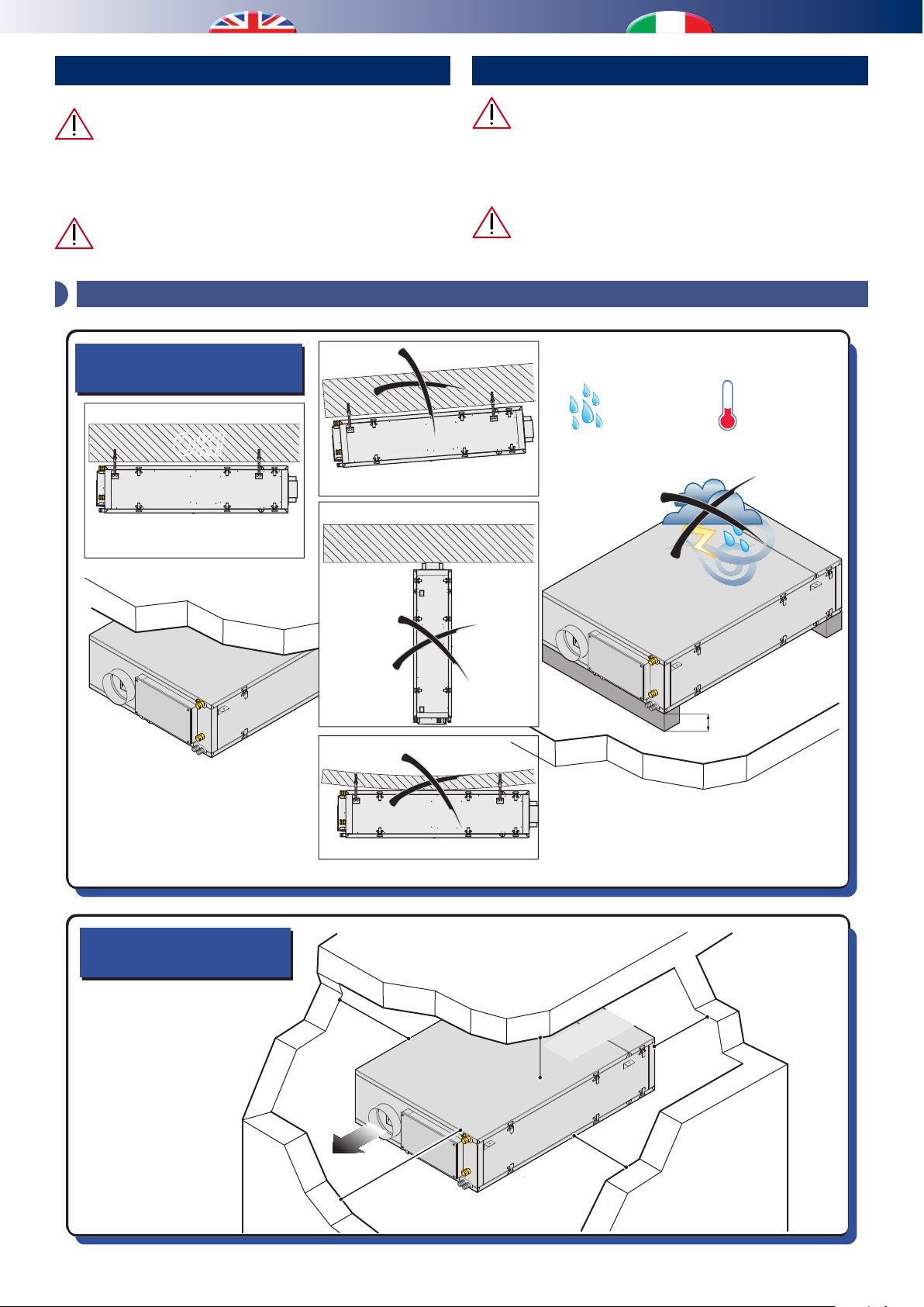
CAUTION
Installation and maintenance must be carried out by qualied
personnel only. Throughout installation, make sure that the
equipment is not connected to the electrical mains.
It shall be installed only inside the building.
1 - POSITIONING AND FIXING TO THE CEILING / POSIZIONAMENTO E FISSAGGIO A SOFFITTO
Positioning indications
Indicazioni di posizionamento
ATTENZIONE
L’installazione e la manutenzione vanno eseguiti solo
da personale qualicato. Durante tutte le procedure di
installazione, assicurarsi che l’apparecchiatura non sia
collegata alla rete elettrica.
L’installazione deve essere eettuata solo all’interno
degli edici
MAX 95%
OK!
MAX 30°C
Minimum space allowanceses
Distanze minime di rispetto
* min 40 cm with
free-cooling
* min 40 cm con
free-cooling
min.
20 cm*
min.
60 cm
no constraint
nessun vincolo
min.
20 cm
min.
20 cm
~ 10 cm
10
Page 11
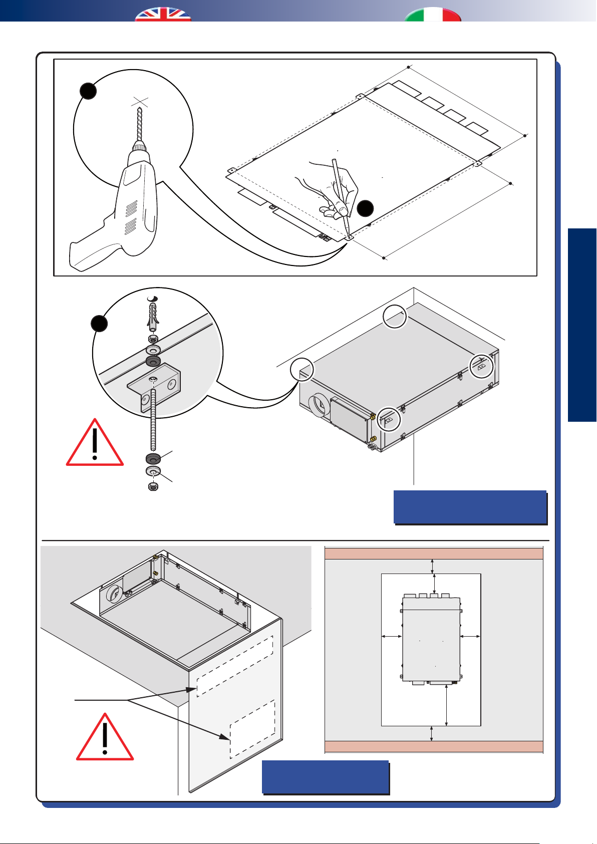
2
ø8mm
3
773
1
845,5
INSTALLATION
INSTALLAZIONE
Opening
Botolini
Rubber mounts
Gommino antivibrante
Washer
Rondella
Fixing to ceiling
Fissaggio a sotto
X
min.
20 cm
min.
20 cm
min.
60 cm
X
min.
20 cm
Trap door
Botola d’ispezione
11
Page 12

2 - HYDRAULIC CONNECTIONS / COLLEGAMENTI IDRAULICI
Hydraulic connection to a refrigerating unit capable
of supplying chilled water is indispensable. In this case, the
dehumidier can operate without varying the temperature of
the air treated with a considerable increase in yield.
It is necessary to create a drain-trap on the drain line,
considering a owrate of 15 l/h and minimum inclination of
9%, to avoid any air suck from the drain pipe.
After lling the system with water, it is advisable to
check that not only the connections but also the machine
hydraulic circuit are watertight, as these could be damaged
during transportation or on site during installation; on this
topic, the manufacturer will only be responsible for factory
defects on the dehumidifier and under no circumstances
accepts responsibility for indirect damage.
The condensation drain and the inlet and outlet pipes
must comply with the standards and laws in force in
the country of use.
L’allacciamento idraulico ad un gruppo frigo in grado
di fornire acqua refrigerata risulta indispensabile.
In tale caso il deumidicatore potrà operare senza variare la
temperatura dell’aria trattata con un sensibile incremento
di resa.
È necessario realizzare un sifone sulla linea di scarico,
dimensionato per una portata di 15 l/h e avente una
pendeza minima del 9%, per evitare il risucchio di aria dal
tubo di scarico.
Dopo aver riempito d’acqua l’impianto si raccomanda
di verificare attentamente la tenuta non solo dei
collegamenti ma anche del circuito idraulico della
macchina, che potrebbe essersi danneggiato nel trasporto
o in cantiere durante l’installazione; a tale proposito
il costruttore risponderà esclusivamente dei difetti “di
fabbrica” del deumidicatore e in ogni caso non si assume
nessuna responsabilità per danni indiretti.
Lo scarico condensa e le tubazioni di ingresso e
uscita devono rispondere alle norme e leggi vigenti
nel paese di utilizzo.
HYDRAULIC CONNECTION
CONNESSIONI IDRAULICHE
A
B
C
D
Rif. Description Descrizione
Pre-treatment water outlet (1/2”F) with cut-o valve to
A
adjust ow rate
Pre-treatment water inlet (1/2”F) with lockshield to adjust
B
ow rate
C Ø20 mm drain for dehumidication condensation
D Ø20 mm drain for recovery unit condensation
Uscita acqua pre-trattamento (1/2”F) con valvola di
intercettazione per regolazione portata
Ingresso acqua pre-trattamento (1/2”F) con detentore
di regolazione portata
Scarico in portagomma ø20 mm per condensa
deumidicazione
Scarico in portagomma ø20 mm per condensa
recuperatore
Use piping whose sizes are appropriate for the
ow rate required.
Utilizzare tubazioni di misura adeguata in
funzione delle portate desiderate.
It is better to install on-off valves for the
sectioning of the supply pipe of cold water.
Si consiglia di predisporre delle valvole di
intercettazione per il sezionamento delle linee
di alimentazione dell’acqua refrigerata.
12
Page 13

WATER OUTLET
RITORNO
WATER INLET
MANDATA
HYDONIC CONNECTION
CONNESSIONI IDRONICHE
Vent valve
Valvola di sato
1/2” F
Gasket
Guarnizioni
Summer drain
Scarico estivo
Winter drain
Scarico invernale
Discharge NOT
in ascent!
Scarico NON
in salita!
CONDENSATION DRAIN
SCARICO CONDENSA
INSTALLATION
INSTALLAZIONE
9%
13
Page 14
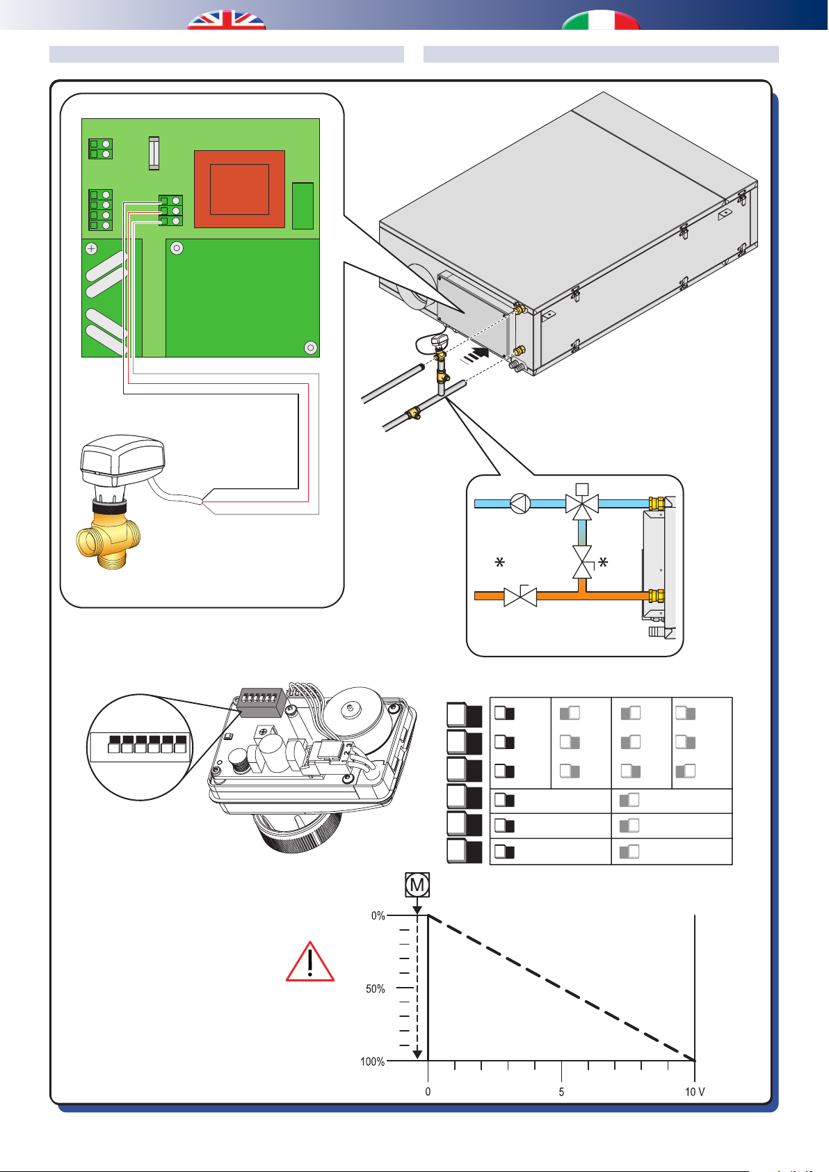
OPTIONAL H2O VALVE CONNECTION COLLEGAMENTO VALVOLA H2O OPZIONALE
Fuse
220V AC
MOD bus
Fusibile
N
L
P1
GND
A
B
+ V
P2
GND
24V
SIGN
H
8A
O valve
2
P3
ON
OFF
123456
Right
conguration
Congurazione
corretta
Black / Nero
Red / Rosso
Grey / Grigio
ON
1
2 3 4
5 6
OFF
ON
1 2 3 4 56
AB A
Kv 3.02
0...10VDC
DA
LIN
VDC
0...20mA
B
0...5VDC
5...10VDC
RA
Eq%
mA
2...10VDC
4...20mA
0 V = AB -> A
10 V = AB -> B
14
Page 15

3 - ELECTRICAL CONNECTIONS / COLLEGAMENTI ELETTRICI
The dehumidier must be connected to a disconnected,
earthed power socket. The electrical system must be protected
against overloads, short circuits and direct and indirect
contacts and comply with the laws and regulations in force in
the country of use. Electrical interventions must be performed
by qualied personnel.
The electrical power line must be protected by a residual
current device.
Check that the power supply voltage corresponds to
the rated unit data (voltage, number of phases, frequency)
shown on this manual and on the plate on the machine. The
power connection takes place through a bipolar cable plus
earth. The power supply voltage is not subject to variations
greater than ±5%.
Operation must take place within the aforementioned
values: if this is not the case, the warranty is invalidated
immediately, and there are electrical risks for people and
for the product.
DOOR OPENING
Il deumidificatore deve essere collegato ad una
presa di corrente sezionata provvista di terra. L’impianto
elettrico di alimentazione deve essere protetto contro i
sovraccarichi, i cortocircuiti, i contatti diretti ed indiretti,
conformemente alle leggi e norme vigenti nel paese di
utilizzo. Gli interventi elettrici devono essere eettuati da
personale qualicato.
La linea elettrica di alimentazione deve essere
protetta da un interruttore dierenziale magnetotermico.
Verificare che la tensione di alimentazione
corrisponda ai dati nominali dell’unità (tensione, numero
di fasi, frequenza) riportati in questo manuale e sulla
targhetta a bordo macchina. L’allacciamento di potenza
avviene tramite cavo bipolare più terra. La tensione di
alimentazione non deve subire variazioni superiori a ±5%.
Il funzionamento deve avvenire entro i valori sopra
citati: in caso contrario la garanzia viene a decadere
immediatamente e ci sono rischi elettrici per le persone e
il prodotto.
APERTURA SPORTELLO
INSTALLATION
INSTALLAZIONE
1
2
15
Page 16

POWER SUPPLY
ALIMENTAZIONE
Connect the 3 terminals with 3x1.5mm³ cable:
phase (F)
neutral (N)
earth
The terminal of the tension line is provided with 8 A
fuse; if the unit does not start even though it is energized,
check this fuse.
1
Portare e collegare con cavo 3x1.5mmq i 3 morsetti:
fase (F)
neutro (N)
terra
Il morsetto di linea dell’alimentazione elettrica è
dotato di fusibile da 8 A, in caso di non avviamento della
macchina ma presenza di tensione vericare il fusibile.
2
3
16
Page 17

4 - CONNECTION TO THE CONTROL UNITS / COLLEGAMENTI ALLE CENTRALINE DI COMANDO
Fuse
Fusibile
220V AC
8A
N
L
P1
MOD bus
P3
O valve
2
H
GND
24V
SIGN
AB+ V
GND
P2
NTC1
NTC2
K3
KC
K2
K1
AnOut1
AnIn1
CC
A
B
+ V
GND
AB
PC 300 Control Panel
TX+
TXPWR+
PWR-
TYPE 2
INSTALLATION
INSTALLAZIONE
TIPO 2
serial card 1
WI-SA Serie Design
!
GND
AV+
B
!
Remote Control - TYPE 1
Controllo Remoto - TIPO 1
17
Page 18

A
B
E
F
G
H
MODBUS ADDRESS SETTING SETTAGGIO INDIRIZZO MODBUS
Remote Control - Type 1
Controllo Remoto - TIPO 1
K2K3KC
NTC2
K1
NTC1
AnIn1
AnOut1
TX-
CC
TX+
PWR+
PWR-
PC 300 Control Panel
TYPE 2
TIPO 2
serial card 1
WI-SA Serie Design
Unit 1 Unit 2
Unità 1Unità 2
!
!
18
Page 19

5 - AERAULIC CONNECTIONS / COLLEGAMENTI AERAULICI
It is recommended to use a silencer in the supply duct.
Si consiglia di prevedere un silenziatore sul canale
di mandata agli ambienti
Ø145
Immissione ambienti
Supply to the room
Ø150 Ø150
POST PRE
Free-Cooling
INSTALLATION
INSTALLAZIONE
19
Ø100
Ø100
Outdoor air intake
WC / Kitchen intake
Ripresa aria esterna
Ripresa WC / Cucina
Ø100
Espulsione
Ø145
Exhaust
Ripresa da ambienti puliti
Clean room intake
Page 20

6 - FREE-COOLING CONFIGURATION / CONFIGURAZIONE FREE-COOLING
FREE-COOLING POST
(Outdoor air inow after the nned pack)
(ingresso aria esterna dopo il pacco alettato)
Finned pack
Pacco alettato
FREE-COOLING PRE
(Outdoor air inow before the nned pack)
(ingresso aria esterna prima del pacco alettato)
Finned pack
Pacco alettato
20
Page 21

POST
BLACK
COM
BROWN
L1 24V
S1 24V
RED
Dumper servomoto
Servomotore serranda
PIN conguration
Congurazione PIN
Servomotore serranda
Free-Cooling
24Vac 3 Point
24Vac 3 Punti
OK
OK
Install a lter in the outdoor air intake duct
Prevedere un ltro lungo il canale di apirazione aria esterna
INSTALLATION
INSTALLAZIONE
PRE
BLACK
COM
BROWN
L1 24V
S1 24V
RED
Dumper servomotor
Servomotore serranda
WARNING: This conguration of the jumper, with POST
installation, can damage the unit
ATTENZIONE: Questa congurazione del jumper, con
l’installazione “POST”, può danneggiare l’unità
PIN conguration
Congurazione PIN
24Vac 3 Point
24Vac 3 Punti
OK
OK
Install a lter in the outdoor air intake duct
Prevedere un ltro lungo il canale di apirazione aria esterna
21
Page 22
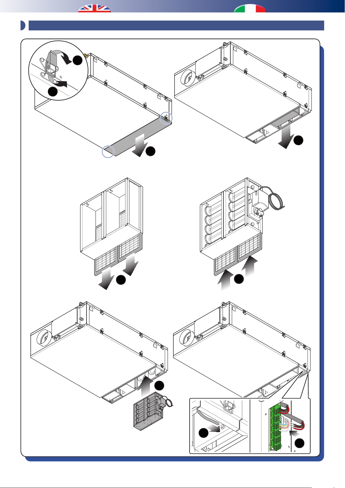
7 - OPTIONAL DUMPER INSTALLATION / INSTALLAZIONE SERRANDE OPZIONALI
1
2
3
4
5
6
7
8
9
22
Page 23
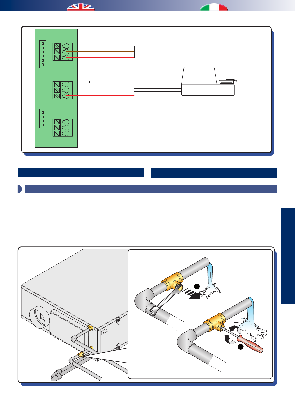
P1
P2
K2 K1
K3
COM
L1+24V~
S1+24V~
black / nero
brown / marrone
red / rosso
black / nero
brown / marrone
red / rosso
ACTUATOR FOR ROOM INTAKE DAMPER
ATTUATORE SERRANDA RIPRESA AMBIENTI
ACTUATOR FOR OPTIONAL DAMPER
ATTUATORE SERRANDA OPZIONALE
START-UP AND TESTING
AVVIAMENTO E COLLAUDO
1 - HYDRAULIC CIRCUIT ADJUSTING / TARATURA CIRCUITO IDRAULICO
The dehumidier must be tested together with the panel system in
summer operating mode; the main check which must be performed
regards the cooling water ow rate which must be approximately
400 l/h when the water temperature is approximately 15 °C. By
using lower temperatures, water ow rates will be inferior too.
Il collaudo del deumidificatore andrebbe effettuato
contestualmente a quello dell’impianto a pannelli in
funzionamento estivo; la principale verifica da effettuare
riguarda la portata dell’acqua di rareddamento che dovrebbe
essere di circa 400 l/h quando la temperatura dell’acqua è di
circa 15 °C. Con temperature dell’acqua più basse, anche le
portate devono essere inferiori.
USE
UTILIZZO
1
23
2
Page 24

WATER FLOW SETTING
TARATURA PORTATE ACQUA
In case you cannot detect the exact ow ratem, you can consider
the followingg procedure:
Air recirculation mode
- Set “Room ow rate” at 100 %
- Switch on the unit in the air recirculation mode
- Wait for few minutes
- Check the inow temperature and humidity
(this test is not valid if temperature is lower than 26 °C)
- Check the temperature detected by the supply sensor
In case of high humidity (26 °C 65 % R.H. or 28 °C 60 % R.H.) the air
output temperature shall be around 18 °C, while in case of lower
humidity, the supply temperature shall be around 17 °C.
Fresh air ventilation mode
- Set “Fresh air ventilation ow rate” at 160 m³/h
- Switch on the unit in the fresh air ventilation mode
- Wait for few minutes
- Check the inow temperature and humidity
- Check the temperature detected by the supply sensor
In case of outdoor conditions at 35 °C 50 % R.H. the air output
temperature shall be around 18 °C
In case of outdoor conditions at 33 °C 50 % R.H. the air output
temperature shall be around17 °C
Nel caso in cui non sia possibile rilevare con esattezza la portata,
si può utilizzare questa procedura:
Funzionamento ricircolo
- Settare “Portata ambiente” a 100 %
- Attivare l’unità in modalità di solo ricircolo
- Attendere qualche minuto
- Vericare la temperatura e umidità in ingresso all’unità
(questa prova non è valida con temperature inferiori ai 26 °C)
- Vericare la temperatura rilevata dalla sonda di mandata
Con umidità gravose (26 °C 65 % U.R. oppure 28 °C 60 % U.R.) la
temperatura di uscita dell’aria deve essere di circa 18 °C, mentre
con umidità più confortevoli, la temperatura di mandata
rilevata deve essere di circa 17 °C.
Funzionamento rinnovo
- Settare “Portata rinnovo” a 160 mc/h
- Attivare l’unità in modalità di solo rinnovo
- Attendere qualche minuto
- Vericare la temperatura e umidità in ingresso all’unità
- Vericare la temperatura rilevata dalla sonda di mandata
Con condizioni esterne di 35 °C 50 % U.R. la temperatura di
uscita dovrà essere di circa 18 °C
Con condizioni esterne di 33 °C 50 % U.R. la temperatura di
uscita dovrà essere di circa 17 °C
Combined mode (recirculation+ventilation)
- Use the previous setting
- Switch on the unit in the recirculation+ventilation mode
- Wait for few minutes
- Check the inow temperature and humidity
- Check the temperature detected by the supply sensor
In case of outdoor conditions at 35 °C 50 % R.H. the air output
temperature shall be around19 °C
Very low ow rate values can cause malfunctioning in
UC 300-M unit and they can activate relevant alarms. In
this case the unit stops working and shall be restarted
manually.
Do not use the dehumidier without the chilled water:
this may damage the machine itself!
Funzionamento combinato (ricircolo+rinnovo)
- Con i set precedentemente impostati
- Attivare l’unità in modalità di ricircolo + rinnovo
- Attendere qualche minuto
- Vericare la temperatura e umidità in ingresso all’unità
- Vericare la temperatura rilevata dalla sonda di mandata
Con condizioni esterne di 35 °C 50 % U.R. e condizioni ambientali
di 26 °C 65 % U.R. la temperatura di uscita dovrà essere di circa
19 °C
Portate insufficienti, inversamente, causano
malfunzionamenti all’unità UC 300-M e l’attivazione
di allarmi con blocco macchina a riarmo manuale.
Non utilizzare il deumidificatore senza l’acqua
refrigerata: questo può portare al danneggiamento
della macchina stessa!
24
Page 25
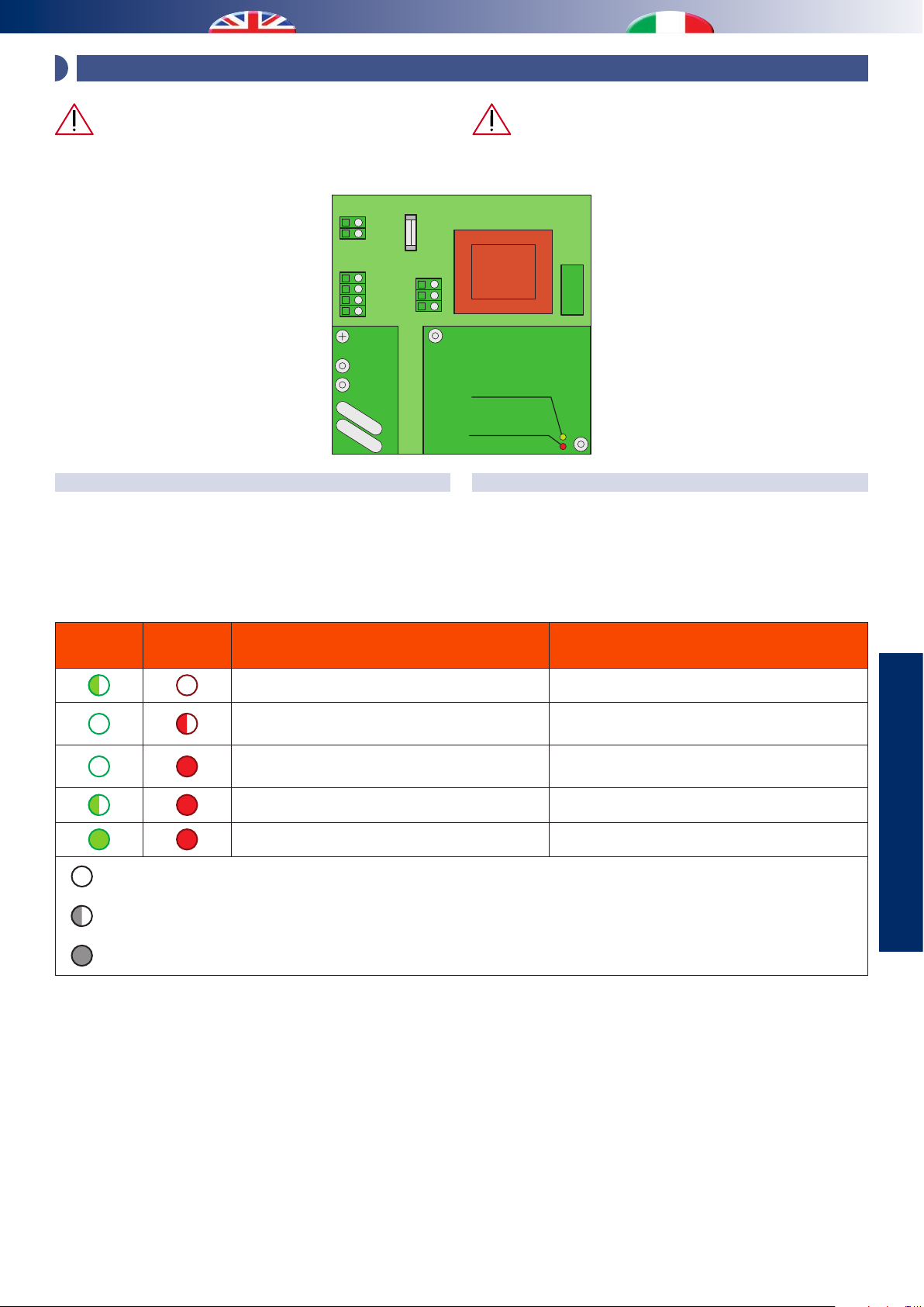
2 - UNIT STARTING / ACCENSIONE MACCHINA
Before switching on the unit, make sure that wiring
connection has been carried out in the right way.
Fuse
220V AC
MOD bus
Fusibile
N
L
P1
GND
A
B
+ V
P2
GND
24V
SIGN
H
8A
O valve
2
P3
VISUAL SIGNALS
On the electronic board there are two leds, one red and one green.
When the power supply on the electronic board is switched on it
starts a “boot” procedure of 120 second duration and during this
procedure the green led keeps on.
Prima di accendere la macchina, assicurarsi che
tutti i collegamenti elettrici siano stati realizzati in
maniera corretta.
Green LED
LED Verde
Red LED
LED Rosso
SEGNALAZIONI VISIVE
Sulla scheda elettronica a bordo macchina vi sono due led, uno
verde ed uno rosso. Quando viene data tensione alla scheda
essa eettua una procedura di “boot” che dura circa 120 secondi
e durante tale fase il led verde, e solo quello, rimane illuminato
continuo.
Green led
Led verde
Red led
Led rosso
Led o / Led spento
Led ashing / Led lampeggiante
Led on / Led acceso
Meaning Signicato
Boot start Fase iniziale di Boot
Serial communication with the controller failed
- The unit is ready for setting
- Operating without compressor
Compressor is ready to be started Attesa attivazione compressore
Compressor is working Compressore attivo
Mancanza di comunicazione seriale con la
centralina di comando
- Macchina pronta per ricevere comandi
- Funzionamento senza compressore
USE
UTILIZZO
25
Page 26

3 - PARAMETERS SETTING / SETTAGGIO PARAMETRI
Since UC 300-M unit is a versatile solution which can be suited to
very dierent applications, the setting of the controller parameter
is very important according to the system configuration, the
features of the building and the users’ requirements.
Independently of the kind of controller, the unit parameters are
always the same.
System parameters
Operation Default values and notes
Modulating valve Disabled
Winter integration Enabled
Free-Cooling
Season contact
Disabled as default
(always enabled in controller type 1)
Disabled as default
(unavailable in controller type 2)
Building parameter
(to be set only upon designer’s instructions)
Operation Default values and notes
Room ow rate 40 %
3
Ventilation ow rate 120 m
Boost ow rate 50 %
Boost switch-o delay 1 min
Air ow rate
Free-cooling ow rate 50 %
Summer inow temp. 25 °C
Summer integration
dierence
Winter inow temp.
Winter integration
Inow temperature
dierence
/h
6 °C
21 °C (it can be changed only if
the modulating valve is used)
10 °C (it can be changed only if
the modulating valve is used)
Essendo l’UC 300-M una macchina versatile e adattabile a
più situazioni, si rende necessario il settaggio dei parametri
della centralina in base alla conformazione dell’impianto, alle
caratteristiche dell’unità abitativa e alle necessità dell’utenza
nale.
Indipendentemente dal tipo di controllore presente, i parametri
macchina sono sempre analoghi.
Parametri impianto
Funzione Default e note
Valvola modulante Disabilitata
Integrazione invernale Abilitata
Free-Cooling
Contatto stagionalità
Disabilitato di default
(sempre abilitato su controllo Tipo 1)
Disabilitato di default
(assente su controllo Tipo 2
Parametri unità abitativa
(Da regolare solo su una base di progetto o
indicazioni del progettista)
Funzione Default e note
Portata ambiente 40 %
3
Portata rinnovo 120 m
Portata boost 50 %
Ritardo spegnimento
boost
Portate aria
Portata free-cooling 50 %
Temp. mandata estiva 25 °C
Delta integrazione est. 6 °C
Temp. mandata invern.
immissione
Temperature
Delta integrazione inv.
/h
1 min
21 °C (modificabile solo in
presenza della valvola)
10 °C (modificabile solo in
presenza della valvola)
Users’ parameters
Operation Default
Reduction of the owrate values in Economy mode - 20 %
Operation time slots
Parametri necessità utenza
Funzione Default
Attenuazione Portate in funzionamento Economy - 20 %
Fasce orarie di funzionamento
26
Page 27

FUNCTIONING FUNZIONAMENTO
1 - OVERVIEW / PANORAMICA
Some functions of the machines, with their special details
highlighted, are summarised below.
Recirculation
This function only activates the delivery fan, therefore recirculating
the air in the room. Recirculation can be managed with
dierentiated ow rates, according to the set programme schedule
(“Normal” and “Economy” functions).
Fresh air ventilation
This function switches on the supply fan, the extract fan and the
dampers in order to take in fresh outdoor air and supply it into the
rooms, while extracting warm air from wet rooms and exhausting
it to the outside. Renewal can be managed with dierentiated ow
rates, according to the set programme schedule (“Normal” and
“Economy” functions).
Dehumidication
When this function is on, the chiller circuit is enabled and, unless
the “renewal contact” is closed, the recirculation mode will start
up by default. This function is only possible in summer season.
Integration
The “integration” function acts dierently according to the season:
• WINTER: its operation depends on the use of a modulating valve
on the hydraulic supply;
1. if the modulating valve is provided, the delivery air temperature
is controlled by the desired value (winter integration
temperature);
2. if there is no modulating valve, the integration function
is activated without temperature control (integration will
therefore depend on the temperature and ow rate of the
supply water).
• SUMMER:
The request for integration starts up the refrigerant circuit and the
inow fan. The intake air temperature is managed by the control
board, modulating the refrigerant circuit to maintain the correct
set point. The surplus heat is drained by the water condenser.
Di seguito vengono schematizzati alcuni funzionamenti della
macchina evidenziandone le particolarità.
Ricircolo
Questa funzione attiva il solo ventilatore di immissione
ricircolando quindi l’aria ambiente. Il ricircolo può essere
gestito con portate dierenziate, secondo un programma orario
impostato (funzionamenti “Normale” ed “Economy”).
Rinnovo
Questa funzione attiva sia il ventilatore di immissione che il
ventilatore di espulsione, attiva le serrande in modo da aspirare
aria esterna da immettere in ambiente e prelevare aria sporca
da espellere verso l’esterno. Il rinnovo può essere gestito con
portate dierenziate, secondo un programma orario impostato
(funzionamenti “Normale” ed “Economy ”).
Deumidicazione
Quando è attiva questa funzionalità viene attivato il circuito
frigorifero e di default parte la modalità ricircolo. Questo
funzionamento è previsto per la sola stagione estiva.
Integrazione
La funzionalità “integrazione” agisce diversamente a seconda
della stagione:
• INVERNO: il funzionamento dipende dalla presenza o assenza
della valvola modulante sull’alimentazione idraulica;
1. Se è presente, la temperatura dell’aria di immissione viene
controllata al valore di set impostato, agendo sulla portata
dell’acqua di alimentazione;
2. Se non è presente, la funzionalità integrazione viene attivata
senza controllo di temperatura (l’integrazione dipenderà
quindi dalla temperatura e dalla portata dell’acqua di
alimentazione).
• ESTATE:
La richiesta di integrazione attiva il circuito frigorifero e
il ventilatore di immissione. La temperatura dell’aria di
immissione viene gestita dalla centralina, modulando il
circuito frigorifero in modo da mantenere il valore di set
impostato. Il calore prodotto in eccesso dal circuito frigorifero
verrà poi smaltito nel condensatore ad acqua.
USE
UTILIZZO
Boost
The booster starts up renewal and fans, based on the specications
for “Boost” mode: this allows the user to increase, if they so wish,
the fresh air ow rate to take away odours and pollutants quickly.
Free-Cooling
During the free-cooling mode the unit activates the fans and opens
the free-cooling damper to force the outside air through the bypass duct instead of passing through the exchanger.
Note: Boost and fresh air renewal functions do not
substitute extractor hood installed in kitchen or other
rooms.
Do not connect directly extractor hood and UC300-M
Boost
Il booster attiva la modalità di rinnovo e i ventilatori secondo
i parametri impostati per la funzione “Boost”: ciò permette di
avere, se desiderato, un aumento delle portate di ricambio aria
per una veloce evacuazione di odori e di inquinanti.
Free-Cooling
Nel funzionamento free-cooling, l’unità attiva i ventilatori e
tramite l’apposita serranda di free-cooling devia l’aria aspirata
esternamente verso il canale di by-pass senza essere così
processata dallo scambiatore di calore.
Nota: La funzione Boost e in generale quelle di
rinnovo non sostituiscono l’eventuale cappa di
aspirazione in cucina o altro locale.
Evitare nel modo più assoluto il collegamento diretto
tra cappa aspirante e UC 300-M
27
Page 28
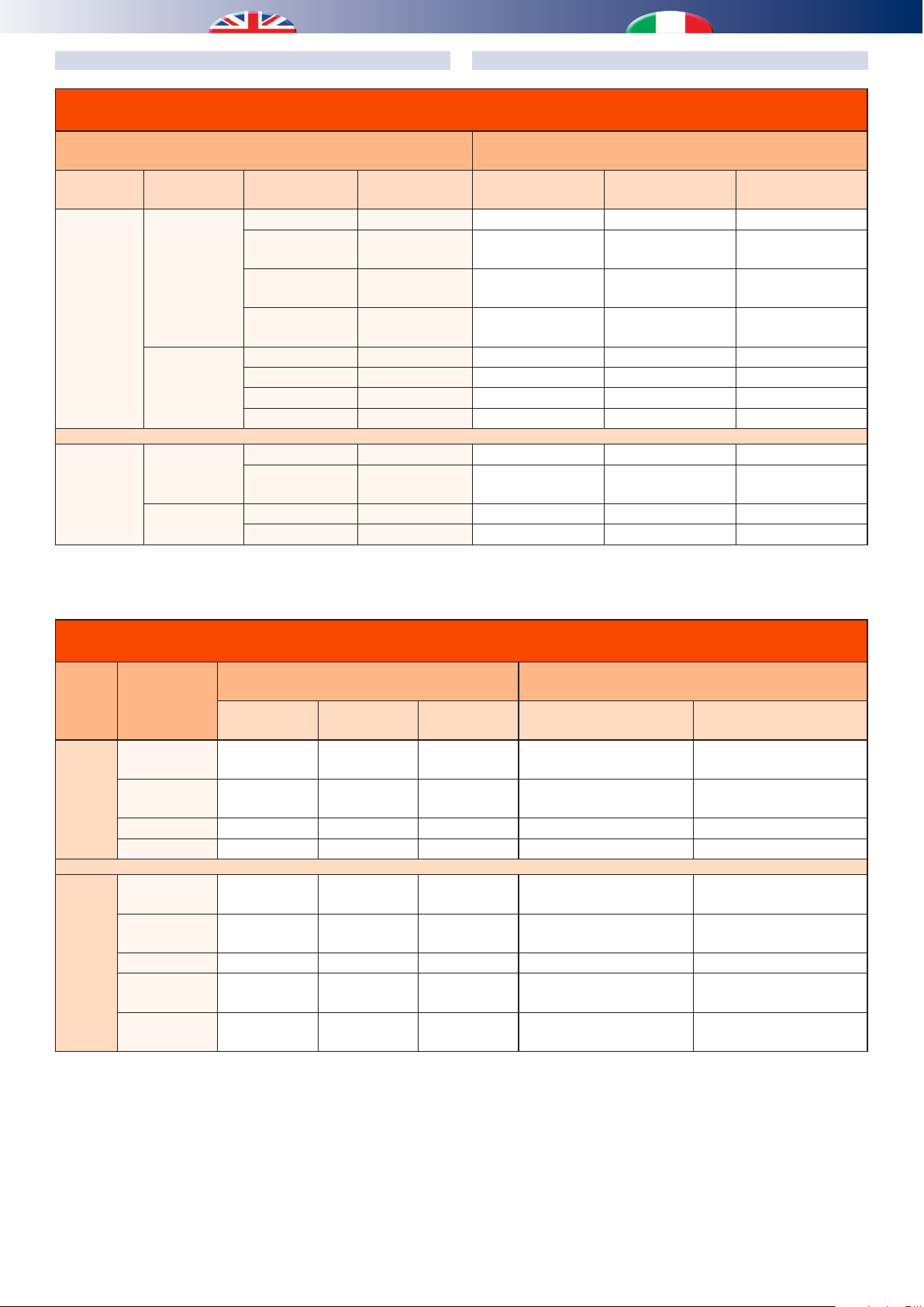
Truth table about hydraulic/refrigerating mode
Tabella di verità delle funzionalità idraulico/frigorifere
Input settings
Impostazioni di input
Season
Stagione
Summer
Estate
O valve
H
2
Valvola H2O
Enabled
Abilitata
Disabled
Disabilitata
Dehumidic.
Deumidica
Integration
Integrazione
OFF OFF OFF OFF
OFF ON ON
ON OFF ON
ON ON ON
OFF OFF OFF - OFF
OFF ON ON - ON
ON OFF ON - ON
ON ON ON - ON
TABELLE FUNZIONAMENTI MACCHINAUNIT FUNCTION TABLE
Compressor
Compressore
Components
Componenti
Valve mode
Stato valvola
(1)
All open
Tutta aperta
All open
Tutta aperta
All open
Tutta aperta
Pump consent
Comando pompa
(2)
OFF
ON
ON
ON
Enabled
Winter
Inverno
Abilitata
Disabled
Disabilitata
(1)
Modulate during ventilation request
(2)
ON during ventilation request
- OFF OFF OFF
- ON OFF
- OFF OFF - OFF
- ON OFF - ON
Truth table about aeraulic mode
Tabella di verità delle funzionalità aerauliche
Dumper
Compr.
OFF
ON
Mode
Modalità
Recirculation
Ricircolo
Renewal
Rinnovo
Boost
(1)
(1)
(1)
SR
Open Close Close
Close Open Close
Close Open Close Boost Boost
Free Cooling Close Open Open Free-cooling Free-cooling
Recirculation
Ricircolo
Renewal
Rinnovo
Open Close Close
Modulate
Modula
Boost Close Open Close 160 m
PRE Free
Cooling
(2)
POST Free
Cooling
(3)
Close Open Open 160 m3/h 160 m3/h
Open Close Close
Serrande
Optional
Opzionale
Open Close
(1)
Modula se richiesta ventilazione
(2)
ON se richiesta ventilazione
F.C.
Ventilatore immissione
Inow fan
Room
Ambiente
Renewal
Rinnovo
Room
Ambiente
Room
Ambiente
3
/h 160 m3/h
Room
Ambiente
(1)
Modulate
Modula
Air ow rate
Portate d’aria
Ventilatore espulsione
(2)
OFF
ON
Discharge fan
OFF
Renewal
Rinnovo
OFF
Renewal
Rinnovo
OFF
SR: Recirculation dumper
(1)
With enabled valve H2O pump control is also activated while
it is possible to modulate water ow rate in order to ensure set
air temperature
(2)
With jumper in horizontal position only
(3)
With jumper in vertical position only
SR: Serranda ricircolo
(1)
Con valvola H2O abilitata attiva anche il comando pompa
e modula sulla portata dell’acqua, al ne di garantire la
temperatura di set dell’aria in uscita.
(2)
Con jumper in posizione orizzontale
(3)
Con jumper in posizione verticale
28
Page 29

Advanced functionings table
Tabella funzionamenti avanzati
Combined functioning
Funzionamento combinato
Renewal
Rinnovo
Dehumidication
Deumidicazione
Recirculation
Ricircolo
Renewal
Rinnovo
Dehumidication
Deumidicazione
Integration
Integrazione
Boost
Integration
Integrazione
Boost
Free-cooling
PRE / POST
Dehumidication
Deumidicazione
Integration
Integrazione
Boost
Free-cooling PRE /
POST
Integration
Integrazione
Boost
Free-Cool. PRE
Free-C. POST
Boost
Free-Cool. PRE
Free-C. POST
Free-cooling
PRE / POST
Season
Stagione
Sum / Win
Est / Inv
Summer
Estate
Summer
Estate
Winter
Inverno
Sum / Win
Est / Inv
Sum / Win
Est / Inv
Summer
Estate
Summer
Estate
Winter
Inverno
Sum / Win
Est / Inv
Sum / Win
Est / Inv
Summer
Estate
Summer
Estate
Summer
Estate
Summer
Estate
Summer
Estate
Winter
Inverno
Summer
Estate
Winter
Inverno
Sum / Win
Est / Inv
Sum / Win
Est / Inv
VI VE CO VA PI SFC
PA PR -
PA - ON
PA - ON
PA - -
PB PB -
/ -
ON ON
/
ON
/
ON
/
ON
ON -
ON -
ON -
/ -
ON ON
PA PF - - - ON
PA PR ON
PA PR ON
PA PR -
PB PB -
/
ON
/
ON
/
ON
ON -
ON -
ON -
/ -
ON ON
PR PR - - - ON
PA - ON
3
160 m
/h 160 m3/h ON
3
160 m
/h 160 m3/h ON ON ON ON
ON
ON
/
/
ON -
ON -
Dehumidication only, switch o Free-cooling
Solo deumidicazione, Free-cooling inibito
3
/h 160 m3/h ON
160 m
3
160 m
/h 160 m3/h -
3
160 m
/h 160 m3/h ON ON ON ON
ON
ON
/
/
ON -
ON -
Free-cooling only, inhibited Integration
Solo Free-cooling, Integrazione inibita
Free-cooling only, inhibited Integration
Solo Free-cooling, Integrazione inibita
PB PB - - - ON
-
-
-
USE
UTILIZZO
VI = Inow fun
VE = Discharge fun
CO = Compressor
PI = System circulation pump
VA = Water valve (“/” = valve disabled)
SFC = Free-cooling dumper
PA = Room ow rate
PR = Renewal ow rate
PB = Boost ow rate
PF = Free-cooling ow rate
VI = Ventilatore immissione
VE = Ventilatore espulsione
CO = Compressore
PI = Pompa impianto
VA = Valvola acqua (“/” = valvola non abilitata)
SFC = Serranda free-cooling
PA = Portata Ambiente
PR = Portata Rinnovo
PB = Portata Boost
PF = Portata Free-cooling
29
Page 30

2 - FLOW RATE DIAGRAM / SCHEMI GRAFICI GESTIONE PORTATE ARIA
VMCMV
Supply to the room
Immissione ambienti
Heat exchanger
Recuperatore
di calore
Exhaust
Espulsione
Outdoor air intake
Ripresa aria esterna
WC / Kitchen intake
Ripresa WC / Cucina
Feature Value
Ventilation Settable ow rate
Booster % setting to be added to the ventilation value
Free-Cooling
Feature
% setting to the range
3
(0% = 80 m
/h, 100% = 160 m3/h)
Range [ m
Min Max
3
/h ]
Renewal 80 160
Booster Ventilation set 160
Free-Cooling 80 160
Supply to the room
Immissione ambienti
Finned pack
Pacco alettato
Funzionalità Valore
Rinnovo Portata impostabile
Free-Cooling
CONDIZIONAMENTO MANDATA AMBIENTEAIR HANDLING ROOM SUPPLY
Heat exchanger
Recuperatore
di calore
Booster Impostazione % di maggiorazione su rinnovo
Impostazione % su range
3
(0% = 80 m
Funzionalità
/h, 100% = 160 m3/h)
3
Range [ m
/h ]
Min Max
Rinnovo 80 160
Booster Set Rinnovo 160
Free-Cooling 80 160
Clean room intake
Ripresa da ambienti puliti
Feature Value
One setting
Feature
Dehumidication
Integration
% setting to the range
3
(0% = 160 m
/h, 100% = 300 m3/h)
Range [ m
Min Max
160 300
3
/h ]
Funzionalità Valore
Set unico
Funzionalità
Deumidicazione
Integrazione
30
Impostazione % su range
3
(0% = 160 m
/h, 100% = 300 m3/h)
Range [ mc/h ]
Min Max
160 300
Page 31

CONDIZIONAMENTO + RINNOVOAIR HANDLING + FRESH AIR VENTILATION
DELTA
Supply to the room
Immissione ambienti
Air handling ow rate
Portata Condizionamento
Supply to the room
Immissione ambienti
Finned pack
Pacco alettato
Heat exchanger
Recuperatore
CONDIZIONAMENTO + BOOST O FREECOOLINGAIR HANDLING + + BOOST OR FREECOOLING
Heat exchanger
Recuperatore
di calore
di calore
Clean room intake
Ripresa da ambienti puliti
Exhaust
Espulsione
Outdoor air intake
Ripresa aria esterna
WC / kitchen intake
Ripresa WC / Cucina
Fresh air ow rate
Portata Rinnovo
Exhaust
Espulsione
i - INFO
Outdoor air intake
Ripresa aria esterna
WC / Kitchen intake
Ripresa WC / Cucina
160 m³/h 160 mc/h
N.B.
- Free-Cooling POST + Dehumidification : free-cooling
operation is disabled
- Free-Cooling POST + Integration: integration operation is
disabled
N.B.
- Free-Cooling POST + Deumidicazione : Il free-cooling
viene inibito
- Free-Cooling POST + Integrazione: L’integrazione viene
inibita
31
Page 32

3 - COMPONENTS DIAGRAM / SCHEMI GRAFICI GESTIONE COMPONENTI
RINNOVOFRESH AIR VENTILATION
Immissione ambienti
Pump control is ON only in case
the modulating valve is used
Comando pompa attivo solo
in presenza di valvola modulante
Supply to the room
Immissione ambienti
Supply to the room
Finned pack
Pacco alettato
Heat exchanger
Recuperatore
di calore
RICIRCOLOAIR RECIRCULATION
Exhaust
Espulsione
Outdoor air intake
Ripresa aria esterna
WC / Kitchen intake
Ripresa WC / Cucina
Clean room intake
Ripresa da ambienti puliti
Supply to the room
Immissione ambienti
Finned pack
Pacco alettato
Finned pack
Pacco alettato
Heat exchanger
Recuperatore
di calore
DEUMIDIFICAZIONE / INTEGRAZIONE ESTIVADEHUMIDIFICATION / SUMMER INTEGRATION
Heat exchanger
Recuperatore
di calore
Clean room intake
Ripresa da ambienti puliti
32
Page 33
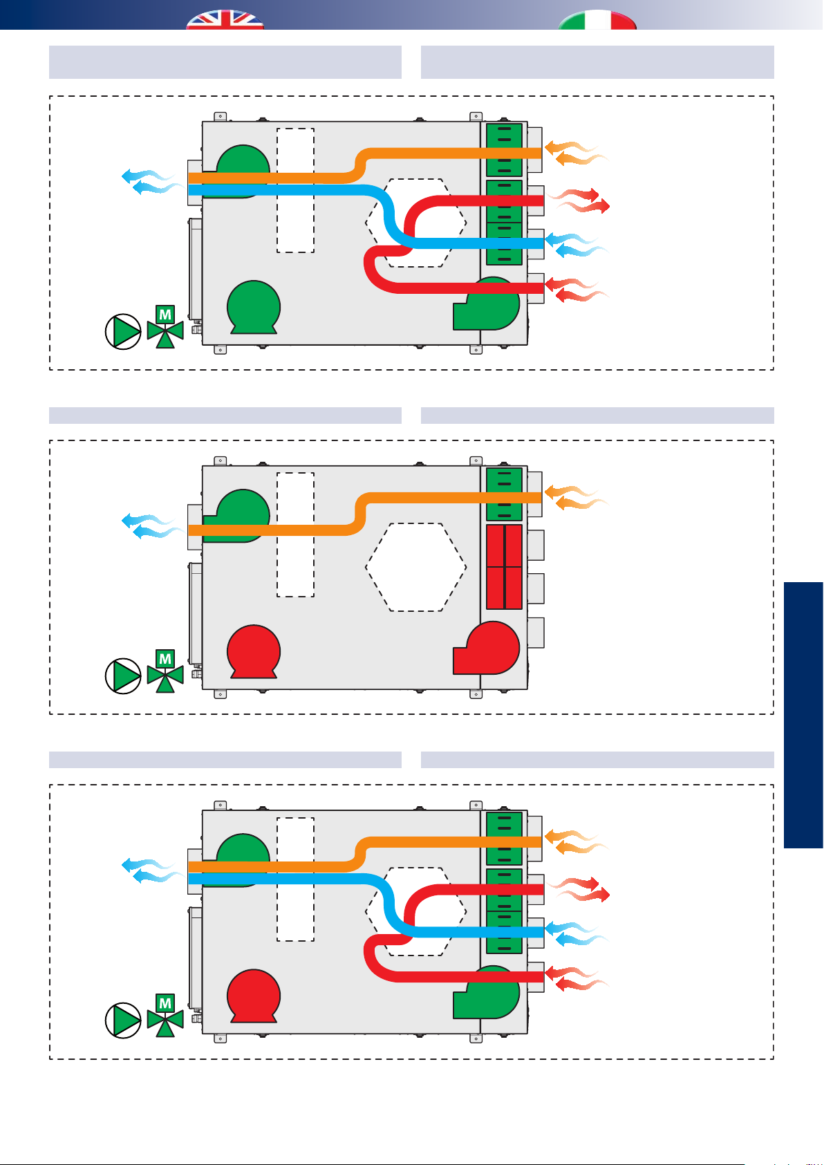
DEHUMIDIFICATION / SUMMER INTEGRATION
WITH AIR RENEWAL
DEUMIDIFICAZIONE / INTEGRAZIONE ESTIVA
CON RINNOVO
Supply to the rooms
Immissione ambienti
Supply to the rooms
Immissione ambienti
Finned pack
Pacco alettato
Heat exchanger
Recuperatore
di calore
INTEGRAZIONE INVERNALEWINTER INTEGRATION
Clean room intake
Ripresa da ambienti puliti
Exhaust
Espulsione
Outdoor air intake
Ripresa aria esterna
WC / Kitchen air intake
Ripresa WC / Cucina
Clean room air intake
Ripresa da ambienti puliti
Supply to the rooms
Immissione ambienti
Finned pack
Pacco alettato
Finned pack
Pacco alettato
Heat exchanger
Recuperatore
di calore
INTEGRAZIONE INVERNALE CON RINNOVOWINTER INTEGRATION WITH AIR RENEWAL
Heat exchanger
Recuperatore
di calore
USE
UTILIZZO
Clean room intake
Ripresa da ambienti puliti
Exhaust
Espulsione
Outdoor air intake
Ripresa aria esterna
WC / Kitchen air intake
Ripresa WC / Cucina
33
Page 34
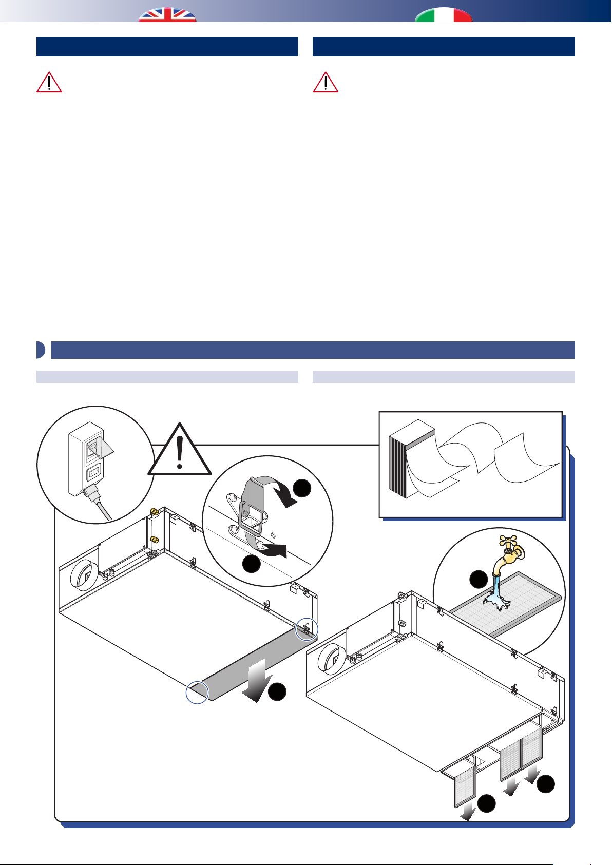
MAINTENANCE MANUTENZIONE
All the extraordinary maintenance operations
described in this chapter MUST ALWAYS BE CARRIED OUT BY
QUALIFIED PERSONNEL.
• Before performing any intervention on the unit or before
accessing internal parts, ensure that the electrical power
supply has been disconnected.
• There are moving components inside the unit. Take
particular care when operating in their vicinity, even when
the electrical power supply is disconnected.
• One part of the compressor casing and the delivery piping
are at a high temperature. Take particular care when
operating in their vicinity.
• Take particular care when operating in proximity to the
nned coils as the aluminium ns are particularly sharp.
• After maintenance operations, always close the unit using
the special panelling, securing it using xing screws.
1 - ORDINARY MAINTENANCE / MANUTENZIONE ORDINARIA
ORDINARY MAINTENANCE CLEANING THE FILTER MANUTENZIONE ORDINARIA PULIZIA FILTRO
Tutte le operazioni di manutenzione straordinaria
descritte in questo capitolo DEVONO ESSERE SEMPRE
ESEGUITE DA PERSONALE QUALIFICATO.
• Prima di effettuare qualsiasi intervento sull’unità o
prima di accedere a parti interne, assicurarsi di aver tolto
l’alimentazione elettrica.
• All’interno dell’unità sono presenti degli organi in
movimento. Prestare particolare attenzione quando
si operi nelle loro vicinanze anche ad alimentazione
elettrica disconnessa.
• Una parte dell’involucro del compressore e la tubazione
di mandata si trovano a temperatura elevata. Prestare
particolare attenzione quando si operi nelle loro
vicinanze.
• Prestare particolare attenzione quando si operi in
prossimità delle batterie alettate in quanto le alette di
alluminio risultano particolarmente taglienti.
• Dopo le operazioni di manutenzione richiudere sempre
l’unità tramite le apposite pannellature, ssandole con
le viti di serraggio.
OFF!
Spento!
29
30
1
2
3
every 30 days
ogni 30 giorni
6
28
Caution! The lter may be removed from any of the four
sides by removing the corresponding guide.
Attenzione! Il ltro può essere rimosso da qualunque
dei quattro lati rimuovendo la guida corrispondente.
4
5
34
Page 35
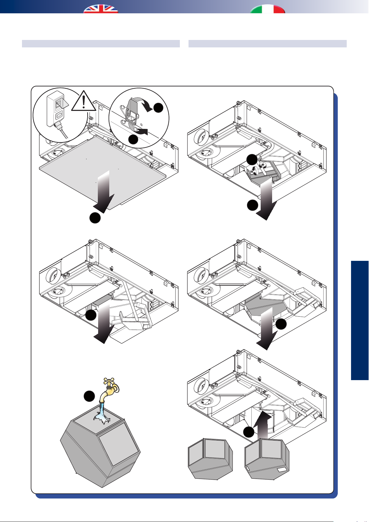
CLEANING THE EXCHANGER
PULIZIA SCAMBIATORE
Warning: the heat exchanger have to be cleaned every 5 years by
removing the bottom panel from the dehumidier.
1
Spento!
2
3
Attenzione! La pulizia dello scambiatore di calore va eettuata
ogni cinque anni e avviene rimuovendo il pannello inferiore
del deumifìdicatore.
4
5
6
7
USE
UTILIZZO
8
9
OKNO
35
Page 36
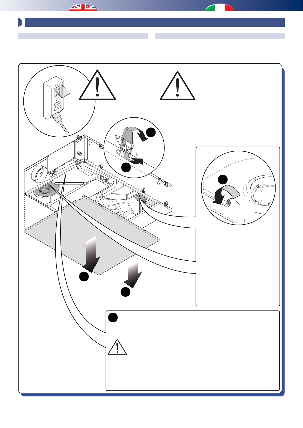
x 4
2 - EXTRAORDINARY MAINTENANCE / MANUTENZIONE STRAORDINARIA
REMOVING THE FAN
Caution! To replace the fan you must remove the lower dehumidier
panel.
OFF!
Spento!
2
RIMOZIONE VENTILATORE
Attenzione! La sostituzione del ventilatore avviene rimuovendo
il pannello inferiore del deumifìdicatore.
In order to replace the electric
fan condenser (at the side of
the motor), it is not necessary
to remove the fan.
Per la sostituzione del condensatore elettrico del ventilatore
(si trova a anco del motore)
non è necessario rimuovere il
ventilatore.
1
6
Finally remove the four screws (4)
which block the sides of the fan
case, lift it up slightly and slide it
out of the opening on the side of
the machine.
Rimuovere inne le quattro
3
4
Remove the fan power cable.
5
Rimuovere il cavo di alimentazione del ventilatore.
If operating from the bottom, it will not be possible to access the
whole path of the electrical cable, when it is removed, use a probe
to reposition the electrical cable of the new fan.
Se si opera dal basso verrà a mancare l’accesso all’intero
percorso del cavo elettrico, quindi quando viene slato prevedere una sonda per riposizionare il cavo elettrico del ventilatore nuovo.
viti(2) che bloccano lateralmente
la cassa del ventilatore, sollevarlo
leggermente e slarlo
dall’apertura presente sul anco
della macchina.
36
Page 37

ERRORS, ALARMS AND TROUBLESHOOTING
GUASTI, ALLARMI E POSSIBILI SOLUZIONI
NTC sensor failure:
Check if the wiring is correct, otherwise replace the sensor.
Pressure transducer failure:
Check if the wiring is correct, otherwise replace the transducer .
Failure with the dierential pressure transducer for fresh air
ventilation:
Check if the tubes become clogged, in this case remove the tubes
from the sensors and blow in. If you note some cracking in the
connection between the tubes and the board, replace the board
and the sensor.
Alarm for low pressure in the refrigerant circuit:
Run out of refrigerant gas. The unit shall be replaced.
In case of low latent load, this alarm can be caused by insucient
water ow rate.
Alarm for high pressure in the refrigerant circuit:
Incorrect air/water ow rate; or air/water temperature are too
high. Riset the unit parameters according to the values mentioned
in the manual.
Guasto sonde NTC:
Vericare che le sonde siano collegate correttamente, in caso
sostituire la sonda.
Guasto trasduttore di pressione:
Vericare che sia collegato correttamente, in caso sostituire il
trasduttore.
Guasto sensore di pressione dierenziale aria di rinnovo:
Vericare che non ci siano ostruzioni all’imbocco dei tubicini,
a tal proposito si consiglia di staccare i tubicini dai sensori
e provare a soare dentro, se invece si nota una cricca sul
collegamento tra i tubicini e la scheda o se il problema persiste
sostituire la schedina con i sensori.
Allarme bassa pressione circuito frigo:
La macchina è scarica di gas refrigerante, in questo caso bisogna
sostituire l’unità.
In casi di poco carico latente, potrebbe essere causato da
un’insuciente portata d’acqua refrigerata.
Allarma alta pressione circuito frigo:
Non sono garantite le corrette portate d’aria o di acqua, oppure
le temperature dell’aria o dell’acqua sono troppo elevate.
Riportare l’unità in un funzionamento all’interno dei limiti
imposti nel manuale.
Alarm for BUS connection:
Error in bus communication; check the wiring, you shall use a
shielded cable shorter than 50 m.
In case of disturbances use 120 termination resistance on both
ends.
Alarm for water temperature:
Water at a temperature above 25 °C.
Alarm for automatic restart.
Alarm for supply fan:
Check the right connection of the plugs, replace the processor
board, and if the problem persists replace the fan.
Alarm for exhaust fan:
Check the right connection of the plugs, replace the processor
board, and if the problem persists replace the fan.
Allarme comunicazione BUS:
Errore nella comunicazione BUS, verificare la corretta
realizzazione del collegamento, il cavo deve essere schermato
e di lunghezza non superiore ai 50 mt. In caso di disturbi
prevedere una resistenza da 120 su entrambi i capi dei cavi.
Allarme temperatura acqua:
Temperatura dell’acqua che ha superato i 25 °C.
Allarme a riarmo automatico.
Allarme ventilatore di immissione:
Vericare che gli spinotti siano collegati correttamente, provare
a sostituire la scheda processore, se il problema persiste,
sostituire il ventilatore
Allarme ventilatore di espulsione:
Vericare che gli spinotti siano collegati correttamente, provare
a sostituire la scheda processore, se il problema persiste,
sostituire il ventilatore.
37
DATI TECNICI
TECHNICAL DATA
Page 38

TECHNICAL DATA AND PERFORMANCE
1 - DIMENSIONS / DIMENSIONI
DATI TECNICI E PRESTAZIONI
7701178
275
Recirculation
Ricircolo
Discharge
Espulsione
Renewal
Rinnovo
WC/Kitchen intake
Ripresa wc/cuc
773
[mm]
Ø145
To the rooms
Agli ambienti
Ø145
Ø100
Ø100
Ø100
845,5
2 - TECHNICAL DATA / DATI TECNICI
Table of technical characteristics
Tabella delle caratteristiche tecniche
Technical specications Speciche tecniche
Condensation (26°C - 65% - 300m/h)
without external air
Condensation (26°C - 65% - 300m/h)
with external air (35°C - 50% - 160m/h)
Rated electrical power Potenza elettrica nominale W 590
Total max. power consumption of the fan Potenza elettrica max. assorbita dal ventilatore W 70
Power consumption on stand-by mode Consumo elettrico in stand-by W 5
Nominal air ow rate Portata aria nominale m/h 300
Nominal renewal air ow rate Portata aria nominale rinnovo m/h 160
Unit water ow rate Portata acqua unità l/h 400
Condensation water supply Attacchi alimentazione acqua F 1/2”
Pre-cooling water head loss Perdita di carico acqua pre-rareddamento DaPa 799
Refrigerant (R 134A) Refrigerante (R 134A) gr 0,570
Overall machine dimensions Ingombri della macchina
Height Altezza mm 275
Width (without hidraulic connection) Larghezza (senza attacchi idraulici) mm 800
Depth Profondità mm 1178
Weight Peso kg 55
Machine packaging Imballi macchina
Height Altezza mm 400
Width Larghezza mm 900
Depth Profondità mm 1250
Umidità condensata (26°C - 65% - 300m/h)
esclusa aria esterna
Umidità condensata (26°C - 65% - 300m/h)
compresa aria esterna (35°C - 50% - 160m/h)
38
l/day
l/giorno
l/day
l/giorno
38,7
51,4
Page 39
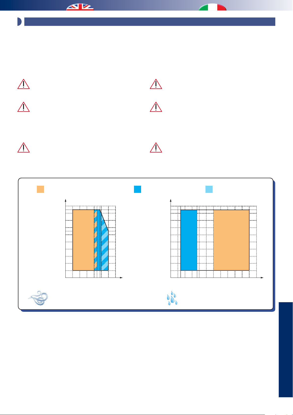
3 - OPERATING LIMITS / LIMITI DI FUNZIONAMENTO
The graphs shown below describe the operating range of the unit.
The maximum permitted temperature of the water for operation
in summer mode is 18 °C.
Above 25°C, the compressor is excluded, leaving only the fan
running.
Between 30 and 55 °C it is possible to activate the ventilation mode
only for use of the appliance in winter.
With water temperatures higher than 55°C, the
appliance could be damaged.
It is important to ensure that the units operate within
the limits shown. Beyond these limits, normal operation is
not guaranteed, nor is the reliability and integrity of the
units (for special applications, contact the manufacturers
technical oce).
While the unit is working in fresh air ventilation mode
with outdoor temperature below -5 °C, the heat exchanger
can freeze; it is recommended to use a safety thermostat to
interrupt the operation.
I graci sottoriportati descrivono il campo operativo dell’unità. La
massima temperatura dell’acqua ammessa nel funzionamento
estivo è di 18 °C.
Al di sopra di 25°C, il compressore viene escluso, lasciando
in funzione solamente il ventilatore. Tra i 30 e 55 °C è
possibile attivare la sola ventilazione per un uso invernale
dell’apparecchio.
Con temperature dell’acqua superiori a 55°C
l’apparecchio potrebbe danneggiarsi.
È importante fare in modo che le unità operino nei
limiti riportati. Al di fuori di tali limiti non sono garantiti
né il normale funzionamento né tantomeno l’adabilità
e l’integrità delle unità (per applicazioni particolari
contattare l’ucio tecnico del Costruttore).
In funzionamento Rinnovo, con temperature
esterne inferiori a -5 °C il recuperatore potrebbe gelare, si
consiglia quindi di prevedere un termostato di sicurezza
per intercettare la funzionalità.
Winter integration / free-cooling
Integrazione invernale / free-cooling
100
24
95
90
80
70
65
60
50
40
30
Umidità relativa
Relative humidity
20
10
22
15100 20 25 30 35
5
Air intake temperature to the coil [°C ]
Temperatura ingresso aria alle batterie [°C ]
Dehumidication
Deumidicazione
100
95
90
80
70
60
50
40
30
Umidità relativa
Relative humidity
20
10
0 3010 20 40 50 60
Summer integration
Integrazione estiva
7
18 55
Water intake temperature [°C ]
Temperatura ingresso acqua [°C ]
39
DATI TECNICI
TECHNICAL DATA
Page 40

0.6
10
Power to be supplied [kW]
Tambiente - Taria prima batterie [°C]
Taria prima batterie - Tambiente [°C]
4 - OPERATION IN VENTILATION MODE ONLY / FUNZIONAMENTO IN SOLA VENTILAZIONE
If the unit is requested to run the renewal or boost function, it is
necessary to provide the machine using a certain amount of power
from the hydronic circuit to make the neutral air exit the unit. The
required amount of power is reported in the graph below.
Summer
Estate
0.5
0.4
0.3
0.2
Potenza da fornire [kW]
Nel caso in cui all’unità venga richiesta la funzione di rinnovo
o boost, si rende necessario dover fornire alla macchina una
certa quantità di potenza tramite il circuito idronico per far
uscire aria neutra dall’unità. La potenza necessaria è ricavabile
dal graco sottostante.
Winter
Inverno
80 m/h
120 m/h
160 m/h
0.1
0
012345678910 0123456789
Troom - Tair before coils [°C]
5 - SUMMER PERFORMANCE / PRESTAZIONI ESTIVE
Yield during dehumidication, depending on room temperature,
relative humidity, considering a unit supplied with water at 15°C.
Performance in recirculation mode
Resa in ricircolo
Inlet air
Aria in ingresso
° C % UR ° C % UR W l/g °C W W W W
26,0 55 26 35 734 25.4 10.0 1118 490 1234 1724
26,0 65 26 37 1030 35.6 10.9 1060 490 1530 2020
26,0 55 26 41.6 735 25.4 12.6 1407 735 1255 1990
26,0 65 26 44.8 1120 38.7 13.7 1289 735 1640 2375
Outlet air
Aria in uscita
Latent cooling
power
Pot. frig. latente
Tair before coils - Troom [°C]
Resa in deumidificazione, in funzione della temperatura
ambiente, umidità relativa considerando l’unità alimentata
con acqua a 15°C.
Min. inow
air temp
Minima
temp. aria
di mandata
200 m/h
300 m/h
Sens. cooling
power
Pot. frig. sensibile
Max Set 19 °C
Cooling power to be supplied
to the unit
Potenza frigorifera da
fornire all’unità
Dehumidic.
Deumidicaz.
Integration*
Integrazione*
40
Page 41

Performance in recirculation mode + renewal mode
Resa in ricircolo + rinnovo
Neutral
Recirculation air
Aria di ricircolo
° C % UR m/h ° C % UR m/h ° C % UR kW l/g °C W W W W
26,0 55 120 35 50 80 26 37.3 1.07 37.0 11.0 1049 490 1572 2062
26,0 65 120 35 50 80 26 38.5 1.25 43.1 11.5 1015 490 1747 2237
26,0 55 40 35 50 160 26 39.9 1.40 39.9 12.0 978 490 1901 2391
26,0 65 40 35 50 160 26 40.5 1.46 50.4 12.2 964 490 1961 2451
26,0 55 220 35 50 80 26 44.2 1.02 35.3 13.5 1311 735 1541 2276
26,0 65 220 35 50 80 26 46.4 1.31 45.1 14.3 1230 735 1826 2561
26,0 55 140 35 50 160 26 46.7 1.31 45.3 14.4 1221 735 1832 2567
26,0 65 140 35 50 160 26 48.3 1.49 51.4 14.9 1167 735 2008 2743
Renewal air
Aria di rinnovo
outlet air
Aria
neutra in
uscita
Latent
cooling
power
Pot. frig.
latente
200 m/h
300 m/h
Min. inow
air temp
Minima
temp. aria
di mandata
Sens. cooling
power
Pot. frig.
sensibile
Max
Set 19 °C
Cooling power to be
supplied to the unit
Potenza frigorifera da
fornire all’unità
Dehumidic.
Deumidicaz.
Integration*
Integrazione*
* The power to give to the integration unit has to be intended as
the necessary power on the default set-point, for dierent value
the power has to be veried
* La potenza da fornire all’unità in integrazione è da intendersi
come la potenza necessaria per il valore di set-point di
fabbrica, per valori diversi la potenza da fornire dovrà essere
rivericata.
Performance in renewal mode**
Resa in rinnovo**
Min. inow
Inlet air
Aria in ingresso
° C % UR ° C % UR W l/g °C W W W W
30 50 26 32.3 910 31,4 8.8 964 392 1397 1789
33 50 26 34.1 1201 41,5 9.6 918 392 1688 2080
35 50 26 35.7 1416 48,9 10.3 880 392 1903 2295
* The power to give to the integration unit has to be intended as
the necessary power on the default set-point, for dierent value
the power has to be veried
** Renewal function is allowed only if the intake fan and the
expulsion fan are working with the same ow rate of 160 m3/h,
to calculate the air temperature after the heat recovery unit is
supposed a room temperature of 26°C.
Outlet air
Aria in uscita
Latent cooling
power
Pot. frig. latente
air temp
Minima
temp. aria
di mandata
* La potenza da fornire all’unità in integrazione è da intendersi
** Il funzionamento in solo rinnovo è previsto solamente
Sens. cooling power
Pot. frig. sensibile
Max Set 19 °C
come la potenza necessaria per il valore di set-point di
fabbrica, per valori diversi la potenza da fornire dovrà essere
rivericata.
nell’unico caso in cui Ventilatore di immissione e ventilatore
di espulsione lavorano alle stesse portate ovvero 160 m/h;
è stata ipotizzata inoltre la temperatura ambiente di 26°C
per i calcolo della temperatura dell’aria dopo il recuperatore.
Cooling power to be supplied
to the unit
Potenza frigorifera da
fornire all’unità
Dehumidic.
Deumidicaz.
Integrazione*
Integration*
41
DATI TECNICI
TECHNICAL DATA
Page 42
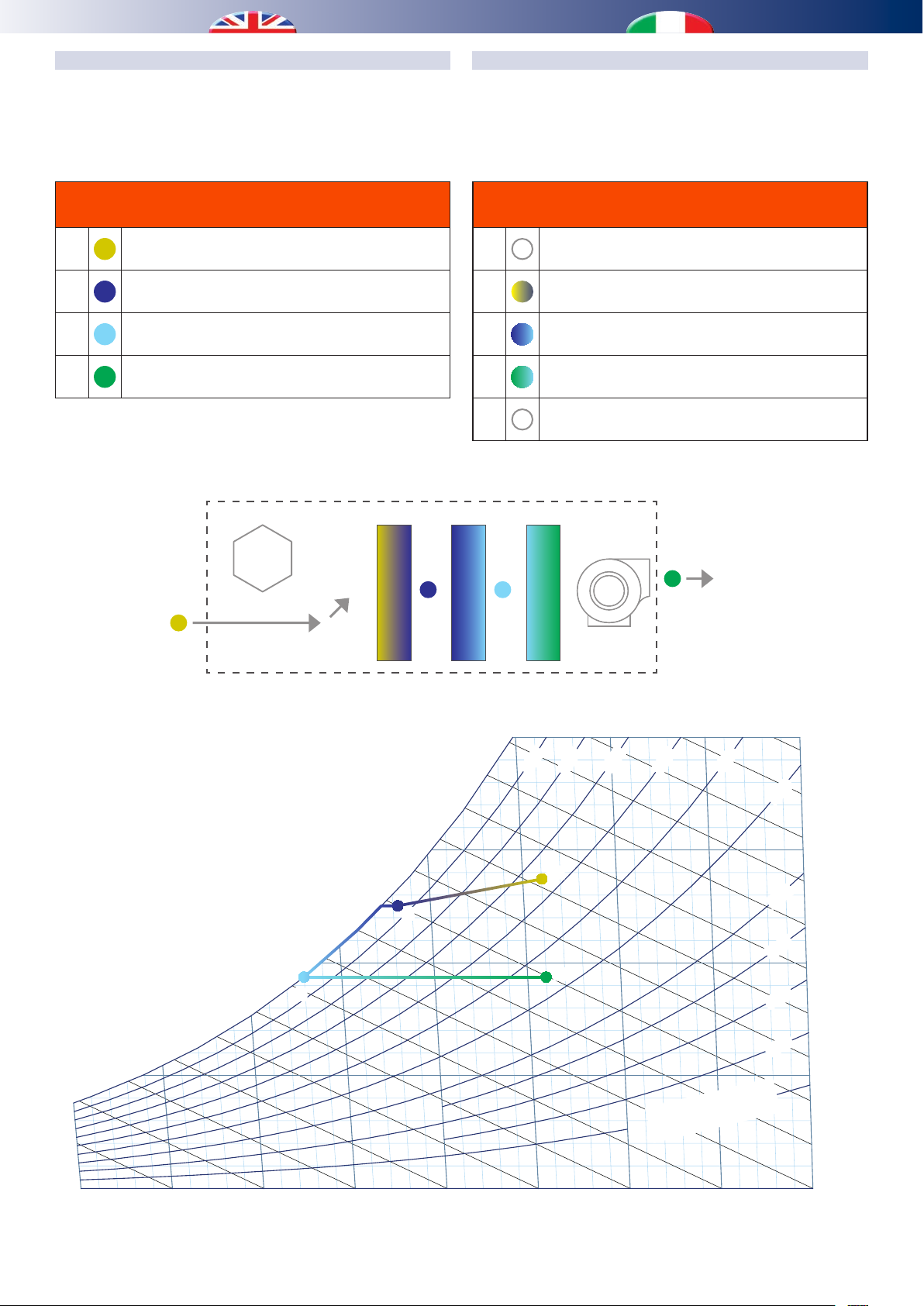
Temperatura Bulbo Umido - (°C)
Umidità Specica - (g vapore/Kg a.s.)
Psychometric diagram - Diagramma Psicrometrico
Air ow diagram - Schema Flusso Aria
EXAMPLE OF RECIRCULATION PERFORMANCE
ESEMPIO PRESTAZIONE RICIRCOLO
Yield during dehumidication in recirculation mode, with a ow
rate of 300 m3/h, with a unit supplied with water at a temperature
of 15 °C, with room delivery air at 26° and a R.H. of 65% and later
delivered back into the room at 26° and R.H. of 44.8%.
Air key
Legenda aria
Ai
C
D
E
Room air intake
Ripresa aria ambiente
Pre-treatment post-coil
Post batteria Pre-Trattamento
Evaporator post-coil
Post batteria Evaporante
Room air delivery
Immissione aria ambiente
1234
Resa in deumidicazione in modalità ricircolo con portata di 300
m3/h, unità alimentata con acqua a 15 °C, Ripresa Aria ambiente
a 26° e 65% U.R. e successiva re-immissione in ambiente a 26°
e 44.8% U.R.
Parts key
Legenda componenti
1
2
3
4
5
Recovery unit
Recuperatore
Pre-treatment coil
Batteria Pre-Trattamento
Evaporator coil
Batteria Evaporante
Condenser coil
Batteria Condensante
Delivery fan
Ventilatore Immissione
5
Ai
45
Enthalpy - (Kj/Kg a.s.)
30
25
20
15
10
5
40
Entalpia - (Kl/Kg a.s.)
35
D
50
55
C
65
60
C
70
75
D
80
80%
70%
90%
Ai
E
E
90
60%
10% relative humidity
10% Umidità Relativa
50%
20
40%
15
30%
25%
10
20%
15%
Specic humidity (g vapour /kg a/s)
5
0510 15 20 25 30 35 40
Wet bulb temperature - (°C)
42
Page 43

EXAMPLE OF RENEWAL PERFORMANCE
Temperatura Bulbo Umido - (°C)
Umidità Specica - (g vapore/Kg a.s.)
Psychometric diagram - Diagramma Psicrometric
A
ir ow diagram - Schema Flusso Aria
ESEMPIO PRESTAZIONE RINNOVO
Yield during dehumidication in renewal mode, with a ow rate
of 160 m3/h, with a unit supplied with water at a temperature of
15 °C, with outdoor air delivery at 35° and a R.H. of 50% and later
delivered back into the room at 26° and R.H. of 35.7%.
Air key
Legenda aria
Ae1
Ae2
C
D
E
Outdoor Air Intake
Ingresso aria esterna
Post Recovery Unit Outdoor Air
Aria Esterna Post Recuperatore
Pre-Treatment Post-Coil
Post Batteria Pre-Trattamento
Evaporator Post-Coil
Post Batteria Evaporante
Room Air Delivery
Immissione Aria ambiente
Resa in deumidicazione in modalità rinnovo con portata di
160 m3/h, unità alimentata con acqua a 15 °C, Ingresso Aria
Esterna a 35° e 50% U.R. e successiva Immissione in ambiente
a 26° e 35.7% U.R.
Parts key
Legenda componenti
1
2
3
4
5
1234
Recovery unit
Recuperatore
Pre-treatment coil
Batteria Pre-Trattamento
Evaporator coil
Batteria Evaporante
Condenser coil
Batteria Condensante
Delivery fan
Ventilatore Immissione
5
Ae1
Ae2
45
Enthalpy - (Kj/Kg a.s.)
30
25
D
20
15
10
5
0510 15 20 25 30 35 40
40
Entalpia - (Kl/Kg a.s.)
35
C
D
o
75
70
65
60
55
50
C
Wet bulb temperature - (°C)
90%
E
80
80%
Ae2
90
70%
60%
10% relative humidity
10% Umidità Relativa
E
20
50%
Ae1
40%
15
30%
25%
10
20%
15%
Specic humidity (g vapour /kg a/s)
5
DATI TECNICI
TECHNICAL DATA
43
Page 44

Temperatura Bulbo Umido - (°C)
Umidità Specica - (g vapore/Kg a.s.)
Psychometric diagram - Diagramma Psicrometrico
A
ir ow diagram - Schema Flusso Aria
EXAMPLE OF RECIRCULATION + RENEWAL PERFORMANCE
ESEMPIO PRESTAZIONE RICIRCOLO + RINNOVO
Yield during dehumidication in recirculation + renewal mode
with a total ow rate of 300 m3/h, when the unit is supplied with
water at a temperature of 15 °C. Recirculation 140 m3/h Room air
at 26° and R.H. of 65 + Renewal 160 m3/h outdoor air at 35° and
R.H. 50%, with later mixing and re-delivery into the room at 26°
and R.H. of 48.3%
Air key
Legenda aria
Ae1
Ae2
Ai
B
Outdoor Air Intake
Ingresso aria esterna
Post Recovery Unit Outdoor Air
Aria Esterna Post Recuperatore
Room air intake
Ripresa Aria Ambiente
Ae2-Ai Mixed Air
Aria Miscelata Ae2-Ai
Resa in deumidicazione in modalità ricircolo + rinnovo con
portata totale di 300 m3/h, unità alimentata con acqua a 15 °C.
Ricircolo 140 m3/h Aria ambiente a 26° e 65 U.R. + Rinnovo 160
m3/h Aria Esterna a 35° e 50% U.R., con successiva miscelazione
e re-immissione in ambiente a 26° e 48.3% U.R.
C
D
E
1234
Pre-Treatment Post-Coil
Post Batteria Pre-Trattamento
Evaporator Post-Coil
Post Batteria Evaporante
Room Air Delivery
Immissione Aria ambiente
Parts key
Legenda componenti
1
2
3
4
5
5
Recovery unit
Recuperatore
Pre-treatment coil
Batteria Pre-Trattamento
Evaporator coil
Batteria Evaporante
Condenser coil
Batteria Condensante
Delivery fan
Ventilatore Immissione
Ae1
Ai
Ae2
45
Enthalpy - (Kj/Kg a.s.)
30
25
20
15
10
5
40
Entalpia - (Kl/Kg a.s.)
35
D
B
50
C
65
60
55
C
70
75
D
80
80%
Ae2
B
70%
90%
Ai
E
E
90
60%
10% relative humidity
10% Umidità Relativa
50%
Ae1
20
40%
15
30%
25%
10
20%
15%
Specic humidity (g vapour /kg a/s)
5
0510 15 20 25 30 35 40
Wet bulb temperature - (°C)
44
Page 45

3,5
30
Power [kW]
Delta Temperatura [K]
6 - OPERATION IN WINTER INTEGRATION MODE / FUNZIONAMENTO INTEGRAZIONE INVERNALE
If the winter integration function is enabled, the unit will start the
delivery fan (if renewal is enabled then the output fan will also
start). Integration can be managed in two ways:
- Controlled-power integration (from set-point)
The unit will automatically adjust the ow rate through a 2-way
motorized valve (with an optional 0-10 V servomotor) installed
upstream, to obtain a temperature value that is equal to the
integration set-point, as set on the control unit panel.
- Total power integration
The unit will be hydraulically supplied at the pre-set nominal ow
rate and will deliver the maximum available power into the room.
From the graphs below it is possible to nd the powers that need
to be delivered and supplied by the unit in both congurations.
CONTROLLEDPOWER INTEGRATION GRAPH
300 m/h
3
240 m/h
160 m/h
Se viene attivata la funzione di integrazione invernale, l’unità
attiva il ventilatore di immissione (in caso di rinnovo anche il
ventilatore di espulsione). La gestione dell’integrazione può
essere eettuata in due modi:
- Integrazione a potenza controllata (da set-point)
L’unità andrà ad autoregolare la portata, tramite la valvola 2 vie
con servomotore 0-10V (opzionale) posta a monte, in modo da
ottenere in uscita un valore di temperatura pari al set-point di
integrazione impostato nella centralina di controllo.
- Integrazione con totale potenza
L’unità viene alimentata idraulicamente alla portata nominale
pre-impostata e immette in ambiente la massima potenza
disponibile.
Nei grafici seguenti, è possibile ricavare le varie potenze
immesse e da fornire all’unità, in entrambe le congurazioni.
GRAFICO INTEGRAZIONE A POTENZA CONTROLLATA
2,5
2
1,45
1,5
Potenza [kW]
1,1
1
0,5
0
0510 15 20 25
Example
Air ow rate: 200 m3/h
Setpoint Temperature 35 °C
Room temperature:20°C
Air temperature at coil input 15°C
80 m/h
Temperature dierence [K]
Esempio
Portata aria: 200 m/h
Temperatura Setpoint : 35 °C
Temperatura ambiente : 20°C
Temperatura aria all’ingresso delle batterie : 15°C
Temperature delta with room 15°K
Power delivered into the room: 1.1 kW
Temperature delta with Air before coils: 20°K
Power to be supplied to the unit: 1.45 kW
Delta temperatura con ambiente 15°K
Potenza immessa in ambiente: 1,1 kW
Delta temperatura con Aria prima batterie: 20 °K
Potenza da fornire all’unità: 1,45 kW
45
DATI TECNICI
TECHNICAL DATA
Page 46
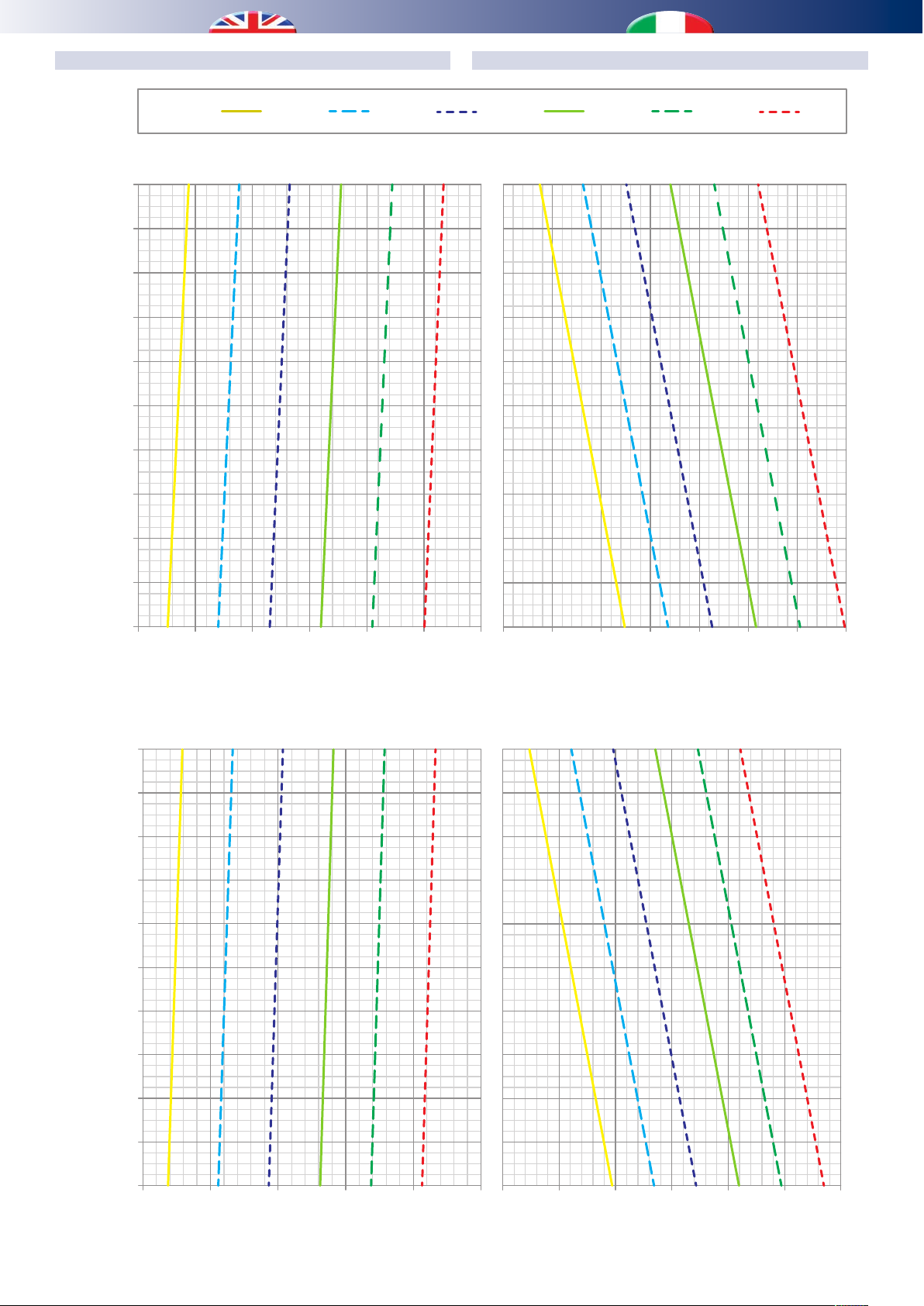
GRAFICI INTEGRAZIONE A TOTALE POTENZATOTAL POWER INTEGRATION GRAPHS
Tair before coil [°C]
54
Potenza resa [kW] Potenza da fornire all’unità [kW]
Tair before coil [°C]
3,5
Potenza resa [kW] Potenza da fornire all’unità [kW]
Air ow rate 240 m3/h
20
19
18
17
16
15
14
Taria prima batterie [°C]
13
12
Twater
Tacqua
30 °C
35 °C
40 °C 45 °C 50 °C
Air ow rate 300 m/h
Portata aria 300 m/h
55 °C
11
10
0,511,522,5 33,5
Heating power [kW]
Portata aria 240 m3/h
20
19
18
17
16
15
14
0,511,522,533,
Heating power to be supply to the unit [kW]
Taria prima batterie [°C]
13
12
11
10
0,511,522,5 3
Heating power [kW]
0,511,522,53
Heating power to be supply to the unit [kW]
46
Page 47
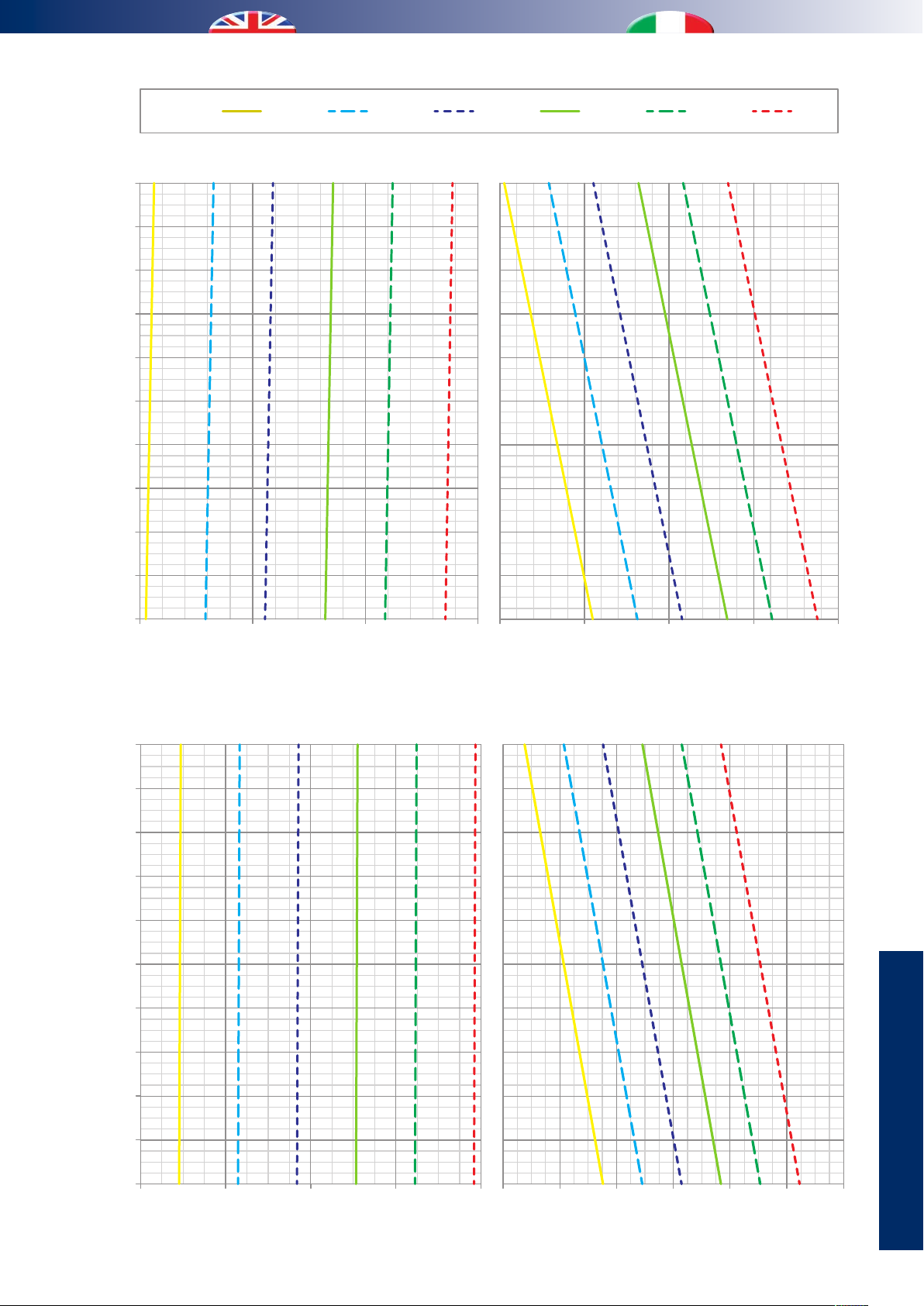
20
Tair before coil [°C]
2,5
Potenza resa [kW] Potenza da fornire all’unità [kW]
Tair before coil [°C]
Potenza resa [kW] Potenza da fornire all’unità [kW]
Air ow rate 80 m3/h
4
19
18
17
16
15
14
Taria prima batterie [°C]
13
12
Twater
Tacqua
30 °C
35 °C
40 °C 45 °C 50 °C
Air ow rate 160 m3/h
Portata aria 160 m3/h
55 °C
11
10
0,511,52
Heating power [kW]
Portata aria 80 m3/h
20
19
18
17
16
15
14
0,511,52
Heating power to be supply to the unit [kW]
Taria prima batterie [°C]
13
12
11
10
0,20,4 0,60,8 1
Heating power [kW] Heating power to be supply to the unit [kW]
0,20,4 0,60,811,2 1,
47
DATI TECNICI
TECHNICAL DATA
Page 48
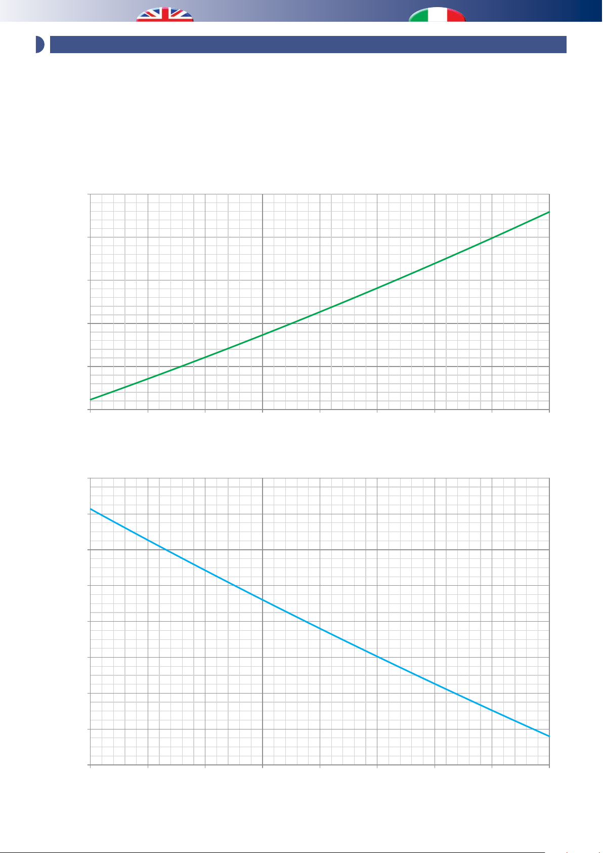
0
Eciency [%]
Portata aria rinnovo [m3/h]
Summer season
80
80 90 100110 120130 140150 160
Pressure drop [Pa]
7 - RECOVERY UNIT PERFORMANCE / PRESTAZIONI RECUPERATORE
The heat recovery unit is of high efficiency type (~90%). The
performance, however, must not be considered xed. It can vary
according to various factors: air ow rate, outdoor temperature and
relative humidity (the last two factors only apply to winter mode).
Several graphs are provided below, which group together various
possible solutions, and can be used to nd a more exact eciency
value.
70
60
50
Perdita di carico [Pa]
Il recuperatore di calore dell’unità è del tipo ad alta ecienza
~90%. Le prestazioni però, non sono da considerarsi sse,
possono variare secondo diversi fattori: portate dell’aria,
temperatura esterna e umidità ambiente (per le ultime due
solo nel caso invernale).
Qui di seguito vengono riportati più grafici, realizzati
raggruppando più soluzioni possibili, da cui poter ricavare un
valore di ecienza più preciso.
40
30
93
92
91
90
89
Ecienza [%]
88
Stagione estiva
87
86
85
80 90 100110 120130 140150 16
Renewal air ow rate [m3/h]
48
Page 49
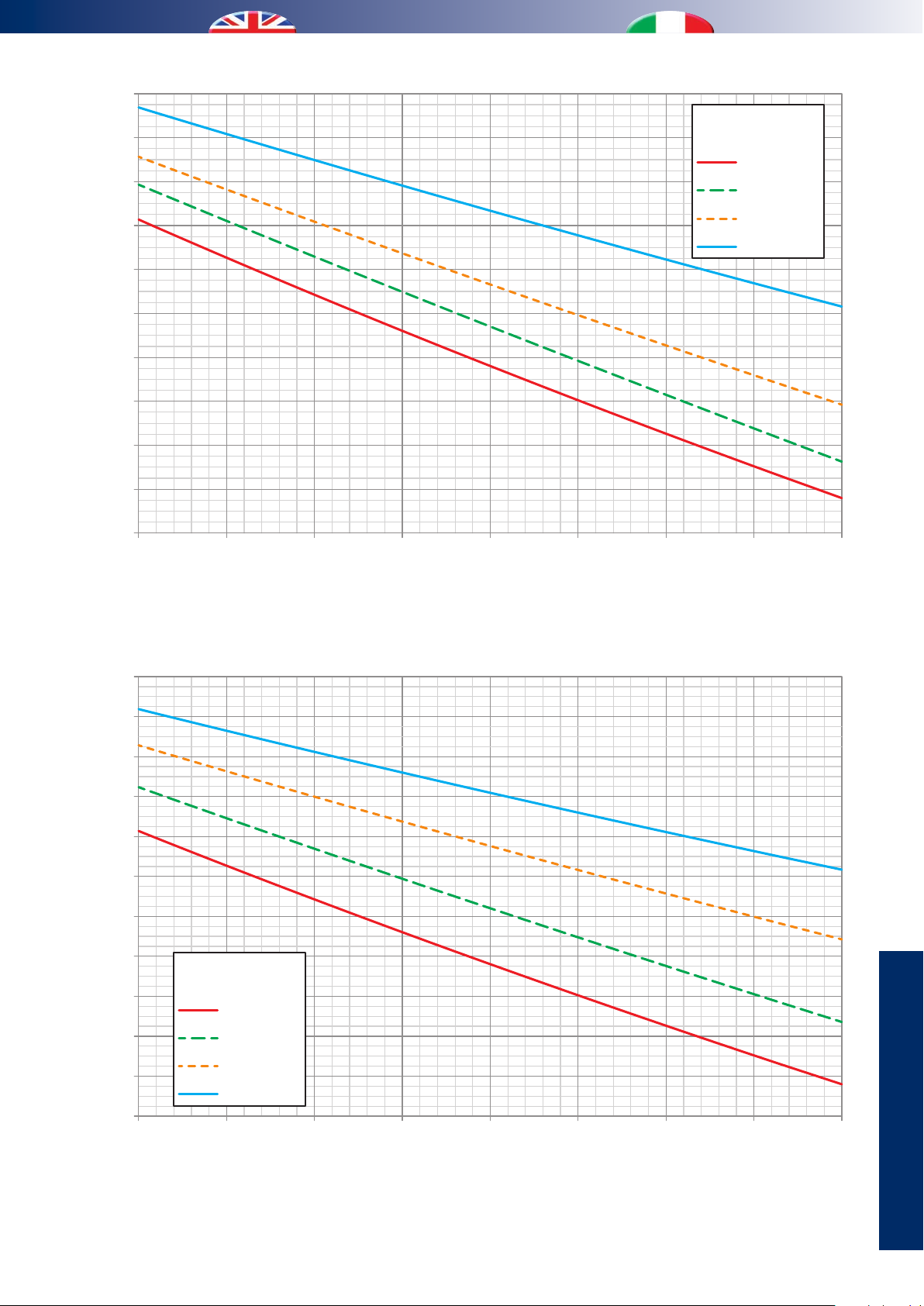
95
0
Eciency [%]
Portata aria rinnovo [m3/h]
External temperature 0 °C
0
Eciency [%]
Portata aria rinnovo [m3/h]
External temperature -5 °C
94
93
Temperatura esterna 0 °C
Room H.R.
U.R. ambiente
DRY / < 32%
35%
92
91
90
Ecienza [%]
89
88
87
86
85
80 90 100110 120130 140150 16
Renewal air ow rate [m3/h]
96
Temperatura esterna -5 °C
40%
50%
95
94
93
92
91
90
Ecienza [%]
89
88
87
86
85
80 90 100110 120130 140150 16
Room H.R.
U.R. ambiente
DRY / < 25%
30%
40%
50%
Renewal air ow rate [m3/h]
DATI TECNICI
TECHNICAL DATA
49
Page 50
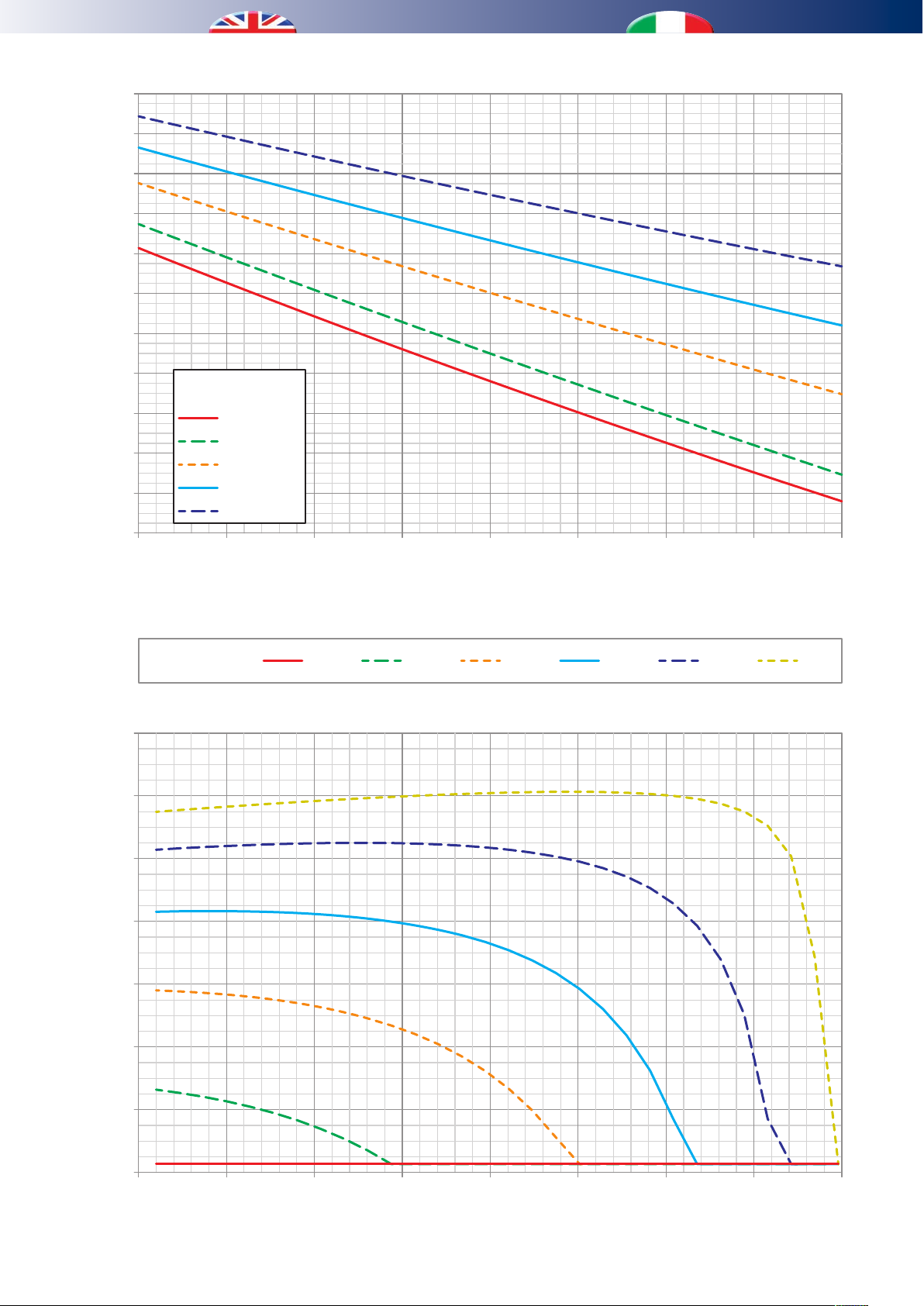
96
0
Eciency [%]
Portata aria rinnovo [m3/h]
External temperature -10 °C
520
Eciency [%]
Temperatura esterna [°C]
95
94
93
92
91
90
Ecienza [%]
89
88
87
86
85
80 90 100110 120130 140150 16
Room H.R.
U.R. ambiente
DRY / < 18%
20%
30%
40%
50%
Temperatura esterna -10 °C
Renewal air ow rate [m3/h]
Room R.H.
U.R. ambiente
99
98
97
96
95
Ecienza [%]
94
20%DRY 40% 60% 80%
Renewal air ow rate 80 m3/h
Portata aria rinnovo 80 m3/h
95%
93
92
-20-15 -10-50 5101
External temperature [°C]
50
Page 51
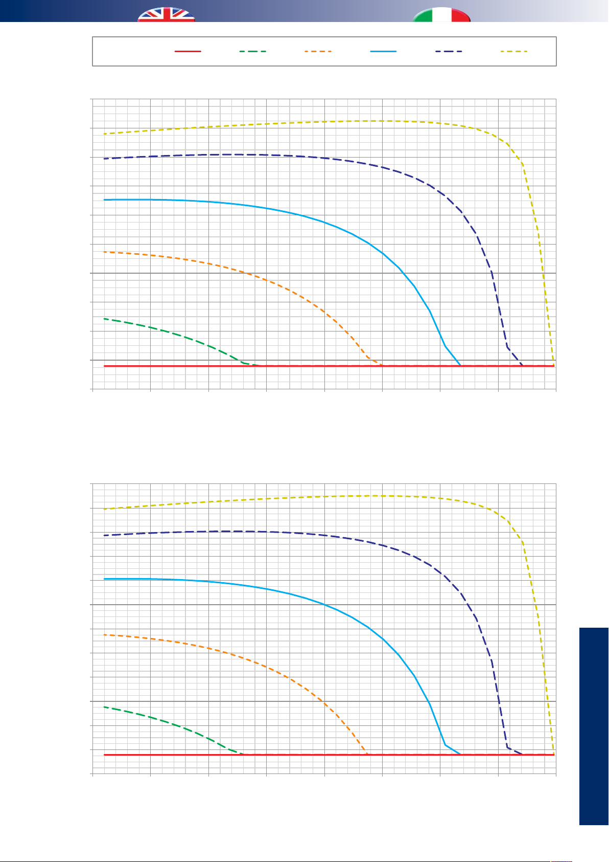
520
Eciency [%]
Temperatura esterna [°C]
Room R.H.
520
Eciency [%]
Renewal air ow rate 160 m3/h
Temperatura esterna [°C]
U.R. ambiente
98
97
96
95
94
93
Ecienza [%]
92
91
90
20%DRY 40% 60% 80%
Renewal air ow rate 120 m3/h
Portata aria rinnovo 120 m3/h
95%
89
88
-20-15 -10-50 5101
External temperature [°C]
97
96
95
94
93
92
91
90
Ecienza [%]
Portata aria rinnovo 160 m3/h
89
88
87
86
85
-20-15 -10-50 5101
External temperature [°C]
51
DATI TECNICI
TECHNICAL DATA
Page 52
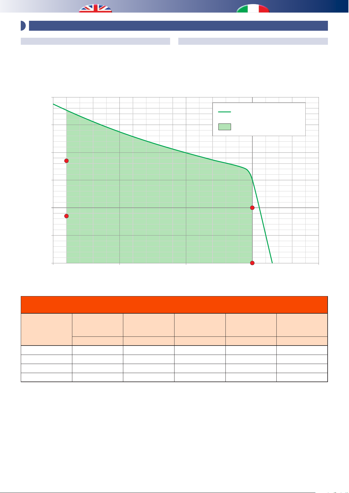
300
Portata aria [m3/h]
0350
Performance on recirculation mode [Pa]
8 - FAN PERFORMANCE / PRESTAZIONI VENTILATORI
INFLOW FAN
The performance must be considered net of the recirculation
function; with the renewal function it is necessary to subtract any
losses caused by the heat recovery unit from the performance,
based on the ow rates in the design (see relative graph)
250
200
2
150
100
1
Prevalenza utile totale ricircolo [Pa]
VENTILATORE DI IMMISSIONE
Le prestazioni sono da considerarsi al netto del funzionamento
in ricircolo; nel caso di funzionamento combinato con rinnovo,
si rende necessario dover sottrarre dalle performance, le perdite
dovute al recuperatore di calore in base alle portate di progetto
(vedere relativo graco).
MAX speed
Velocità MAX
Operating range
Range di funzionamento
4
50
0
150200 250
Air owrate [m
Chart for the output sound performance in the supply fan
Tabella prestazioni acustiche in uscita al ventilatore di immissione
Point
Punto
Flow rate
Portata
m3/h Pa dB(A) dB(A) dB(A)
1 160 85 48.0 37.0 27.5
2 160 185 53.5 42.9 33.5
3 300 0 54.4 43.4 33.9
4 300 100 56.0 45.0 35.5
N.B. Sound values collected through lab testing in
reverberation room.
Performance
Prevalenza
Sound power
Potenza sonora
N.B. Valori acustici rilevati da test di laboratorio eettuati
in camera riverberante.
3
/h]
3
30
Sound pressure
Pressione sonora
1 m
Sound pressure
Pressione sonora
3 m
52
Page 53
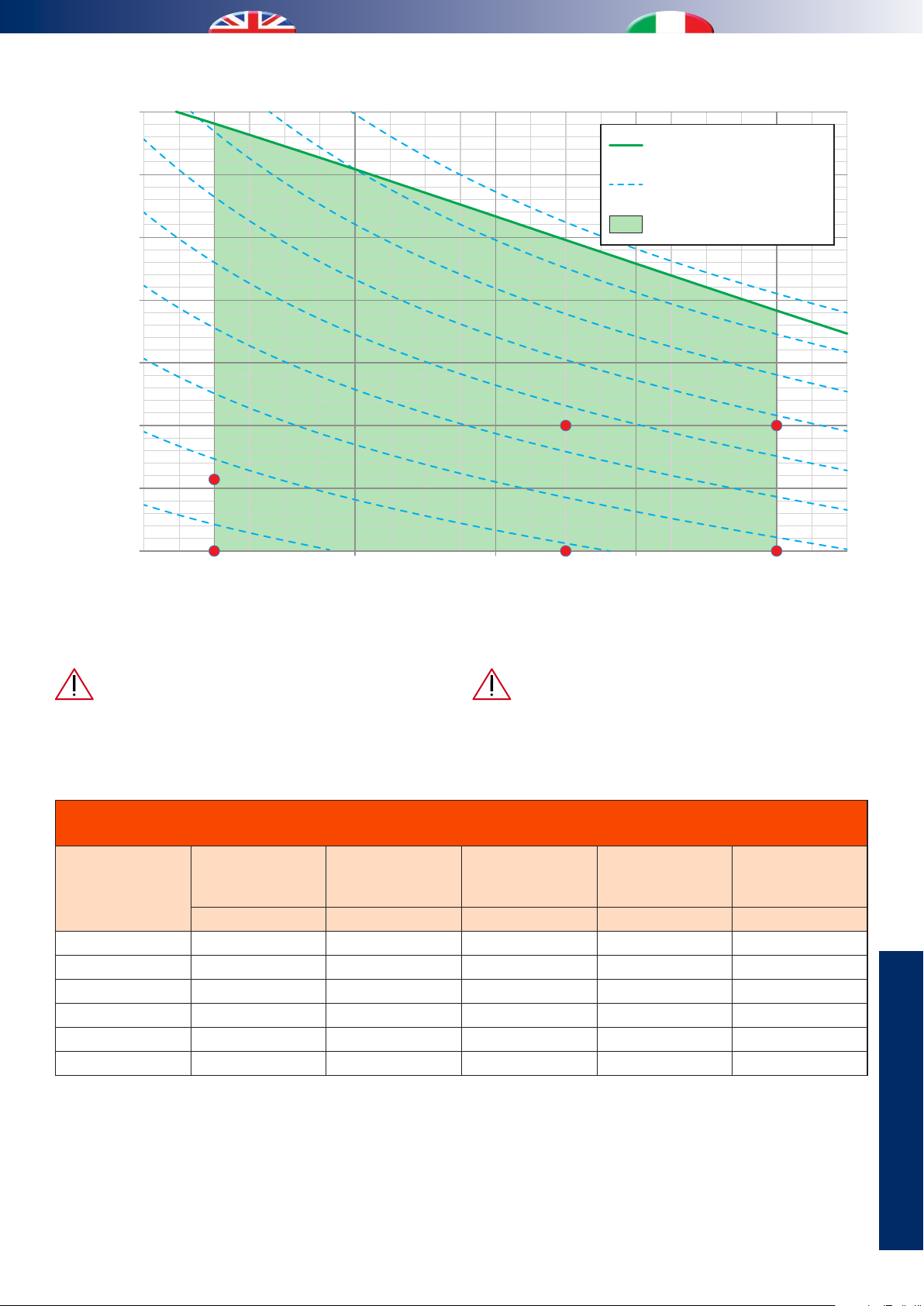
300
350
Portata aria [m3/h]
Performance on air renewal mode [Pa]
250
200
150
35 W
30 W
25 W
20 W
45 W
50 W
MAX speed
Velocità MAX
Power consumption
Consumo elettrico
Operating range
Range di funzionamento
15 W
100
Prevalenza utile totale rinnovo [Pa]
50
10 W
0
Energy consumption only refers to the supply fan. Total
energy calculation shall include the power of the exhaust fan,
can be gured out in the graph on the following page.
Chart for the output sound performance in the supply fan
2
1
80
100
120 140 160
Air owrate [m3/h]
N.B. Consumi elettrici ricavati da test di laboratorio.N.B. Power consumption measured during laboratory tests.
immissione per il calcolo energetico bisogna sommare
la potenza del ventilatore di espulsione, ricavabili nella
pagina successiva.
Tabella prestazioni acustiche in uscita al ventilatore di immissione
Point
Punto
1 80 0 37.5 26.5 17.0
2 80 57 43.7 32.7 23.2
3 130 0 43.6 32.6 23.1
4 130 100 51.4 40.4 30.9
5 160 0 48.0 37.0 27.5
6 160 100 53.9 42.9 33.4
Flow rate
Portata
m3/h Pa dB(A) dB(A) dB(A)
Performance
Prevalenza
Sound power
Potenza sonora
4
3
I consumi elettrici sono del solo ventilatore di
Sound pressure
Pressione sonora
1 m
6
5
Sound pressure
Pressione sonora
3 m
N.B. Sound values collected through lab testing in
reverberation room.
N.B. Valori acustici rilevati da test di laboratorio eettuati
in camera riverberante.
DATI TECNICI
TECHNICAL DATA
53
Page 54
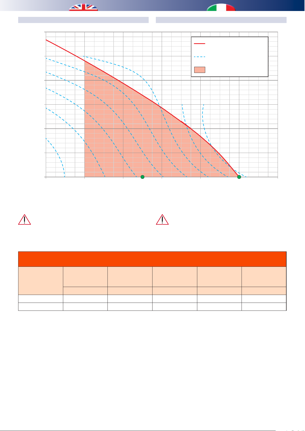
300
180
Portata aria [m3/h]
Performance [Pa]
12
25 W
250
20 W
200
15 W
10 W
150
Prevalenza utile [Pa]
100
5 W
50
VENTILATORE DI ESPULSIONEDISCHARGE FAN
MAX speed
Velocità MAX
Power consumption
Consumo elettrico
Operating range
Range di funzionamento
0
60 80 100 120 140 160
Air owrate [m
N.B. Consumi elettrici ricavati da test di laboratorio.N.B. Power consumption measured during laboratory tests.
Energy consumption only refers to the exhaust fan.
Total energy calculation shall include the power of the supply
fan.
espulsione per il calcolo energetico bisogna sommare la
potenza del ventilatore di immissione.
Chart for the output sound performance in the exhaust fan
Tabella prestazioni acustiche in uscita al ventilatore di immissione
Point
Punto
Flow rate
Portata
m3/h Pa dB(A) dB(A) dB(A)
1 110 0 41.8 30.8 21.3
2 160 0 46.4 35.4 25.9
N.B. Sound values collected through lab testing in
reverberation room.
Performance
Prevalenza
Sound power
Potenza sonora
N.B. Valori acustici rilevati da test di laboratorio eettuati
in camera riverberante.
30 W 35 W 40 W
3
/h]
I consumi elettrici sono del solo ventilatore di
Sound pressure
Pressione sonora
1 m
Sound pressure
Pressione sonora
3 m
54
Page 55

1200
0500
Portata acqua [l/h]
Head loss [DaPa]
9 - ACOUSTIC CHARACTERISTICS / CARATTERISTICHE ACUSTICHE
If the unit is installed in a false ceiling, its operation is almost
noiseless.
On the contrary, the sound of the fan can be transmitted
through the distribution ducts into the room.
Check the relevant chats in the chapter “Fan Performance”
It is recommended to install a silencer close to the
supply terminal and in the rigid ducts used to connect
it.
Il rumore prodotto dalla macchina, se installata in un
controsotto, risulta praticamente nullo.
Il rumore dei ventilatori, invece, può essere trasmesso
attraverso la linea di distribuzione e trasportato nei vari
locali. Vericare le relative tabelle nel capitolo “Prestazioni
ventilatori”
Si consiglia di prevedere un silenziatore in prossimità
della bocchetta di mandata e tubazioni rigide per il
collegamento ad essa.
10 - PRESSURE LOSS OF THE HYDRAULIC CIRCUIT / PERDITA DI CARICO CIRCUITO IDRAULICO
1000
800
600
400
Perdita di carico [DaPa]
200
0
0100 200300 40
Water ow rate [l/h]
55
DATI TECNICI
TECHNICAL DATA
Page 56
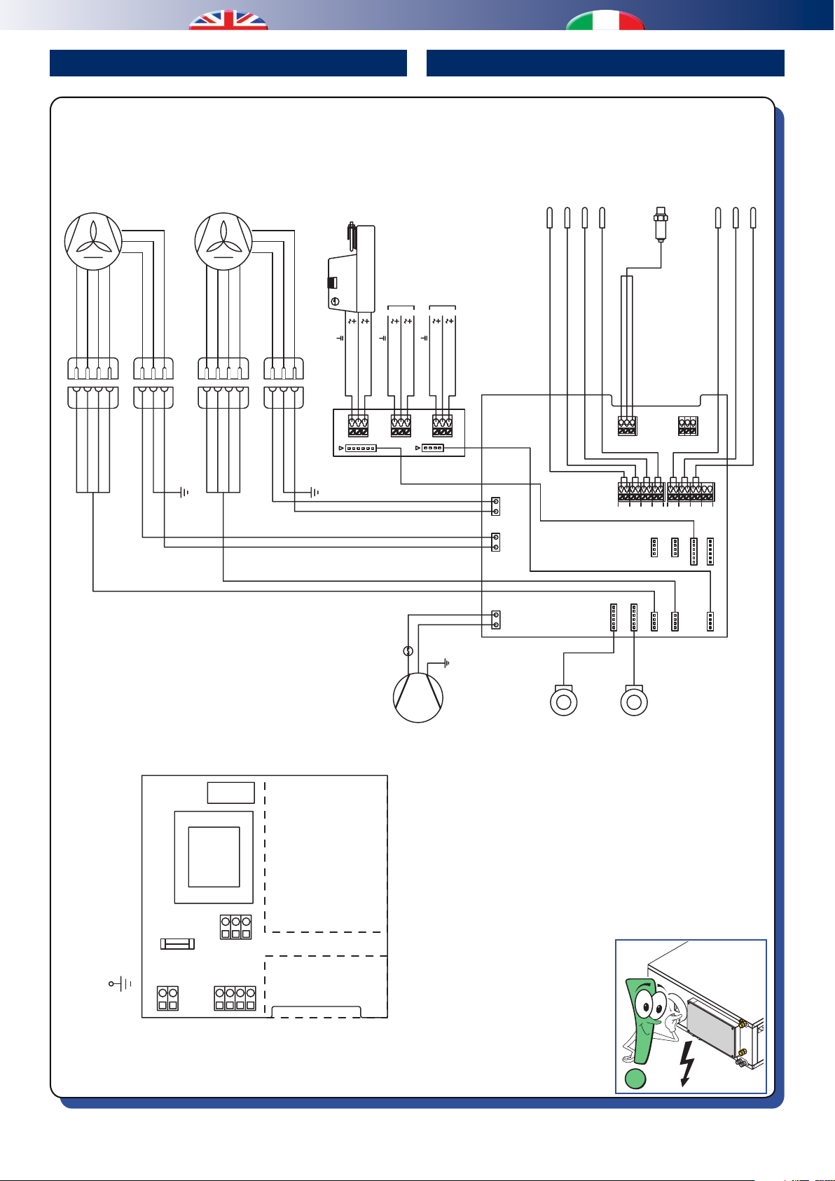
WIRING DIAGRAM SCHEMI ELETTRICI
FAN 2
VENTILATORE
GND
FAN 1
VENTILATORE
0-10v PWM
+10v OUT
MANDATA
TACH
NPEL
GND
0-10v PWM
+10v OUT
ESPULSIONE
TACH
NPEL
DAMPER
ACTUATOR
ATTUATORE
SARACINESCA
FREE
R
OPTIONAL
DAMPER
COOLING
ACTUATOR
(OPTIONAL)
1
AIR OUTLET SENSOR
TEMP. ARIA MANDATA
2
EVAPORATOR SENSOR
TEMP. EVAPORATORE
3
DISCHARGE SENSOR
TEMP. GAS DI MANDATA
UC 300-M - Rev 07
4
OVERHEATING SENSOR
TEMP. SURRISCALDAMENTO
GND - BLACK
PRESSURE
SIGN - WHITE
+5V - RED
TRANSDUCER
TRASDUTTORE
DI PRESSIONE
5
C2 SUBCOOLING SENSOR
SOTTORAFFREDDAMENTO C1
C1 SUBCOOLING SENSOR
TEMP.
6
7
SOTTORAFFREDDAMENTO C2
WATER INLET SENSOR
TEMP.
TEMP. INGRESSO ACQUA
BLUE
1
1
WHITE
GND
YELLOW
RED
2
3
2
3
YELLOW
RED
0-10v PWM
+10v OUT
WHITE
4
4
BLUE
TACH
YELLOW-GREEN
BLUE
1
2
1
2
YELLOW-GREEN
BLUE
NPEL
YELLOW
WHITE
BLUE
BROWN
3
3
BROWN
RED
1
2
3
4
1
2
3
4
YELLOW
WHITE
BLUE
RED
PE
GND
0-10v PWM
+10v OUT
TACH
YELLOW-GREEN
BLUE
1
2
1
2
YELLOW-GREEN
BLUE
NPEL
BROWN
3
3
BROWN
S1 24V
L1 24V
COM
BLUE
BROWN
L1 24V
COM
BLUE
BLACK
BROWN
P1
(WHITE-YELLOW)
MOTOR 1-2
PE
OLP
COMPRESSOR
COMPRESSORE
S1 24V
BLACK
S1 24V
L1 24V
COM
K3
K2 K1
P2
(GREEN)
MOTOR 5
LN
FAN_2
LN
FAN_1
LN
COMPR
STEPPER MOTOR
VALVE 1
MOTORE
PASSO-PASSO
VALVOLA 1
P4
P7
1
P9
EXPvalve_1
EXPvalve_2
STEPPER MOTOR
VALVE 2
MOTORE
PASSO-PASSO
VALVOLA 2
TRpress_1
H2Ovalve_1
P8
FANsign_1
P5
TRpress_2
8
NTC7NTC6NTC5NTC4NTC3NTC2NTC
NTC
P10
P11
P15
P14
H2Ovalve_2
MOT 1-2
MOT 3-4
P12
P13
P16
FANsign_2
MOT 5
REAR VIEW
VISTA POSTERIORE
POWER SUPPLY
ALIMENTAZIONE
230V - 50Hz
P3
8A
FUSE
N
PE
220VAC
H2Ovalve
SIGN
GND
24V
L
GND
A
B
+V
P1
MODbus
P2
FRONT VIEW
VISTA ANTERIORE
56
Page 57

NOTES ANNOTAZIONI
i - INFO
57
Page 58

NOTES ANNOTAZIONI
58
Page 59

Page 60

bit.ly/rdzwebsite
09/2017
9100253.08
 Loading...