

Page 1
Visit www.rdlnet.com for the complete
selection of RDL Twisted Pair Products.
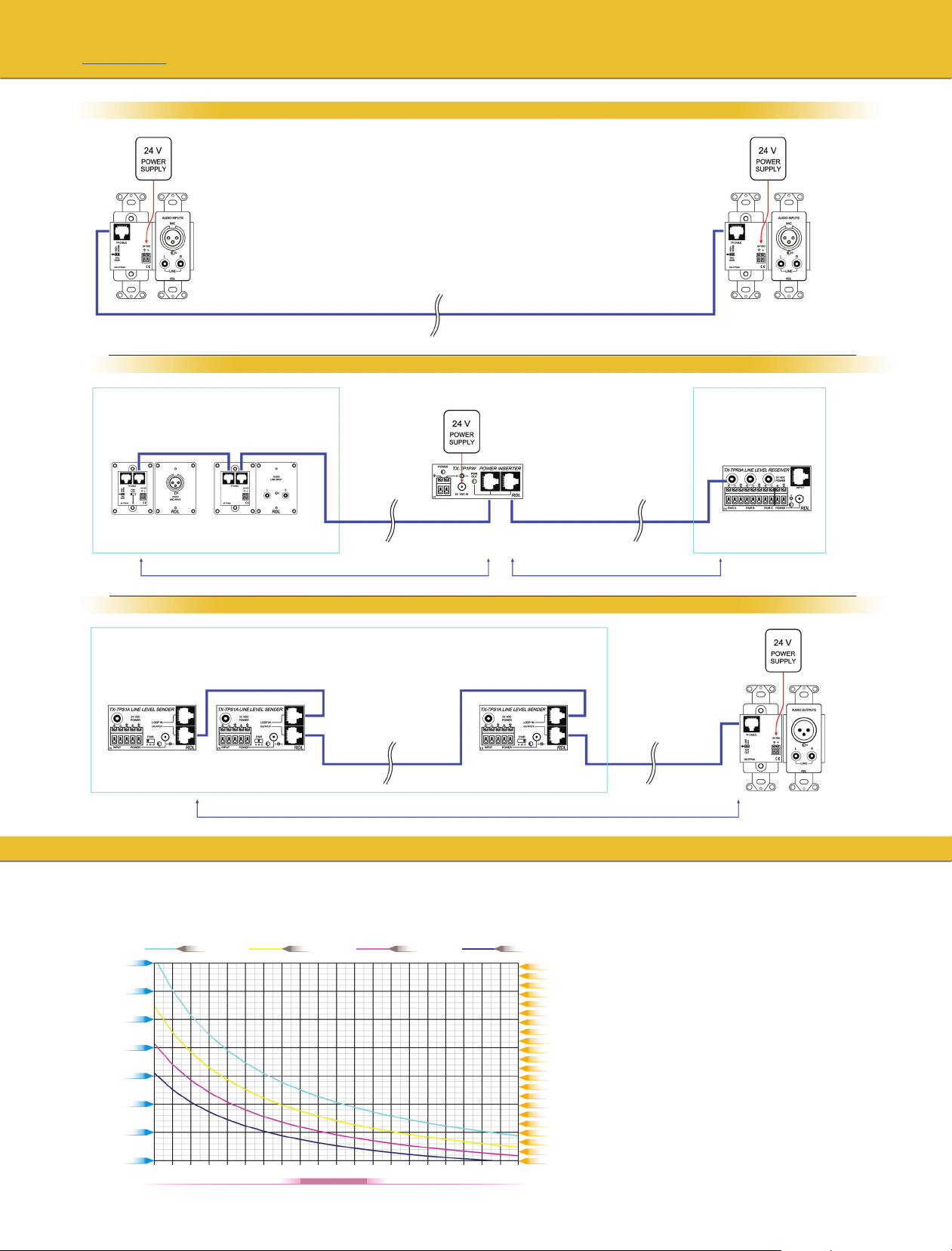
SENDING AND RECEIVING MODULES MAY BE POWERED SEPARATELY
SENDING AND RECEIVING MODULES MAY ALL BE POWERED FROM AN INSERTION POINT IN A LONG CABLE RUN
FORMAT-A POWERING
If the total distance between the sending and receiving modules is too
long to power all the modules from one end or from an insertion point in
the cable, the modules may be powered at each end of the cable run.
5
The total current of single or multiple senders
determines the maximum distance of the
SENDER(S) CABLE RUN.
SENDER(S) CABLE RUN RECEIVER(S) CABLE RUN
POWER INSERTER
Use a power supply with sufficient
current to power both cable runs and
the module that inserts the power.
Power may be inserted using an
RDL Twisted Pair Power Inserter or
a Format-A Distributor.
SENDING AND RECEIVING MODULES MAY ALL BE POWERED FROM ONE END OF A CABLE RUN
The total current of single or multiple senders
determines the maximum distance of the
SENDER(S) CABLE RUN.
SENDER(S) CABLE RUN
Use a power supply with sufficient
current to power all the modules.
The total current of single
or multiple receivers
determines the maximum
distance of RECEIVER(S)
CABLE RUN.
FORMAT-A CABLE LENGTH
MAXIMUM DISTANCE BETWEEN A POWERED MODULE AND REMOTELY POWERED MODULES BASED ON
TOTAL CURRENT CONSUMPTION OF REMOTE MODULES
2000 ft
1750 ft
1500 ft
1250 ft
Distance
1000 ft
750 ft
500 ft
250 ft
23 AWG; 20.75 Ω22 AWG; 16.5 Ω21 AWG; 13 Ω
30
40 50
70 80 90 100 110 120 130
60
Current (mA)
24 AWG; 26 Ω
600 m
575 m
550 m
525 m
500 m
475 m
450 m
425 m
400 m
375 m
350 m
325 m
300 m
275 m
250 m
225 m
200 m
175 m
150 m
125 m
100 m
75 m
Determine the maximum cable run distance from the chart.
Distances are provided for common wire gauges at various
total module currents.
CAT5 cable is normally 22 AWG; CAT6 cables range from
22 to 24 AWG.
Some twisted pair cables have a lower resistance than the
typical resistance for a specified wire gauge, and therefore
may be used over a longer distance than is shown in the
chart. The chart is based on the resistances indicated,
which is the resistance of a single conductor over 1000
feet or 300 meters. Resistance measurements on the wire
used provides the most accurate distances.
 Loading...