

Page 1

RCX™ ROOM COMBINING SYSTEM
Version 3.3
Table of Contents
1. System Overview……………………………………………………………………….. 2
2. Quick-Start / System Operation……………………………………………………….. 3
2.1 System Setup Guide………………………………………………………. 3
2.2 Equipment Planning and Wiring Guide…………………………………..4
2.3 System Operation………………………………………………………….. 5
3. System Setup……………………………………………………………………………. 6
3.1 Configuration Overview…………………………………………………….6
3.2 Instructions for Selecting Room Configuration…………………………. 7
Room Layout Diagrams…………………………………………………… 8
3.3 Instructions for Setting Power Amplifier Levels………………………….10
3.4 Instructions for Storing Preset Levels…………………………………….11
3.5 Instructions for Tandem Configuration Setup……….............................12
4. Equipment Planning and Wiring………………………………………………………..14
4.1Equipment Mounting and Prewiring Requirements…………………….. 14
4.1.1 Common Equipment Locations/System Controller…………….. 14
4.1.2 Room Audio Inputs………………………………………………… 14
4.1.3 Room Audio Control (Level and Source)………………………...14
4.1.4 Room Audio Control (Level only)………………………………… 15
4.1.5 Multiple Room Audio Controls……………………………………. 15
4.1.6 Room Combination Control Panels……………………………….15
4.1.7 Linking Two Groups of Rooms (Two Controllers)……………….16
4.1.8 Music Source……………………………………………………….. 16
4.1.9 Paging Source and Control………………………………………..16
4.1.10 Open Collector Status Outputs…………………………………… 16
4.1.11 Control Inputs………………………………………………………. 16
4.1.12 Audio Recording Outputs...........................................................16
4.2Equipment Wiring…………………………………………………………........17
4.2.1 Room Audio Input Wiring…………………………………………..17
4.2.2 Audio Output Wiring………………………………………………..19
4.2.3 Room Control Wiring……………………………………………….20
4.2.4 Background Music Input Wiring…………………………………...22
4.2.5 Paging Input Wiring………………………………………………...22
4.2.6 Connecting Auxiliary Controls and Products……………………. 23
4.2.7 RCX-CD1 Custom Control Panel………………………………… 24
5. Typical Performance……………………………………………………………………. 25
6. Mounting Dimensions……………………………………………………………………26
Radio Design Labs Technical Support Centers
U.S.A. (800) 933-1780, (928) 778-3554; Fax: (928) 778-3506
Europe [NH Amsterdam] (++31) 20-6238 983; Fax: (++31) 20-6225-287
RDL • 659 N. 6th St. • Prescott, Az., USA 86301 • (928) 443-9391 • FAX (928) 443-9392 • http://rdlnet.com
RCX
1
Page 2

1. RCX System Overview
The RCX system is an engineered room combining system configured from a variety of related products. Each system requires
an RCX-5C* Controller plus an RCX Room Control for each room. A maximum of two RCX Room Controls may be installed in
each room. The Controller may be remote controlled using one or more customized RCX-CD1 Control/Display Panels.
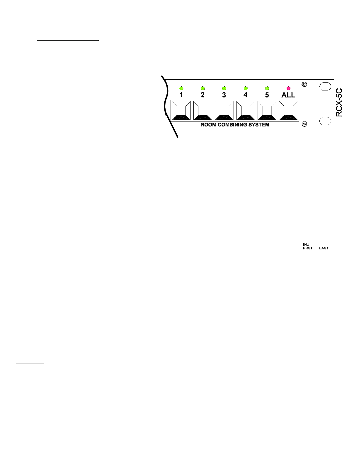
RCX-5C Controller: The system controller accommodates a maximum of 5 rooms, combined in any adjacent arrangement.
Audio inputs from each room are: LINE (only), MIC+LINE (dynamic mic), MIC+LINE (condenser mic). A front-panel level knob
with LED metering is provided for each room input. MUSIC and PAGING inputs may feed each room if desired. Two RCX-5Cs
may be linked in larger systems where two groups of rooms need to be combined. The standard RCX-5C does not mute mics
in a room while listening to music.
RCX-5CM Controller: The RCX-5CM is an RCX-5C that mutes the mics in a room while listening to background music.
RCX-CD1 Control and Display Panel: This optional remote control panel is customized by RDL with room layout graphics
matching each installation. Room combination status information and selection is provided on the panel. Multiple panels may
be connected to the RCX-5C controller. The RCX-CD1 may be ordered with key lock protection (RCX-CD1L). The
RCX-CD1(L) mounts in an equipment rack (19”, 4RU) or on a wall using the optional RDL RCX-BZL wall mount bezel.
RCX-CD1L Control and Display Panel: The RCX-CD1L is an RCX-CD1 with a keylock to prevent selecting room combinations.
The room combination display operates with the keylock is in either the LOCKED or UNLOCKED position.
RCX-1 Room Control: The standard RCX remote control features pushbutton UP/DOWN volume adjustment, and pushbutton
selection between MUSIC and LOCAL (microphones and/or line level inputs). The RCX-1 mounts in an RDL WB-2U wall box.
RCX-2 Room Control: Pushbutton selection between MUSIC and LOCAL (microphones and/or line level inputs) is adjacent to
a large rotary optical encoder knob with an LED virtual pointer. The knob controls the audio volume. The RCX-2 mounts in an
RDL WB-2U wall box.
RCX-10R Room Control: This control provides level adjustment identical to the RCX-2 except without source selection. The
RCX-10R is suited to systems in which rotary control is preferred and that do not use the background music source. It may also
be used as a second (volume only) Room Control in a system that uses background music. The RCX10R mounts in an RDL
WB-1U wall box.
RCX-3/3S Room Controls: These remote controls provide the same features as the RCX1, but require a key to activate
source selection or volume adjustment. The absence of buttons or knobs make them ideally suited to institutional use. The
RCX-3 features ULTRASTYLE design; the RCX-3S is finished in stainless steel with gray trim. Either model mounts in an RDL
WB-2U wall box.
RCX-3R/3RS Room Controls: These remote controls provide up/down key operated volume control for systems that do not
use a background music source. The RCX-3R features ULTRASTYLE design; the RCX-3RS is finished in stainless steel with
gray trim. Either model mounts in an RDL WB-2U wall box.
Note: RCX-5C: When the MUSIC source is selected on an RCX-1, RCX-2 or RCX-3, the system background music is
switched on and the local inputs remain active, permitting users to make announcements over the music without selecting LOCAL
on the wall control. When LOCAL is selected, the background music is disabled in the room.
RCX-5CM: When the MUSIC source is selected on an RCX-1, RCX-2 or RCX-3, the system background music is switched on
and the local inputs are muted. When LOCAL is selected, the background music is disabled in the room.
RCX-J1 Microphone Input Panel: This input panel provides a microphone input (XLR).
RCX-J2 Line Input Panel: This input panel installs in a room to provide a stereo unbalanced line level input (phono jacks). The
line inputs are passively mixed to mono and transformer balanced.
RCX-J3 Microphone + Line Input Panel: This input panel installs in a room to provide both a microphone input (XLR) and a
stereo unbalanced line level input (phono jacks). The line inputs are passively mixed to mono and transformer balanced.
RCX-A2 Audio Output Panel: This output panel provides two -10 dBV (left and right) outputs from the room audio signal. The
RCX-A2 is mounted in a room to allow users to record the audio in that room. The output signals are transformer isolated from
the room amplifier feed.
Note: The RCX-J1, J3 and A2 mount in RDL WB-1U wall boxes.
*Unless otherwise stated, references to the RCX-5C apply to all current RCX-5C models.
RCX
2
Page 3
2. QUICK-START / SYSTEM OPERATION
2.1 System Setup Guide
The QUICK-START System Setup Guide is intended to familiarize new users with system setup. It is also
intended as a functional installation guide and checklist for installers who have previously connected and set up
an RCX system. The complete RCX instructions in Sections 3 and 4 should be read, understood and followed
for first time installations.
SELECT ROOM CONFIGURATION
1] Hold Button 1 in while powering up the
RCX-5C. LED 1 flashes during setup.
2] Find room layout (Section 3.2). Set rear-
panel MODE switch and buttons as shown.
3] Only if ‘continuous’ remote inputs are used,
set Button ALL LED to on.
(Default inputs are ‘momentary’ as required if RCX-CD1 is connected to RCX-5C)
4] Push Button 1 to save settings, exit Room Configuration Setup and assume normal operation.
SET POWER AMPLIFIER LEVELS
1] Turn power amplifier gain off for room being adjusted.
2] On RCX Room Control, select LOCAL and ramp level to maximum.
3] Connect a typical source (usually mic) providing usual audio level.
4] Use front-panel dual-LED meter to set corresponding level knob.
5] Adjust power amplifier gain for the maximum level ever desired.
6] Ramp level off and repeat for all other rooms.
STORING PRESET LEVELS
Note: Default preset levels are 18 dB below max.; storing
new levels is optional.
1] Set all room levels off by repowering RCX-5C
with the rear-panel PRESET button held in.
2] Turn level up to desired level (on only one RCX room
control at a time).
3] Push PRESET button; LED will illuminate steady for 3 seconds.
(If more than one room is turned up (not off), LED flashes indicating error.)
4] Ramp level to off position (red LED on) and repeat steps 1-3 for other rooms.
5] If MUSIC is used, repeat steps 1-4, but set RCX Room Controls for MUSIC source.
SET UNCOMBINED ROOMS TO USE EITHER THE PRESET OR LAST LEVEL USED
1] Set the IND RM LEVEL rear panel switch to PRST if the preset level is desired upon selecting
the LOCAL source in any uncombined room; or
2] Set the IND RM LEVEL switch to LAST to return to the last local level setting upon selecting LOCAL.
TANDEM LEVEL CONTROL AND/OR SOURCE SELECTION
Note: Room level control and source selection initially default to TANDEM; storing other modes is optional. (TANDEM control
causes the RCX Room Control(s) in a combined room to control the level and/or source selection in all associated combined
rooms. When MUSIC LOCKOUT source selection mode is active, the controller will force all Room Controls to the LOCAL source
when the associated room is combined. If any room in the system is equipped only with Room Controls that do not provide
source selection [RCX-10R, RCX-3R, RCX-3RS], then the MUSIC LOCKOUT mode must be programmed.)
1] Repower RCX-5C with Button ALL held in. LED ALL flashes during setup.
2] Set Button 1 LED on for TANDEM volume control (factory default); off for INDEPENDENT
3] Set Button 2 LED on for TANDEM source select (factory default); off for MUSIC LOCKOUT
4]
Push Button ALL to save settings, exit Tandem Configuration Setup and resume operation.
RCX
3
Page 4

2.2 Equipment Planning and Wiring Guide
Minimum rectangular
MOUNTING REQUIREMENTS
Width Height
RCX-A2 Use RDL WB-1U (US/International) or US single electrical box* 1.80” (4.60 cm) x 2.73” (6.93 cm)
RCX-J1 Use RDL WB-1U (US/International) or US single electrical box* 1.80” (4.60 cm) x 2.73” (6.93 cm)
RCX-J2 Use RDL WB-1U (US/International) or US single electrical box* 1.80” (4.60 cm) x 2.73” (6.93 cm)
RCX-J3 Use RDL WB-1U (US/International) or US single electrical box* 1.80” (4.60 cm) x 2.73” (6.93 cm)
RCX-1 Use RDL WB-2U (US/International) or US double electrical box** 3.55” (9.02 cm) x 2.73” (6.93 cm)
RCX-2 Use RDL WB-2U (US/International) or US double electrical box** 3.55” (9.02 cm) x 2.73” (6.93 cm)
RCX-3 Use RDL WB-2U (US/International) or US double electrical box** 3.55” (9.02 cm) x 2.73” (6.93 cm)
RCX-10R Use RDL WB-1U (US/International) or US single electrical box* 1.95” (4.95 cm) x 2.73” (6.93 cm)
RCX-5C Rackmounted, 1RU, leave ventilation above and below
RCX-CD1(L)Rackmounted, 4RU; Wallmounted using RDL RCX-BZL
* Note that US single gang masonry boxes are a substandard width not suitable for these products.
**If US “square” electrical box is installed with a mud ring, use the RDL MR-2 (available separately)
in place of any mud ring that does not provide the minimum required rectangular clearance.
WIRING REQUIREMENTS
RCX-5C Audio inputs and outputs use standard single shielded pair.
Interconnect with other RCX components using wires listed below:
RCX-A2 Single shielded pair audio wire (normally 24 gauge / 0.22 mm2 or heavier)
RCX-J1 Single shielded pair audio wire (normally 24 gauge / 0.22 mm2 or heavier)
RCX-J2 Single shielded pair audio wire (normally 24 gauge / 0.22 mm2 or heavier)
RCX-J3 Two shielded pairs audio wire (normally 24 gauge / 0.22 mm2 or heavier)
RCX-1 5 conductors, or two shielded pairs (normally 24 gauge** / 0.22 mm2 or heavier)
RCX-2 5 conductors, or two shielded pairs (normally 24 gauge** / 0.22 mm2 or heavier)
RCX-3 5 conductors, or two shielded pairs (normally 24 gauge** / 0.22 mm2 or heavier)
RCX-10R 4 conductors (normally 24 gauge** / 0.22 mm2 or heavier)
RCX-CD1 15 conductors (normally 24 gauge** / 0.22 mm2 or heavier)
clearance inside box
** For wire lengths 100 m (330 ft) to 300 m (1000 ft), 20 gauge / 0.5 mm2 (min.) wire is required.
For wire lengths 300 m (1000 ft) to 600 m (2000 ft), 18 gauge / 1.0 mm2 (min.) wire is required.
Notes: 1] A maximum of two Room Controls (RCX-1, RCX-2, RCX-3, RCX-10R) may be installed in
each room by continuing the wiring run from the first remote to the second remote, or by
making a ‘home run’ from each Room Control back to the RCX-5C.
2] Multiple RCX-CD1 panels may be connected to a single RCX-5C by continuing the wiring run
from the first RCX-CD1 to subsequent RCX-CD1s, or by making a ‘home run’ from each
RCX-CD1 back to the RCX-5C.
WIRING DETAILS
Audio wiring follows industry standards for balanced and unbalanced wiring. Unbalanced inputs require that the
“-” input terminal be connected to ground. Unbalanced outputs are connected between “+” and ground; no
connection to “-”.
RCX Room Controls wire directly to the corresponding numbered terminal on the rear of the controller: 1 to 1,
2 to 2, 3 to 3, 4 to 4, 5 to 5, 6 to 6.
Use a standard stereo RCA patchcord to link two RCX-5C controllers together.
RCX
4
Page 5

2.3 System Operation
AUDIO INPUT LEVEL ADJUSTMENT
There are 5 audio input level knobs on the RCX-5C front panel. Above each knob is a corresponding RDL dualLED VU meter. When audio from a room is present, the green LED should pulse brightly with the red LED
flashing only occasionally. When mics (or other sources) are set up in a room for a sound check, adjust the
corresponding RCX-5C front panel input knob for the correct level on the dual-LED VU meter.
COMBINING AND UNCOMBINING ROOMS
There are 6 pushbuttons on the front panel of the RCX-5C. Five buttons correspond to walls that may divide an
area into separate rooms. When a wall is open, adjacent rooms are combined to form a single room. Push the
button that corresponds to the open wall to combine the audio in the adjacent rooms. The green LED above the
button glows when the adjacent rooms are combined. Pressing the button again will uncombine the rooms.
WHAT HAPPENS WHEN ROOMS ARE COMBINED
When rooms are combined, the audio jack(s) in each combined room are mixed together, and the combined
audio feeds the speaker amplifiers in each of the combined rooms. When a room combination button is pushed,
the audio level in each of the affected rooms is automatically set to a ‘preset’ level determined by the installer if
the RCX-5C is in the TANDEM level mode. If the RCX-5C is in the INDEPENDENT level mode, entering a combination
sets each room to LOCAL and selects either the preset or last local level used, depending on the position of the rear
panel IND RM LEVEL switch. If the factory defaults were not changed during initial setup, the controls in each
combined room operate in tandem. Source selection or volume adjustment is possible from any control in the
combined room. (The installer may set up the system to leave the volume adjustment independent in each room, or
to lock out the MUSIC source from being selected when rooms are combined.)
COMBINING ALL ROOMS
Pushing Button ALL causes all active rooms in the system to be combined and all Room Controls to be set to the
LOCAL source. It also causes all audio levels to be set to the levels described in preceding section. All (microphone
and/or line level) audio inputs in the rooms will be heard in all rooms. If the RCX-5C is linked to another RCX-5C, the
audio in all rooms on both controllers is sent to the speaker amplifiers associated with both controllers when ALL
combine is selected on both controllers.
VISUAL CONTROL PANEL
If the system installation includes an RCX-CD1, adjacent rooms may be combined or uncombined according to
a button placed on a graphic view of the room layout. Each combine button on the
RCX-CD1 is located in a ‘wall’, and each such button corresponds to a front-panel button on the RCX-5C
controller. Pushing a button shown in a ‘wall’ combines the adjacent rooms and turns on its associated green
LED. Pushing the button again deselects the combination. The RCX-5C front-panel buttons remain active with
an RCX-CD1 connected. The RCX-CD1 also provides an ALL combine button with LED, and may be equipped
with a key lock (RCX-CD1L) to enable/disable the buttons.
ERROR INDICATION
Rooms must be combined with adjacent rooms to form a single larger room. If two separate pairs of rooms have
been combined, pushing a button between the two groups results in an error. An error is indicated by rapid
flashing of the red LED above the ALL combine button.
PAGING
Activate the installer-provided switch to page into all rooms. Paging interrupts all other audio and overrides the
individual levels set in each room. Two seconds after the paging switch is released, all audio returns to the
previous sources and levels.
RCX
5
Page 6

3. System Setup
3.1 CONFIGURATION OVERVIEW
As shipped from the factory, the controller is configured as a 2 Room System with momentary REMOTE control
inputs, tandem ‘combined room’ volume controls, tandem ‘combined room’ source selection and ‘preset’ stored
levels set midscale. If this is your system, you may skip the configuration section.
3.1.1 Required:
If your system has more than two rooms, it must be configured prior to operation. This may be done with the
controller installed in the rack, or more easily on the bench prior to installation. The configuration is permanently
stored. Once saved, this setup does not need to be repeated. If there is a future change in the room layout (such
as a renovation to add a new room), the controller may be reconfigured (5 rooms max.).
Configuration is simple and straightforward. Only four parameters must be selected. If the factory default is
set to the desired parameter, then no action is required by the installer.
1] Select Configuration of Rooms
Number and Layout of Rooms (from Room Layouts diagrams, Section 3.2)
2] Set REMOTE inputs (if used) as MOMENTARY or CONTINUOUS
Controller rear-panel control inputs must be set to MOMENTARY (factory default) if a remote
pushbutton panel is to be used to select room configurations. These inputs are set to CONTINUOUS
if the controller is intended to switch automatically based on continuous closures provided by external
switches (example: magnetic switches triggered by the position of moving partitions). Note: If the
CONTINUOUS mode is selected, then applying an external switch closure to a particular input will
over-ride and disable the associated front-panel button until the switch opens. In the absence of an
external closure, the front-panel buttons will function normally.
3] Select INDEPENDENT or TANDEM room level control
TANDEM control (factory default) allows any RCX Room Control to adjust the level simultaneously
in all the rooms comprising the larger combined room. (The TANDEM mode may be preferred in
systems that allow overhead speakers to be disabled in the area where microphones are used, or
that have feedback controllers installed.) INDEPENDENT control allows the level in each room to
be independently adjusted when the room is part of a larger combined room. (This setting may be
preferred in installations that do not have feedback control or the provision to turn off overhead
loudspeakers in the area where microphones are used.)
4] Select TANDEM or MUSIC LOCKOUT source selection
TANDEM control (factory default) allows any RCX Room Control that provides source selection to
select the MUSIC or LOCAL source simultaneously in all the rooms comprising the larger combined
room. MUSIC LOCKOUT mode disables the MUSIC source selection in any room that is combined.
This setting may be preferred by a facility wishing to preclude the possibility of background music
being turned on after a combined room has been set up.
RCX
6
Page 7

3.1.2 Optional:
The controller allows the installer to store PRESET audio volume levels for each room. This setup may be done
only after completion of physical installation and wiring of the system. Two separate preset levels are stored per
room; one for the MUSIC input, one for the LOCAL input. Storing the correct level for a ‘typical’ room use will
facilitate subsequent system operation. For example, a mic can be set up in a room, and a room combination
selected on the controller. Selecting the room combination sets the associated room audio sources to LOCAL
and sets the volume to the stored value. Therefore, no further action is required to prepare for normal room use;
level changes can always be made in the room if desired.
As shipped from the factory, the RCX Room Control audio level will be halfway up when either input is selected
in any room. The factory setting allows levels to be adjusted +/- 18 dB in each room. This range is suitable for
many facilities, simplifying installation by making level storage unnecessary.
3.1.3
If the TANDEM control mode is active and a room is made part of a combination, its source is set to LOCAL and the
level is set to PRESET. If the INDEPENDENT control mode is active, a newly combined room’s level will go to the last
stored local level if the IND RM LEVEL switch is set to the LAST position. The audio level in the room may then be
adjusted to a different volume. If MUSIC is selected in the combined room, the last LOCAL level setting is stored in
memory. Upon reselecting LOCAL, the volume returns to the last level. In a room that is not part of a combination, the
LOCAL level can be set to return either to PRESET or to the LAST LOCAL level setting when the room source is
switched from MUSIC to LOCAL. If the RCX-5C rear panel IND RM LEVEL switch is set to the PRST PRESET
position, the audio level will always return to the stored local preset level when a user switches the room source from
MUSIC to LOCAL. If the RCX-5C rear panel IND RM LEVEL switch is set to the LAST position, the audio level will
always return to the previous local level when a user switches the room source from MUSIC to LOCAL.
3.2 INSTRUCTIONS FOR SELECTING ROOM CONFIGURATION
1] Hold Button 1 in while powering up the controller; release it when the LED above it turns on. The LED
above Button 1 will flash to indicate the ROOM CONFIGURATION setup mode is active. It will continue to flash
until the configuration settings are saved.
(Note: DO NOT push Button 1 again until you are done selecting the correct configuration settings. Pushing Button 1 stores the
configuration and exits the configuration mode. If you accidentally push Button 1 prematurely, you may re-enter the configuration
mode by repeating Step 1.)
2] Find your room layout from the diagrams on the following pages. Set the rear-panel MODE SWITCH to the
position shown. Then set the button LEDs on or off as shown on the button diagram associated with your layout.
The LEDs toggle on/off each time buttons are pushed.
(Note: If you push a button that would also require another LED to be set ‘on’ (or ‘off’), the controller will automatically set the
other LED(s) ‘on’ (or ‘off’) to simplify your setup. If no MODE SWITCH position is indicated, then the switch may be in any
position.)
3] Set the REMOTE CONTROL input terminals for CONTINUOUS closure operation if desired. (Factory
default is MOMENTARY.) CONTINUOUS operation is selected by toggling Button ALL LED on. (CONTINUOUS
mode is used if the RCX-5C is controlled by external switches activated by wall positions.)
4] Push Button 1 to save your settings. LED 1 will stop flashing and the system enters the normal operating mode.
RCX
7
Page 8
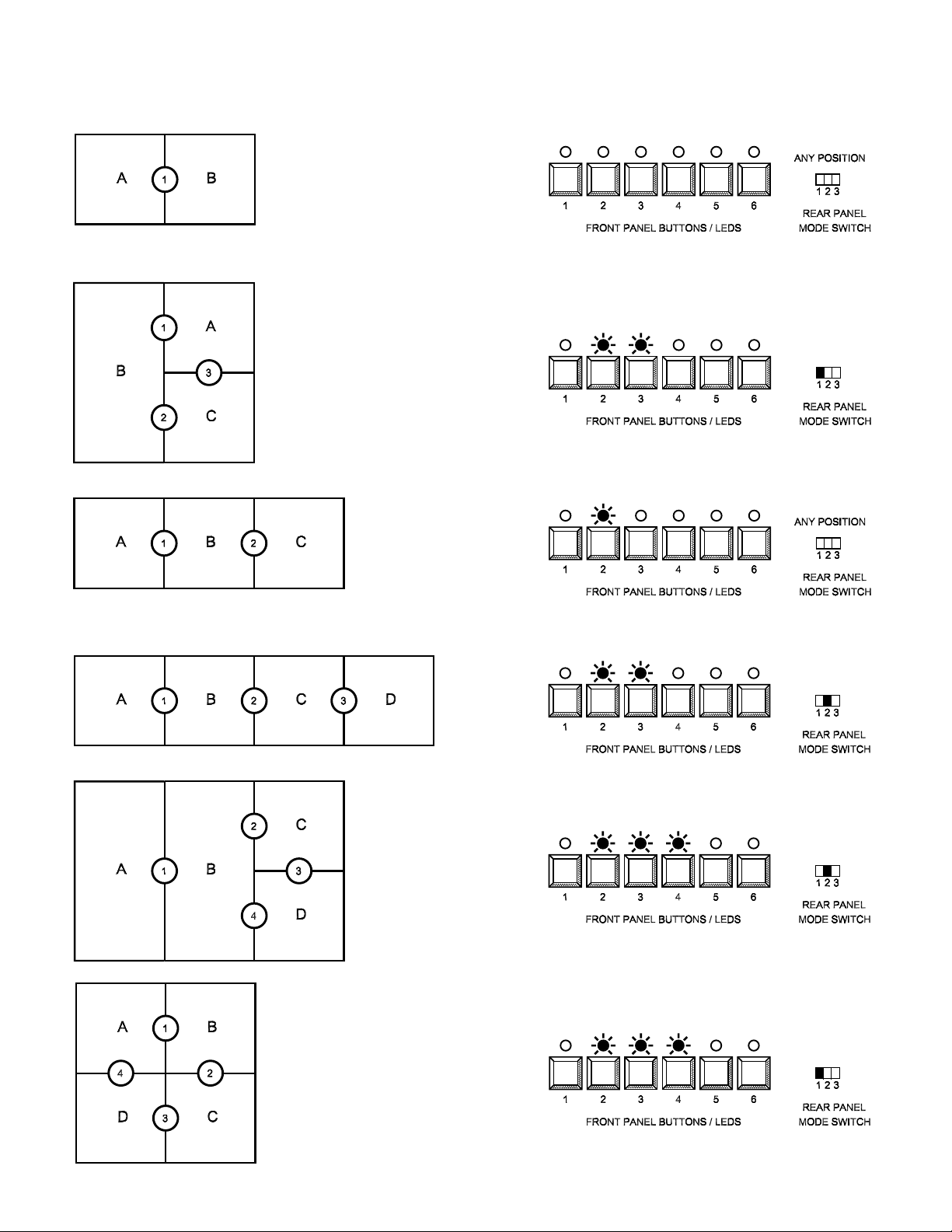
2 ROOM SYSTEM
3 ROOM SYSTEMS
Room Layout Diagrams
4 ROOM SYSTEMS
RCX
8
Page 9

4 ROOM SYSTEMS (CONTINUED)
5 ROOM SYSTEMS
RCX
9
Page 10

3.3 INSTRUCTIONS FOR SETTING POWER AMPLIFIER LEVELS
3.3.1
The controller audio output for each room is a nominal +4 dBu line level to feed the power amplifier used for that
room. Before storing preset levels in the controller, it is first necessary to set the
power amplifier gain. Once set, the power amplifier gain controls should be
secured against tampering.
1] Turn the power amplifier gain to the off position.
2] Connect the typical mic or mixer that will be used in Room A. Speak into
the mic to verify the correct audio level at the controller, as indicated by the
dual-LED VU meter on the front panel. If required, adjust the front panel knob
associated with Room A for correct operating level (green LED as bright as
possible, with the red LED flashing only occasionally).
3] In Room A, select LOCAL source on the RCX Room Control and ramp the audio level fully up, indicated by
the uppermost red LED on the level LED string.
Required:
(Note: Experienced installers may save considerable time by consolidating related steps for setting and storing levels. The
following individual steps are presented to ensure trouble-free installation and a thorough understanding of the controller
operation.)
4] Adjust the gain of the room’s power amplifier for the maximum level desired. This may be the highest level
possible without feedback.
(If acoustic conditions produce feedback at an insufficient audio level, a line-level audio equalizer should be
installed between the controller audio output and the power amplifier input. An example is: RDL FP-PEQ3 3band Parametric Equalizer.)
5] Ramp the RCX Room Control level to the off position (lowest red LED illuminated), and repeat
steps 2], 3], 4] and 5] for all other rooms.
3.3.2 Optional:
After setting the input gains (3.3.1, step 2] above), the installer may wish to protect the RCX-5C against
unauthorized adjustment. The level controls on the front of the RCX-5C are intended to be adjusted occasionally
if different mics or mixers are used in a particular setup. The RCX-5C is supplied with a provision to protect
against unwanted level adjustment. Five plastic caps are provided, which may be used to replace the frontpanel knobs. The caps have a small hole in the center that allows access for a standard alignment screwdriver.
To install the caps, first remove the knobs by snapping out the knob cap, loosening the screw and removing the
knob. Snap the plastic cap in place.
RCX
10
Page 11

3.4 INSTRUCTIONS FOR STORING PRESET LEVELS
‘Preset’ levels may be ‘permanently’ stored at any time during normal operation. Each level remains stored until
it is changed and stored again. During routine operation, the volume in a room will return to the preset level
when the MUSIC source is selected or when the room is first combined with another room. In an uncombined
room, the volume will return to the preset level when LOCAL is selected, provided the rear panel selector is set
for that function (see 3.1.3). Two levels may be stored for each room. One level is stored for the MUSIC source,
typically a low level for background music. A second preset level is stored for the LOCAL source, typically the
normal public address operating level for combined rooms chosen by the installer.
(Note: Factory default preset levels are 18 dB below maximum; storing new levels is optional. The default setting is shown on the
RCX Room Control level indicator as 5 of 10 LEDs illuminated,
allowing a nominal user adjustment of +/- 18 dB.)
1] Set the level in each room to the off condition, as
indicated by the bottom red LED on the RCX Room Control.
A special utility in the RCX-5C allows setting all room levels
off at the controller. On the back of the controller, remove
power, then reconnect power while holding the PRESET
button in. After connecting power, release the PRESET button
and the RCX-5C resumes normal operation with all RCX
Room Controls in the off position. The stored ‘preset’ levels
are not changed by this operation.
(Note: The level storage mode is only enabled if one room level is turned up. If two or more RCX Room Controls are turned up
[not ‘off’] then level storage is not allowed. Also, if no RCX Room Controls are turned up, then storage is not allowed.)
(Note: If power fails and is restored during normal operation, audio returns to the local mode preset level.)
2] Connect the typical mic or mixer that will be used in Room A. Speak into the mic
to verify the correct audio level at the controller, as indicated by the dualLED VU meter
on the RCX-5C front panel. If required, adjust the frontpanel knob associated with
Room A for correct operating level (green LED as bright as possible, with red LED
flashing only occasionally).
3] In Room A, select LOCAL source on the RCX Room Control and adjust the audio
level for desired volume.
4] Press the PRESET button on the rear of the controller. The red LED on the rear panel will illuminate
(steady) for 3 seconds, indicating the value is stored.
(Note: If the red LED flashes, the value is not stored. This error condition occurs if more than one RCX Room Control is set to a
level other than ‘off’ or if all Room Controls are ‘off’. Ramp the levels down to ‘off’ in all rooms [see step 1 in this section] except
the room you wish to store, then repeat this step.)
5] Ramp the level down to off in Room A. Repeat steps 2], 3], 4] and 5] for the other installed rooms.
(Note: It is not necessary to store values for every room. If the factory default ‘half volume’ is desired in some rooms, then store
new values only for the rooms requiring different preset levels.)
If background music is not used in your installation, skip to step 10].
RCX
11
Page 12

6] Verify the correct audio level of the music source on the
controller, as indicated by the dual-LED VU meter on the front panel.
If required, adjust the rear-panel music level trimmer for correct
operating level (green LED as bright as possible, with red LED
flashing only occasionally).
7] In Room A, select MUSIC source on the RCX Room Control and adjust audio level for desired volume
using the UP and DOWN buttons (RCX-1), using the rotary encoder (RCX-2, RCX-10R) or using the key switch
(RCX-3).
(Note: If the room is combined with another room, the MUSIC source button on the RCX Room Control may be locked out by the
controller.)
8] Press the PRESET button on the rear of the controller. The red LED on the rear panel will illuminate
(steady) for 3 seconds, indicating the value is stored.
(Note: If the red LED flashes, the value is not stored. This error condition occurs if more than one RCX Room Control is set to a
level other than ‘off’, or if all Room Controls are ‘off’. Ramp the levels down to ‘off’ in all rooms except the room you wish to store,
then repeat this step.)
9] Ramp the level down to off in Room A. Repeat steps 6], 7], 8] and 9] for the other installed rooms.
If paging is not used in your installation, skip step 10].
10] Connect the PAGING control terminal to ground to activate the paging mode. Apply line level paging audio
to the PAGING audio input. Adjust the controller rear-panel paging trimmer control for the desired audio level.
The level will be the same for all rooms regardless of which source (MUSIC or LOCAL) is selected in that room.
Paging overrides both the source and level settings on each RCX Room Control. Disable PAGING after adjustment
to return to normal operation.
The level settings are complete.
3.5
INSTRUCTIONS FOR TANDEM CONFIGURATION SETUP
(SETTING TANDEM OR INDEPENDENT LEVEL CONTROL
AND FOR SETTING TANDEM OR MUSIC LOCKOUT SOURCE SELECTION)
TANDEM OR INDEPENDENT LEVEL CONTROL: As supplied from the factory, the volume control in each
combined room adjusts the audio level in the entire combined area. This is called the TANDEM level control
mode. Installations without feedback controllers or a provision to turn off speakers located over microphone
locations may benefit from independent level control. When the INDEPENDENT mode is set, the volume is
adjusted individually in each combined room in a combined area. (This permits the staff to reduce the volume in
the room where mics are set up while setting the volume louder in the rest of the combined room.) The RCX-5C
may be toggled between the INDEPENDENT mode or the default TANDEM mode. (In the TANDEM mode, all
room volume controls in a combined room will adjust the level in the entire combined room. When first combined,
the room level is set to the LOCAL preset level. Subsequent switching from the MUSIC to the LOCAL source in
the combined room causes the LOCAL level to return to the last LOCAL level setting.)
TANDEM OR MUSIC LOCKOUT SOURCE SELECTION: As supplied from the factory, the source selector
(if the Room Control is equipped with source selection) in each combined room will select the MUSIC or LOCAL
source for the entire combined area. This is called the TANDEM source selection mode.
RCX
12
Page 13

Some facilities may prefer that the MUSIC source be locked out (unavailable) in a combined area. When the
MUSIC LOCKOUT mode is active, the MUSIC button on each Room Control in a combined area will not change
the source when pushed. (The MUSIC LED will flash to acknowledge the button, but the source will remain in
LOCAL.) Most systems are designed with similar Room Controls in each room; if background music is used at
all, it is typically used in all rooms. It is possible to install an RCX system with source selection (MUSIC or
LOCAL) in some, but not all, rooms. If any room in a system using background music is equipped only with a
room control that does not provide source selection, then the MUSIC LOCKOUT mode must be chosen.
Note: If none of the Room Controls in the system have source selection, then the RCX-5C may be set to either MUSIC
LOCKOUT or INDEPENDENT source selection mode.
The following setup allows the installer to set the modes that will be applied every time a room combination is
selected. These settings are used permanently unless they are changed in the future using this procedure:
1] Remove power from the RCX-5C, if it is powered.
2] Hold down Button ALL while connecting power to the RCX-5C. The LED above Button ALL will flash,
indicating the TANDEM CONFIGURATION SETUP is active. It will continue to flash until the configuration settings
are saved.
3] Observe the Button 1 LED. If it is on, the RCX-5C is set for TANDEM level control. Press Button 1 to toggle
the level control to INDEPENDENT, if desired. Pushing Button 1 alternates the mode between TANDEM and
INDEPENDENT.
4] Observe the Button 2 LED. If it is on, the RCX-5C is set for TANDEM source selection. Press Button 2 to
toggle the source selection to the MUSIC LOCKOUT mode. Pushing Button 2 alternates the mode between
TANDEM and MUSIC LOCKOUT.
5] Push Button ALL to save your settings. LED ALL will stop flashing and the system enters the normal
operating mode.
RCX
13
Page 14

4. Equipment Planning and Wiring
All RCX components are designed to be connected using readily available standard wire and cable types. For
ease of testing and troubleshooting, audio wiring carries standard analog audio signals. Control wiring carries
power and dc voltages. Command pushbuttons shift dc levels permitting easy wiring verification using a multimeter.
All terminals providing dc power from the RCX-5C are protected against accidental shorts. Automatically resetting
fuses remove power from shorted wiring and restore power when the wiring fault is corrected. Long control
cable runs require heavier gauge wires as detailed in Section 2.2.
4.1 EQUIPMENT MOUNTING AND PREWIRING REQUIREMENTS
4.1.1COMMON EQUIPMENT LOCATION / SYSTEM CONTROLLER(S)
Each system is controlled by an RCX-5C Controller. The RCX-5C mounts in an equipment rack with its power
supply (RDL PS-24U2) and the room power amplifiers. A typical system (providing a single microphone input
and a stereo unbalanced line input in each room) does not require any additional mixing equipment. If multiple
inputs are desired in each room, audio mixers may be either rack mounted with the RCX-5C or may be wall
mounted in each room. RDL offers a range of mixers for this purpose. The RCX-5C occupies 1RU and requires
ventilation within the rack. It is recommended that the equipment mounted in the rack unit above and below the
controller be no deeper than 2 inches (5 cm), or use an RDL RM-FP1 filler panel. RDL Rack-Up series products
and RCX-CD1(L) custom control panels may be mounted directly above and below an RCX-5C controller. The
PS-24U2 power supply may be optionally rack mounted using an RDL RURA3 rack adapter and PSB-1 power
supply bracket.
SUMMARY
MOUNTING: RCX-5C requires 1 rack unit, allow 1RU above and below for ventilation
ELECTRICAL: 24 Vdc, 2 A from RDL PS-24U2
4.1.2 ROOM AUDIO INPUT(S)
Each room must be equipped with at least one input. The RCX-5C has two inputs per room, one MIC and one
LINE. Each input is balanced and may be wired unbalanced. Typical installations use either an RCX-J1 (single
microphone jack assembly), an RCX-J2 (summed stereo phono jack line input) or an RCX-J3 (single microphone
jack plus a summed stereo phono jack line input). If the RCX-J1 or RCX-J2 is used, a single shielded pair is
required from the room to the rack. If the RCX-J3 is used, two shielded pairs (in either a separate or common
jacket) are required from the room to the rack. If additional inputs are to be used, the installer may use RCX-J1,
RCX-J2 or RCX-J3 assemblies as inputs to a separate mixer. The mixer is used to feed the line level input of a
given room input on the RCX-5C.
SUMMARY
MOUNTING: RCX-J1, RCX-J2, RCX-J3 mounts in RDL WB-1U wall box or single US electrical box
WIRING: RCX-J1, RCX-J2: Single shielded pair ; RCX-J3: Two shielded pairs
4.1.3 ROOM AUDIO CONTROL (LEVEL AND SOURCE)
Each room is also equipped with an RCX Room Control for adjusting volume and selecting the audio source
(facility music source or local room inputs). If no system music source is desired in any or all rooms, install an
RCX Room Control without source selection. A typical system is installed with RCX-1 Room Controls (pushbutton
volume [up/down], plus pushbutton source selection [MUSIC/LOCAL]). For customers desiring rotary level
control, the system is installed with RCX-2 Room Controls (rotary encoder volume [up/down], plus pushbutton
source selection [MUSIC/LOCAL]). For customers desiring keyed operation, the system is installed with
RCX-3 Room Controls (mechanical key switch for volume [up/down], mechanical key switch to select source).
RCX
14
Page 15

Wiring from the RCX Room Control to the rack is identical for each of these controllers. Five conductors are
required, one of which is grounded and may be a shield. These may be 5 individual conductors, 2 shielded pairs
or 4 conductors plus a separate ground. Cat 5 wire or equivalent may be used. Control is dc, allowing verification
using a simple multimeter and requiring no special data wiring precautions.
SUMMARY
MOUNTING: RCX-1, RCX-2, RCX-3 mount in RDL WB-2U wall box or double US electrical box
Note: If US electrical box uses a mud ring, replace mud ring with RDL MR-2;
(Some mud rings have large radii that interfere with RCX product mounting).
WIRING: 5 conductors 24 gauge or heavier (see Section 2.2), or two shielded pairs audio wire
4.1.4 ROOM AUDIO CONTROL (LEVEL ONLY)
For systems not using a music source, the RCX-10R, RCX-3R or RCX-3RS Room Controls may be used. The
RCX-10R is a rotary optical encoder with an LED virtual position pointer. The RCX-3R and RCX-3RS are key
operated panels with an LED virtual position pointer. Four conductors are required from the RCX-5C to any of
these Room Controls. One of the four conductors is grounded and may be a shield. These may be 4 individual
conductors or 3 conductors plus a ground or shield. Cat 5 or equivalent may be used. Control is dc, allowing
verification using a simple multimeter and requiring no special data wiring precautions.
SUMMARY
MOUNTING: RCX-10R mounts in RDL WB-1U wall box or single US electrical box
WIRING: 4 conductors 24 gauge or heavier (see Section 2.2)
4.1.5 MULTIPLE ROOM AUDIO CONTROLS
A typical system has a single RCX Room Control in each room. It is possible to provide one or two RCX Room
Controls in each room. Any two models of RCX Room Controls may be installed in a single room. For example,
an RCX-2 may be installed at a primary location in a room, providing level and source selection. Four conductors
may be extended from the RCX-2 to an RCX10R located elsewhere in the same room. The RCX-10R would
provide level control from its location, but not source selection. If two RCX-1 or RCX-2 Room Controls are
installed in a single room, level adjustment and source selection are available at both locations. The level LED
virtual pointers on each control will track each other.
Note: If any room in a system that uses background music is equipped only with Room Controls that do not provide source
selection [RCX-10R, RCX-3R, RCX-3RS], then the MUSIC LOCKOUT mode must be programmed. (See Section 2.1 or 3.5)
4.1.6 ROOM COMBINATION CONTROL PANELS
Selection and installation of the appropriate components above comprises a complete system. Room
combinations are chosen using the front-panel buttons on the RCX-5C based on a chart (matching the layouts
in Section 3.2) provided by the installer. It is often simpler for facility staff to operate a system using a graphic
layout with integral control pushbuttons. The RCX-CD1(L) custom control and display panel is used for this
purpose. A customized RCX-CD1(L) is available from RDL for each RCX installation. The RCX-CD1(L) may be
installed in the equipment rack with the RCX5C, or it may be mounted remotely (in a hallway, kitchen, front desk
or office). For remote wall mounting, the RCX-CD1(L) mounts in an RCX-BZL wall bezel available separately.
Fifteen conductors fully connect an RCX-CD1 to an RCX-5C. Multiple RCX-CD1 panels may be connected to a
single RCX-5C; 24 gauge or heavier wire is recommended. Cat 5 or equivalent is suitable. Control is dc,
allowing verification using a simple multimeter and requiring no special data wiring precautions. The RCX-CD1
is available with or without a mechanical key lock.
SUMMARY
MOUNTING: RCX-CD1(L) requires 4 rack units in equipment rack, or wall mounts in RDL RCX-BZL
WIRING: 15 conductors, 24 gauge or heavier (see Section 2.2)
RCX
15
Page 16

4.1.7 LINKING TWO GROUPS OF ROOMS (TWO CONTROLLERS)
In larger facilities, it may be desired to combine groups of rooms together. The RCX-5C controller comes
equipped with a LINK function. A standard stereo patchcord connects between two controllers. If ALL is selected
on both controllers, then all audio inputs on both controllers feed all outputs on both controllers.
SUMMARY
WIRING: Standard stereo patchcord, phono (RCA) plugs
4.1.8 MUSIC SOURCE
System background music may be connected to the RCX-5C. The input is balanced and a 25-turn gain trimmer
is provided on the rear of the RCX-5C. A front-panel dual-LED VU meter indicates the music level. The connected
source signal may be unbalanced or balanced (nominal -10 dBV or +4 dBu).
SUMMARY
WIRING: Single shielded pair audio wire
4.1.9 PAGING SOURCE AND CONTROL
Paging may be connected to the RCX-5C. Activation of the paging function requires an external closure to
ground. When paging is activated, all audio sources in the RCX-5C are disrupted and the paging signal is fed
to all five power amplifier outputs, regardless of the programmed room configuration. The paging input is normally
used for emergencies rather than routine paging. The paging input is line level (balanced, nominal +4 dBu) with
a 25-turn gain trimmer on the rear of the RCX-5C.
SUMMARY
WIRING: Audio: Single shielded pair audio wire; Control: Single conductor (closure to ground / audio shield)
4.1.10 OPEN COLLECTOR STATUS OUTPUTS
The RCX-5C provides a STATUS output (open collector) representing each wall. The output is pulled low if a
wall is open, indicating the adjacent rooms are combined. These status outputs are used to drive the indicators
on the remote RCX-CD1 panels. They may also be used by the installer to control other RDL modules. They
may even be used to activate automatic walls provided sufficient safeguards are in place to safely allow wall
movement to be triggered from the RCX-5C.
4.1.11 CONTROL INPUTS
The RCX-5C provides control inputs that select or deselect room combinations. These inputs are normally used
to receive momentary button closures to ground from the RCX-CD1 control panels. If it is desired to use
mechanical, magnetic or similar switches to detect wall positions, these control inputs may be programmed for
continuous closures (See Section 3.2) to ground. In this mode, an RCX-CD1 cannot be connected.
4.1.12 AUDIO RECORDING OUTPUTS
The RCX-5C balanced line outputs for each room normally feed the power amplifier for that room. Each output
may also be connected to an RCX-A2 Audio Output panel in the associated room. The RCX-A2 panel makes
the room audio signal available for recording on consumer devices. The RCX-A2 has two phono jack outputs to
feed mono or stereo recording equipment. The outputs are transformer isolated. Integral attenuation prevents
signals accidentally injected into the RCX-A2 from being amplified by the room power amplifier.
SUMMARY
WIRING: Single shielded pair audio wire
RCX
16
Page 17

4.2 EQUIPMENT WIRING
4.2.1 ROOM AUDIO INPUT WIRING
ROOM AUDIO INPUT - MICROPHONE ONLY
ROOM AUDIO INPUT - UNBALANCED LINE LEVEL ONLY
RCX
17
Page 18

4.2.1 ROOM AUDIO INPUT WIRING
Note: MIC and LINE pairs must be individually shielded.
ROOM AUDIO INPUT - MICROPHONE AND LINE
Note: Unbalanced wiring should only be used if the mixer is located in the same equipment rack as the RCX-5C. Unbalanced
wiring should not be used for signals originating in rooms. Balanced wiring is recommended.
ROOM AUDIO INPUT FROM AUXILIARY AUDIO MIXER IN ROOM OR RACK
RCX
18
Page 19

4.2.2 AUDIO OUTPUT WIRING
SIGNAL FEEDING POWER AMPLIFIERS FOR EACH ROOM
SIGNAL FEEDING RECORDING PANEL IN EACH ROOM
RCX
19
Page 20

4.2.3 RCX ROOM CONTROL WIRING (Shielded wires shown for high rf fields and CE compliant installations.)
SINGLE CONTROL IN A ROOM (VOLUME AND MUSIC/LOCAL SELECTION)
TWO CONTROLS IN A ROOM (VOLUME AND MUSIC/LOCAL SELECTION)
RCX
20
Page 21

TWO CONTROLS IN A ROOM (ONE CONTROL WITH VOLUME AND MUSIC/LOCAL SELECTION;
ONE CONTROL WITH VOLUME ONLY)
RCX ROOM CONTROL WITH VOLUME ADJUSTMENT ONLY
RCX
21
Page 22

4.2.4 BACKGROUND MUSIC INPUT WIRING
ADJUST INPUT GAIN USING DUAL-LED VU METER ON FRONT PANEL
4.2.5 PAGING INPUT WIRING
PUSH TO TALK OR OTHER CLOSURE IS REQUIRED TO TRIGGER PAGING
RCX
22
Page 23

4.2.6 CONNECTING AUXILIARY CONTROLS AND PRODUCTS
SELECTED ROOM COMBINATIONS ARE USED TO
CONTROL OTHER EQUIPMENT (Load ≤ 15 mA)
ROOM COMBINATIONS ARE SELECTED USING EXTERNAL SWITCHES
RCX
23
Page 24

4.2.7 RCX-CD1 CUSTOM CONTROL PANEL
RDL offers RCX-CD1 customized control panels to match any possible room layout. The interface between any
RCX-CD1 and the host RCX-5C is identical. Fifteen conductors provide a complete interconnection. Paired
cables (such as Cat 5) or unpaired control cable may be used. Multiple RCX-CD1(L)s may be connected
simultaneously to the RCX-5C rear terminals. When any RCX-CD1 is used, the RCX-5C REMOTE CONTROL
input terminals must be set to MOMENTARY. (MOMENTARY is the factory default. See Setup Section 3.1.1 for
details.)
(Note: Installations using fewer than 5 rooms do not require all 15 conductors. The conductors corresponding to unused front
panel switches and LEDs may be omitted. For installation uniformity it may be simpler for the installer to use a standard cable
and connect all 15 conductors.)
WIRING CONNECTIONS BETWEEN CONTROLLER AND RCX-CD1
RCX
24
Page 25

5. TYPICAL PERFORMANCE
Audio inputs (12): 2 per room (1 mic and 1 line)
1 Background Music (line-level)
1 Paging (line-level)
Input signal range: Mic: -20 dBu to –60 dBu
Line: -14 dBu to +4 dBu (input selector set to LINE only)
Line: -21 dBu to +4 dBu (input selector set to LIN+MIC)
Music: -30 dBu to +4 dBu
Paging: -30 dBu to +4 dBu
Phantom voltage: 24 Vdc selectable on each input (IEC 1938: 1996-12)
Gain: Line: Off to 18 dB (front panel adjustable, input
selector set to LINE only)
Line: Off to 25 dB (front panel adjustable, input
selector set to LIN+MIC)
Mic: Off to 65 dB
Frequency response: Line: 15 Hz to 20 kHz (+/- 0.5 dB)
Mic: 120 Hz to 20 kHz (+/- 0.75 dB; integral
low-cut filter –3 dB @ 75 Hz)
Music: 10 Hz to 18 kHz (+/-0.5 dB, filter FLAT)
-3 dB @ 50 Hz, -18 dB @ 20 Hz (LO-CUT)
Paging: 20 Hz to 7.5 kHz (+/-1.5 dB)
Headroom: 18 dB
Noise (below +4 dBu out): <-80 dB (line input, local mode, uncombined)
<-70 dB (mic input, local mode, uncombined, 60 dB gain)
<-75 dB (music mode)
THD+N: <0.025% (line inputs) ; <0.1% (mic inputs)
Meters (6): Front panel dual-LED VU metering for music (1) and room (5) inputs
Status outputs (6): 15 mA open collector (internal 24 V pullup; voltage drop 4 Vdc @15 mA)
Remote power terminal protected by automatically resetting fuse
Remote control inputs (7): 6 for room combinations, 1 for paging
Requires external pull to ground to activate (internal 24 V, 10 kΩ pullup)
Ramp rate (audio level): 3 seconds for full adjustment (RCX-1, RCX-3)
Follows knob rotation (RCX-2, RCX-10R)
Room Control range: 36 dB + Off
Power requirement: 24 Vdc @ 2 A
RDL, Radio Design Labs, the Radio Design Labs logo, STICK-ON, Rack-Up and the Rack-Up logo are registered trademarks of Radio
Design Labs. RCX, ULTRASTYLE, TX, Flat-Pak, SourceFlex, Sure-Lok and Specialists in Practical Precision Engineering are trademarks of
Radio Design Labs.
RCX
25
Page 26

6. MOUNTING DIMENSIONS
RCX
26
 Loading...