

Page 1
HALF-RACK SERIES
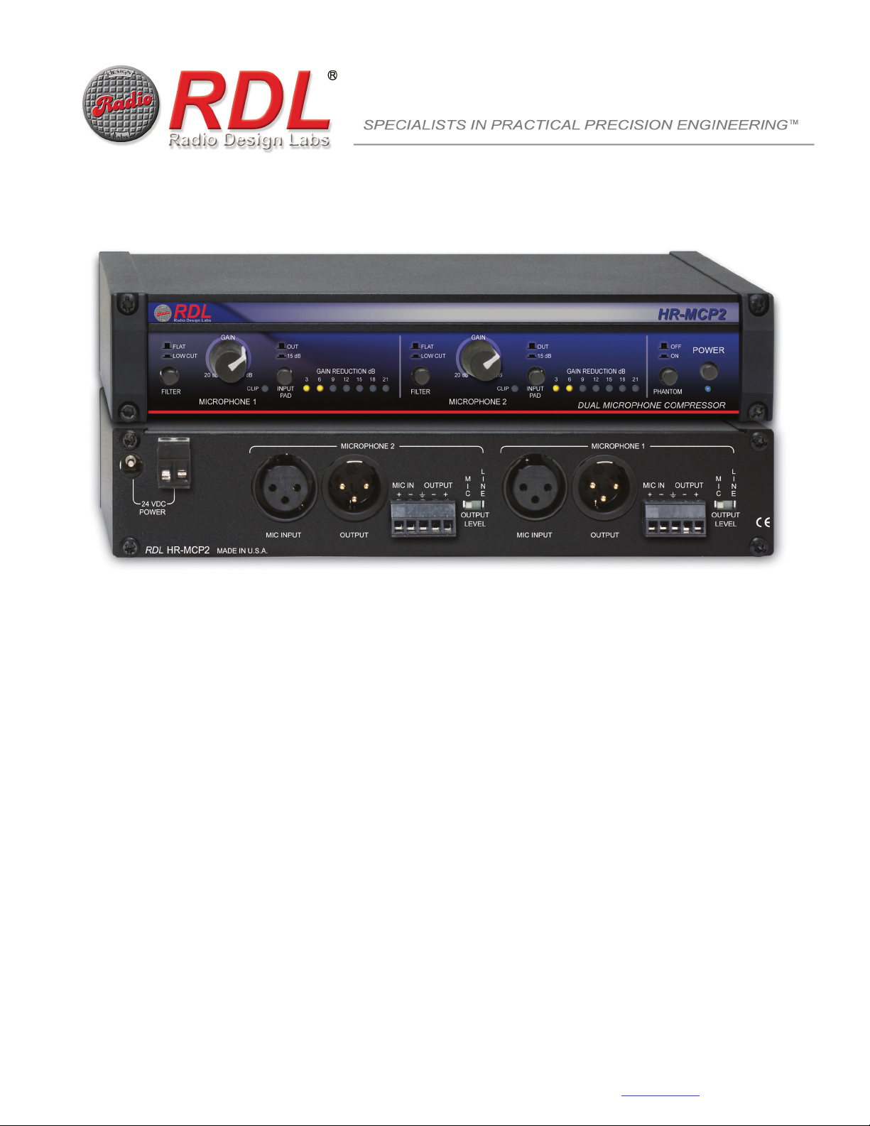
Model HR-MCP2
Dual Microphone Compressor
Two Independent Microphone Input Compression Channels
Produces Consistent Levels from Any Microphone
Installs Between Microphone and Mixer or Amplifier Mic Input
Line-Level Outputs Permit Operation as Dual Mic Preamp
Controls Overloads that Cause Distortion and Clipping
Balanced Mic Inputs on XLR and Detachable Terminal Block
Balanced Outputs on XLR and Detachable Terminal Block
The HR-MCP2 is an RDL HALF-RACK product, featuring an all metal chassis and the advanced circuitry for which RDL products are known. HALF-RACKs may be operated free-standing using
the included feet or may be conveniently rack mounted using available rack-mount adapters.
Each Output Allows Balanced or Unbalanced Connection
Independent Controls for Stereo or Dual Mono Operation
Front-Panel Gain Adjustment from 20 to 60 dB for Line Outputs
Switch-Selectable 15 dB Input Pads
Switch-selectable 48 Volt Phantom for Both Inputs
7 LED Gain Reduction Meter in 3 dB Increments per Channel
CLIP Indicators for Peaks 1 dB Below Clipping
APPLICATION: The HR-MCP2 is a dual channel microphone compressor that produces a consistent audio output level over wide variations
(up to 25 dB) in the microphone input level. Rear-panel switches allow setting each output to mic or line level. Each channel can therefore be
used as a mic-level in-line compressor or as a microphone preamplifier with compression. The unique circuit design preserves full studio-quality
low-noise performance at any gain setting. The HR-MCP2 is compatible with dynamic and condenser microphones. A front-panel switch is
provided to enable 48 Vdc phantom to both microphone inputs.
The HR-MCP2 is designed to hold average output levels constant without altering the sonic integrity of dynamic sources. Gain reduction is nearly
instantaneous for both expected and severe input overloads. Automatic release time adjustments result in nearly inaudible compression action
over the entire dynamic gain reduction range. The HR-MCP2 improves sound quality and intelligibility by producing consistent audio levels and
controlling overloads that produce distortion and clipping. It is ideally installed as the microphone preamplifier, or in-line between a microphone
and its associated mixer input, in on-air broadcast studios (announce mic, guest mics, crowd mics), voice-over studios, public address systems,
meeting rooms, public venues and commercial sound systems.
Each channel is equipped with a front-panel FILTER switch to enable or disable a 6 dB/octave low-cut filter with a -3 dB cutoff at 80 Hz. Each input
includes a front-panel INPUT PAD switch that allows the operator to attenuate the input signal by 15 dB prior to the input stage, increasing the
maximum input level from +5 dBu (attenuator out) to greater than +20 dBu. The GAIN control provides continuous adjustment between 20 dB and
60 dB (for the line-level output) to set the correct gain for normal microphone levels. A CLIP LED flashes if a signal peak is within 1 dB of clipping.
A seven LED metering string displays the instantaneous gain reduction in 3 dB increments.
The HR-MCP2 offers exceptional input headroom, wide flat frequency response and extremely low noise with very high common-mode signal
rejection. Total harmonic distortion and crosstalk are below the noise floor, allowing the HR-MCP2 to be operated as a stereo mic compressor or
preamplifier, or as two separate mono compressor/preamplifiers.
Each channel provides two balanced input and output formats on the rear panel: Detachable terminal block and XLR. Balanced inputs and
outputs may be wired unbalanced. The rear panel also provides a detachable terminal block and a power input jack to connect 24 Vdc power. The
HR-MCP2 is constructed in a durable half-rack-width shielded metal enclosure for free-standing use or for mounting in an RDL rack adapter,
available separately.
Wherever a dual-channel half-rack microphone compressor or preamplifier with compression is needed to provide superior audio clarity, user
adjustments, reliability, compactness and unsurpassed versatility and performance, the HR-MCP2 is the ideal choice. Combine the HR-MCP2
with other RDL products as part of a complete audio/video system.
RDL 659 6th St. Prescott, AZ., USA 86301 (928) 443-9391 FAX (928) 443-9392 www.rdlnet.com
Page 2
HALF-RACK
Model HR-MCP2
Dual Microphone Compressor
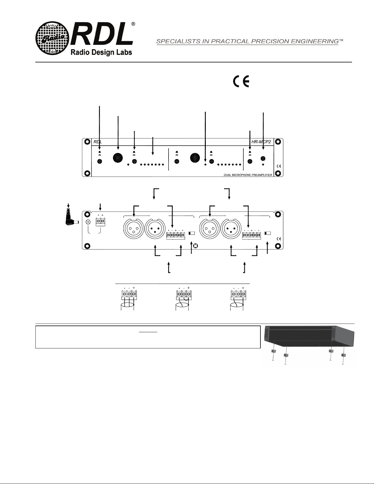
SET FILTER FOR FLAT RESPONSE
OR LOW-FREQUENCY CUT
ADJUST GAIN FOR DESIRED
AMOUNT OF GAIN REDUCTION
ENABLE PAD IF GAIN REDUCTION
IS EXCESSIVE WITH 20 dB GAIN
(NORMAL FOR SOME CONDENSER MICS)
GAIN REDUCTION METER
CLIP LED SHOULD
NEVER FLASH
Installation/Operation
BLUE LED INDICATES POWER IS ON
TURN ON MASTER PHANTOM
IF USING CONDENSER MICS
TURN ON POWER
(48 Vdc)
EN55103-1 E1-E5; EN55103-2 E1-E4
Typical Performance reflects product at publication tim e exclusive of
EMC data, if any, supplied with product. Specifications are subject to
change without notice.
PHANTOM
MIC IN OUTPUTOUTPUT
POWER
OFF
ON
L
M
I
ICN
E
OUTPUT
LEVEL
SET OUTPUT TO
MIC OR LINE LEVEL
(XLR AND TERMINAL BLOCK)
GAIN
FLAT
LOW CUT
CONNECT 24 VDC POWER TO
TERMINAL BLOCK OR JACK
24 VDC
POWER
MADE IN U.S.A.
HR-MCP2RDL
For free-standing operation, use the four provided machine screws to mount the feet to t he bottom of the module as shown, OR
Use the four provided machine screws to secure the module to an optional RDL mount, such as an HR-RA2 Rack Adapter.
TYPICAL PERFORMANCE
Inputs (4): XLR (2, 3 pin, rear panel,1=GND, 2+, 3-); detachable terminal block (2)
Input level (for uncompressed output): -60 dBu to -20 dBu (without input pad); -45 dBu to -5 dBu (with input pad)
Maximum Input Level: > +5 dBu (input pad disabled), +22 dBu (input pad enabled)
Input Impedance: > 1.5 k balanced
Phantom power: Selectable 48 V phantom (IEC 61938: 2013)
Input pad (2): 15 dB nominal (1 per input channel)
Outputs (4): XLR (2, 3 pin, rear panel,1=GND, 2+, 3-); detachable terminal block (2)
Output level: Mic: -45 dBu (nominal, into 600 Ohms)
Line: +4 dBu balanced (nominal, dynamic audio source), +1 dBu balanced (nominal, sine-wave producing 3 dB compression)
Output Impedance: 150 balanced
Channels: 2 (1 and 2; may be used for stereo or as two separate mono channels)
Gain Trim (2): 20 dB to 60 dB (line-level output; front panel adjustable; one for each channel)
Frequency Response: 10 Hz to 25 kHz (+/- 0.5 dB, FLAT); -3 dB @ 80 Hz (LOW-CUT FILTER enabled)
THD: Below noise floor (3 dB compression)
CMRR: > 70 dB (50 Hz to 5 kHz)
Residual Noise (below rated output level): < -85 dB (20 Hz to 20 kHz, 40 dB gain, without compression, 150 source)
< -70 dB (20 Hz to 20 kHz, 60 dB gain, without compression, 150 source)
Crosstalk: Below noise floor
Indicators (17): POWER LED (blue), GAIN REDUCTION (7 per channel, yellow, 3, 6, 9, 12, 15, 18, 21 dB), CLIP (2, red)
Power Requirement: 24 Vdc @ 200 mA (230 mA with phantom), Ground-referenced
Mounting: Rack-mount using optional rack adapters such as HR-RA2; or operate free-standing (feet included)
Dimensions: Height: 1.7 in, 4.3 cm; Length: 8.6 in, 20.6 cm; Depth: 4.59 in, 11.66 cm
(SHIELD OPTIONAL FOR LINE OUTPUT)
OUT
15 dB
GAIN REDUCTION dB
12 15 18 21 21181512
60 dB20 dB
BALANCED
369
PAD PAD
XLR OR
TERMINAL BLOCK
MICROPHONE 2
MOUNTING
FILTER
CONNECT MICROPHONES TO THE MIC INPUTS
XLR OR
TERMINAL BLOCK
CONNECT OUTPUTS TO OTHER EQUIPMENT INPUTS
TERMINAL BLOCK WIRING
UNBALANCED
GAIN
FLAT
LOW CUT
20 dB 60 dB
CLIPCLIP
MICROPHONE 2MICROPHONE 1
L
M
I
NCI
E
OUTPUT
LEVEL
OUTPUTMIC INOUTPUT
SET OUTPUT TO
MIC OR LINE LEVEL
(XLR AND TERMINAL BLOCK)
INPUT OUTPUTINPUT OR OUTPUT
INPUTINPUT FILTER
MIC INPUTMIC INPUT
OUT
15 dB
GAIN REDUCTION dB
963
XLR OR
TERMINAL BLOCK
MICROPHONE 1
XLR OR
TERMINAL BLOCK
UNBALANCED
891-3440A
Radio Design Labs Technical Support Centers
U.S.A. (800) 933-1780, (928) 778-3554; Fax: (928) 778-3506
Europe [NH Amsterdam] (++31) 20-6238 983; Fax: (++31) 20-6225-287
 Loading...