

Page 1
ACCESSORIES
HD-WM1 & HD-WM2
HD SERIES WALL MOUNT
Installation/Operation
EN55103-1 E1-E5; EN55103-2 E1-E4
Typical Performance reflects product at publication time
exclusive of EMC data, if any, supplied with product.
Specifications are subject to change without notice.
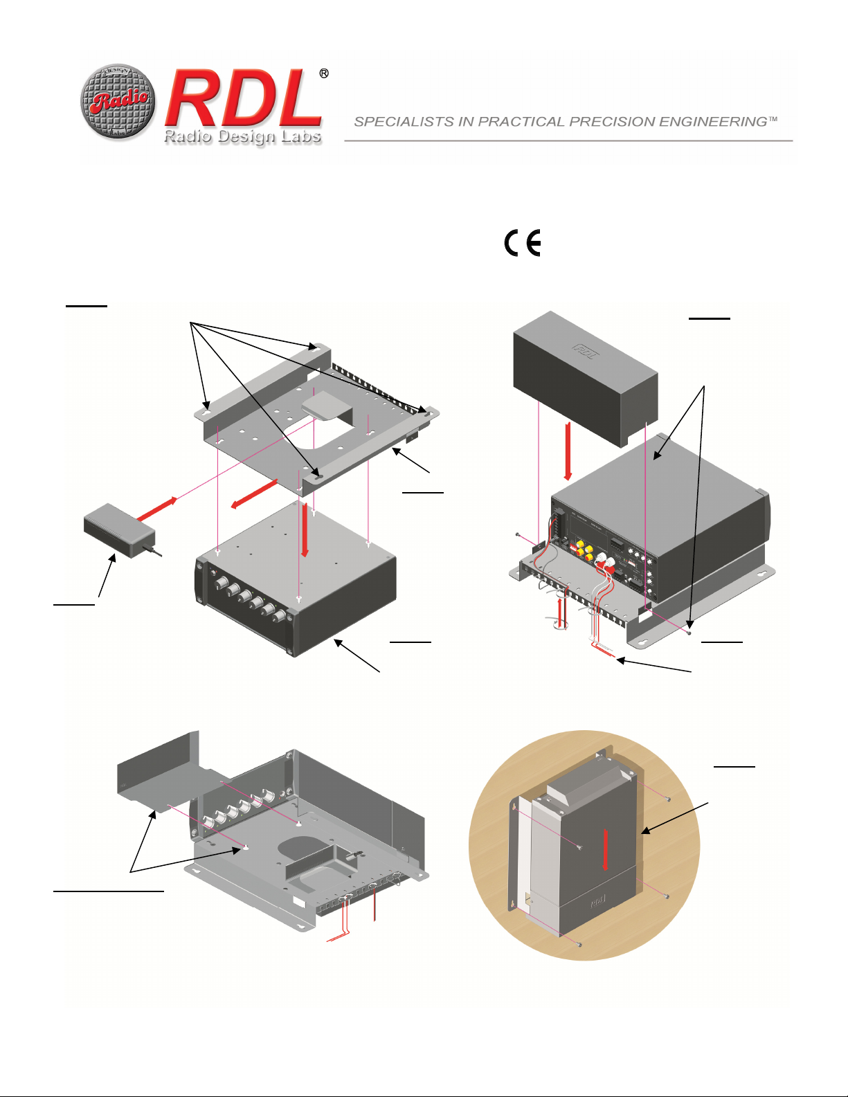
Step 1
Use the bracket to mark
the mounting screw
locations. Start the
installer-provided
mounting screws, leaving
sufficient clearance
behind the screw heads to
permit the bracket to slide
behind the heads.
The installation hardware
must be rated to safely
secure the combined weight
of the bracket and the
associated HD product.
Step 6
Start the two wire-cover
screws (included).
Slide the cover into
position and secure by
tightening the screws.
Note:
Step 3
Lower the bracket over
the screws. Slide the
bracket forward and
tighten the screws.
Step 4
Snap the power supply
into position under the
retention clip.
Step 2
Place the HD product on a flat
horizontal surface with the
bottom of the product facing
upward. Remove the screws
that secure the four feet.
Reinstall the four screws,
without the feet, leaving the
screws loose.
Step 5
Connect the power,
input and output
wiring, securing the
wires to the
mounting bracket
tabs using installerprovided tie wraps.
Step 8
Slide the bracket
over the wall
mounting screws
and tighten the
Step 7 (Optional)
Loosen the two security
cover mounting screws,
slide the HD-ASC1
(available separately)
onto the front of the unit
and tighten the screws to
secure the cover.
screws to secure
the bracket.
The installation
hardware must be
rated to safely
secure the combined
weight of the bracket
and the associated
HD product.
Note:
891-3435
Radio Design Labs Technical Support Centers
U.S.A. (800) 933-1780, (928) 778-3554; Fax: (928) 778-3506
Europe [NH Amsterdam] (++31) 20-6238 983; Fax: (++31) 20-6225-287
 Loading...