

Page 1
FLAT-PAK™ SERIES
Model FP-MX3R
Remote Controlled
Line-Level Mixer
• 3-Channel Remote-Controlled Audio Mixer
• VCA Level Control for Each Input
• Balanced or Unbalanced Inputs
• Balanced and Unbalanced Outputs
• Two Mono Unbalanced Outputs to Feed Stereo Amplifier
• Inputs and Outputs on Detachable Connectors
• Twisted Pair Interconnection to Remote Control
• Directly Controlled by RDL Remote Controls
• Two and Three Channel Remote Controls Available
• Fixed Level Possible for Input 3 if Two Channel Remote Used
• Paging Source May Connect to Input 3
• Front-Panel Gain Trim for Standard Audio Line Levels
• Dual-LED VU Meter Displays Mixer Output Level
• Audio Presence Detector Controls Open-Collector Outputs
• Detector Outputs Intended to Enable Power Amplifiers or System Power
• Energy Savings Possible Using Detector Outputs
• Selectable 10 or 20 Minute Detector Release Delay
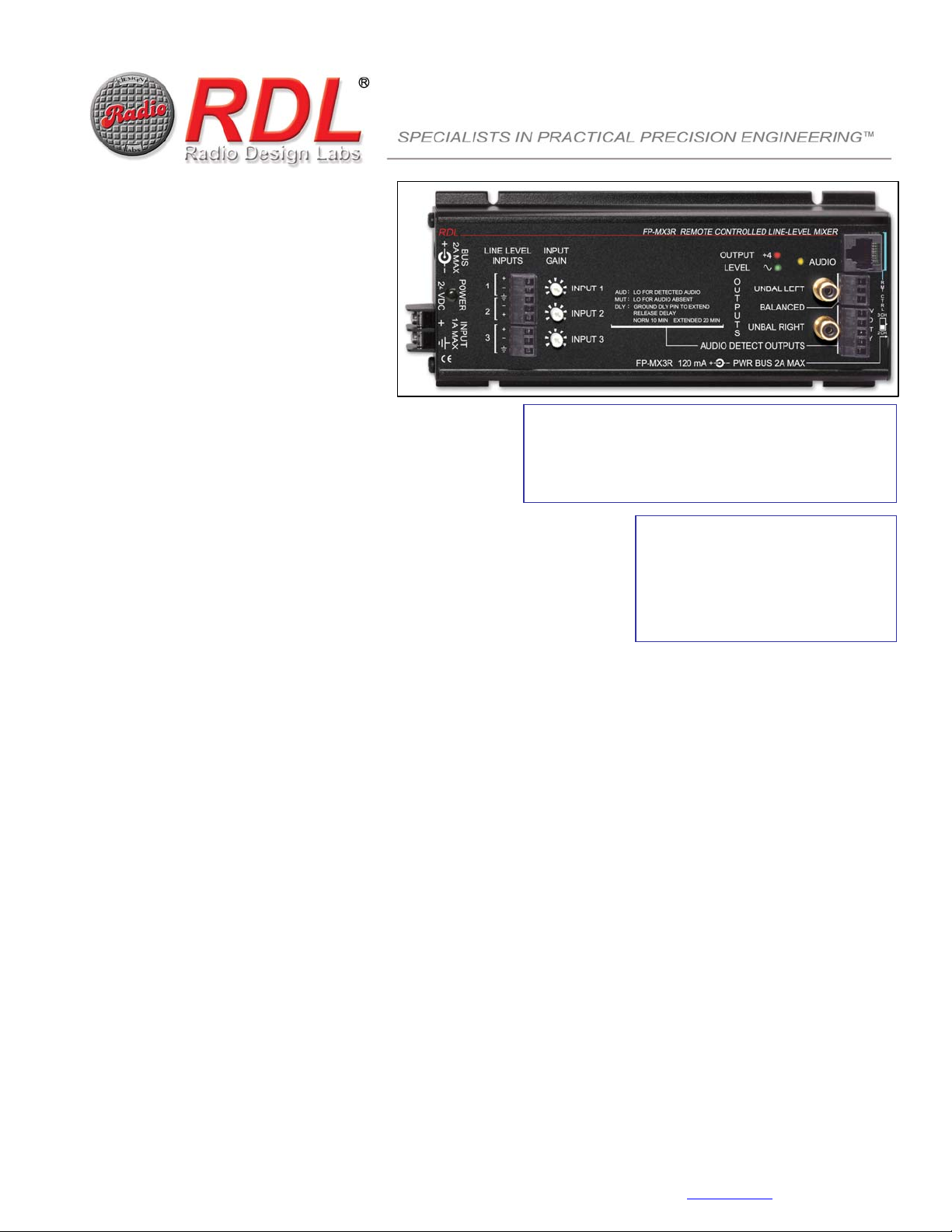
The FP-MX3R is a mono audio mixer in the convenient line of FLAT-PAK products, featuring the superior engineering and components common to
RDL products. The FP-MX3R may be rack or surface mounted with optional FLAT-PAK series accessories. The FP-MX3R gives you the
advantages of a quality audio mixer with the added convenience of remote control!
The FP-MX3R is the ideal choice where a user-accessible mixer must control the volume of multiple sources. The mixer accepts
balanced or unbalanced audio sources through a detachable terminal block. FP-MX3R outputs are provided in balanced and
unbalanced formats. Two unbalanced outputs are available to feed the mono mixer output to a stereo amplifier input. Remote
control of the mixer allows audio signals to be kept at a single equipment location. Audio is mixed by VCA circuits that are
adjusted by control signals from the remote control.
Each input is equipped with an INPUT GAIN trimmer to set the proper operating level for each source. A standard RDL dual-LED
VU meter provides visual indication of the output level from the mixer. Each input is normally adjusted to produce +4 dBu on the
VU meter when the corresponding remote control channel is adjusted to maximum. This assures ample headroom at all normal
operating levels. The mixer output is mono. The output is available on a single balanced detachable terminal block or on two
unbalanced RCA jacks intended to connect directly to the stereo input of a power amplifier.
The AUDIO LED illuminates whenever audio is present at the output of the mixer, defined as greater than 35 dB below +4 dBu.
This threshold triggers the AUDIO DETECT OUTPUTS. Two open collectors are provided on a detachable terminal block. One of
these terminals switches low when audio is present, and may be used to switch amplifiers or other system components on. The
other terminal is pulled low when audio is not present. It is intended for muting the digital carrier of power amplifiers equipped for
remote muting. Either of these terminals may be used to trigger a variety of other RDL modules or OEM equipment. The use of
these terminals to shut down unused equipment can produce effective system energy and cost savings. These control terminals
normally remain triggered for 10 minutes after audio is absent. The delay can be increased to 20 minutes using a ground jumper
on the terminal block.
The mixer levels are set by RDL remote controls that connect directly to the FP-MX3R through an RJ45 jack using standard
twisted pair cable. The control ports on the mixer and remote controls are color-coded light blue to distinguish them from other
twisted pair jacks. The mixer provides power to the remote control. Either a two or three channel remote control may be used. If
remote mixing of only two channels is needed, a two channel remote may be used. INPUT 3 becomes the input channel that is
not remotely controlled. This input may be left active at a level set on the corresponding INPUT GAIN control, typically for a paging
or music source, or may be disabled by a switch set during installation. If the cable connected to the remote control becomes
disconnected, the mixer output mutes.
Wherever it is desirable to keep audio signal sources at an equipment location while providing compact, high quality user mixing
controls, the FP-MX3R is the ideal choice. Use an FP-MX3R and its associated remote control individually or combine them with
other RDL products as part of a complete audio/video system.
ASSOCIATED REMOTE CONTROL EXAMPLES:
► D-RC2 and DS-RC2 Two-channel remote controls
► D-RC2M and DS-RC2M Two-channel remote controls with muting
► D-RC3 and DS-RC3 Three-channel remote controls
► D-RC3M and DS-RC3M Three-channel remote controls with muting
TYPICAL APPLICATIONS:
► Meeting Rooms
► Boardrooms
► Classrooms
► Restaurant or Residential Patios
► Retail Stores
► Offices
RDL • 659 N. 6th St. • Prescott, AZ., USA 86301 • (928) 443-9391 • FAX (928) 443-9392 • www.rdlnet.com
Page 2
FLAT-PAK
™
SERIES
Model FP-MX3R
Remote Controlled
Line-Level Mixer
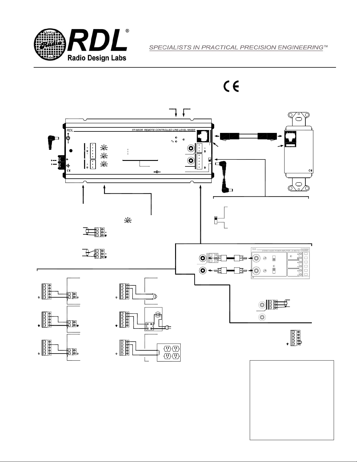
Audio output level from the mixer is shown on dual-LED VU meter
2A MAX
BUS
LINE LEVEL
POWER
24 VDC
OR
24 VDC
POWER
SOURCE
Connect each input from a balanced or
BALANCED SOURCE
UNBALANCED SOURCE
1
2
1A MAX
INPUT
3
unbalanced audio source.
AUDIO DETECT / CONTROL OUTPUT CONNECTIONS
OEM AMPLIFIER WITH
+24V
+24V
AUD
MUT
+24V
AUD
MUT
AUD
MUT
DLY
DLY
DLY
EXTERNAL "MUTE" TERMINAL
(POWER DOWN AMPLIFIER
WHEN AUDIO NOT PRESENT)
MUTE / DISABLE AMPLIFIER
POWER OUTLET WITH
EXTERNAL CONTROL
TERMINALS TO TURN SYSTEM
AND / OR AMPLIFIER ON
GROUND TO ENABLE OUTLET
TRIGGER ANY RDL MODULE
WHEN AUDIO IS PRESENT
SLAVE
INPUTS
+
+
+
INPUT
GAIN
+
+
INPUT 1
INPUT 2
INPUT 3
+24V
AUD
MUT
DLY
+24V
AUD
MUT
DLY
+24V
AUD
MUT
DLY
OUTPUT
LEVEL
O
UNBAL LEFT
AUD LO FOR DETECTED AUDIO
MUT LO FOR AUDIO ABSENT
DLY GROUND DLY PIN TO EXTEND
RELEASE DELAY
NORM 10 MIN EXTENDED 20 MIN
U
T
P
BALANCED
U
T
UNBAL RIGHT
S
AUDIO DETECT OUTPUTS
FP-MX3R 120 mA+4PWR BUS 2A MAX
With the corresponding input channel set to
maximum level on the remote control, set the
front-panel INPUT GAIN control for a proper reading
on the dual-LED VU meter (maximum green LED
intensity with minimum red LED activity)
UNBAL RIGHT
EXTERNAL LAMP OR LED
CONNECTION TO INDICATE
AUDIO PRESENT / SYSTEM
ACTIVE
24 VDC
LAMP
SOLID STATE
SOLID STATE
RELAY MODULE
RELAY MODULE
MAINS TO
EQUIPMENT
ACTIVATE A CONTROL RELAY
WHEN AUDIO IS PRESENT
24VDC RELAY COIL
Installation/Operation
AUDIO LED glows when audio is detected. The "audio detect" outputs are triggered by
the detected audio and remain active 10 or 20 minutes following a loss of audio.
AUDIO
+
R
Mixing remote control jacks are color-coded light blue
M
T
C
T
R
L
+24V
3 CH
AUD
MUT
2 CH
DLY
SWITCH LOCATED IN THE MODULE END PLATE ACTIVATES OR
DE-ACTIVATES INPUT PAIR C IF A 2 CHANNEL REMOTE CONTROL IS USED
3 CH
2 CH
EN55103-1 E1-E5; EN55103-2 E1-E4
Typical Performance reflects product at public ation time
exclusive of EMC data, if any, supplied with product.
Specifications are subject to change without notice.
NOTE: POWER FOR THE REMOTE
CONTROL IS PROVIDED FROM THE
MIXER THROUGH THE C ABLE
TWISTED
PAIR CABLE
Power to Additional
Flat-Pak Modules, Total
Current Not to Exceed 2 A or
Available Supply Current
SET TO 3 CHANNEL REMOTE CONTROL POSITION IF:
1) A 3 CHANNEL REMOTE CONTROL IS CONNECTED, OR
2) A 2 CHANNEL REMOTE CONTROL IS CONNECTED AND THE
THIRD MIXER INPUT (PAIR C) WILL NOT BE USED
(IN THIS POSITION, THE PAIR C INPUT IS DISABLED)
SET TO 2 CHANNEL REMOTE CONTROL POSITION IF:
A 2 CHANNEL REMOTE CONTROL IS CONNECTED AND THE
THIRD MIXER INPUT (PAIR C) WILL BE USED WITH
A LOCAL INPUT NOT RE QUIRING GAIN ADJUSTMENT
(EXAMPLE: PAGING INPUT)
AUDIO OUTPUT CONNECTIONS
UNBAL LEFT
BALANCED
INPUTSLGAIN
UNBALANCED
Connect the balanced output to a balanced amplifier input, or
connect the left and right unbalanced RCA jacks to the L and R
unbalanced inputs of an amplifier. (Note: The unbalanced
outputs are mono; the dual jacks are provided for installation
NOTE: THE 24 VDC OUTPUT
TERMINAL IS PROTECTED BY
AN AUTOMATICALLY
RESETTING FUSE.
THE "AUD" AND "MUT" OUTPUT CONTROL TERMINALS
SWITCH UPON DETECTION OF A UDIO ("AUD" SWITCHES
LOW; "MUT" RELE ASES) AT THE MIXER OUTPUT AND
REMAIN IN THAT STATE UNTIL THE AUDIO HAS BEEN
ABSENT FOR 10 MINUTES AT WHICH TIME THEY TOGGLE
TO THE OPPOSITE STATE ("MUT" SWITCHES LOW; "AUD"
RELEASES). THE DELAY MAY BE EXTENDED FROM 10 TO
20 MNUTES BY INSTALLING THE JUMPER AS SHOWN
BETWEEN "DLY" TERMINAL AND GROUND.
UNBAL LEFT
BALANCED
UNBAL RIGHT
R
INPUT MODE
SUMMED MONO
STEREO
COMPRESSOR/LIMITER
THRESHOLD
4 OHMS (2 x 15W)
8 OHMS (2 x 20W)
OUTPUT IMPEDANCE
convenience.)
CONTROL
D-RC2
D-RC2M
D-RC3
D-RC3M
24 VDC
POWER
LEFT
OUTPUT
RIGHT
OUTPUT
BALANCED OUTPUT
BALANCED
+24V
AUD
MUT
DLY
TYPICAL PERFORMANCE
Inputs (3): Balanced or unbalanced line level
Input Connections: Detachable Terminal Blocks
Input Signal Range: -20 dBV to +8 dBu, adjustable (for +4 dBu output)
Outputs (3): 150 Ω balanced; 1 kΩ unbalanced (2)
Output Connections: Detachable Terminal Block (balanced); RCA Phono Jack s (unbalanced)
Output Level: +4 dBu balanced, -10 dBV unbalanced
Frequency Response: 20 Hz to 20 kHz (+/- 0.25 dB)
THD+N: < 0.05% (20 Hz to 20 kHz); <0.02% (1 kHz)
Noise below +4 dBu: < -100 dB (all channels off); <-75 dB (any channel on); <-70 dB (all channels on)
Headroom above +4 dBu: > 18 dB
CMRR: > 50 dB (50 Hz to 150 Hz)
VCA attenuation: >90 dB (each input, remote control volume off)
Indicators (3): Dual-LED VU meter (2); Audio present (threshold = 35 dB below +4 dBu output)
Power Connections (3): Terminal block; dc power jack (2)
Power Requirement: 24 Vdc @ 120 mA plus connected c ontrol output loads, if any
Overall Dimensions: Height: 1.42 in 3.61 cm
Width: 3.25 in. 8.26 cm
Length: 8.14 in. 20.68 cm
Radio Design Labs Technical Support Centers
U.S.A. (800) 933-1780, (928) 778-3554; Fax: (928) 778-3506
891-2140A
Europe [NH Amsterdam] (++31) 20-6238 983; Fax: (++31) 20-6225-287
NOTE: This equipment has been tested and found to
comply with the limits for a Class B digital device, pursuant
to part 15 of the FCC Rule. These limits ar e designed to
provide reasonable protection against harmful interfer ence
in a residential installation. The equipment generates,
uses and can radiate radio frequency energy and, if not
installed and used in accordance with the instructions,
may cause harmful interference to radio communications .
However, there is no guarantee that interference will not
occur in a particular installation. If this equipment does
cause harmful interference to radio or televis ion reception,
which can be determined by turning the equipment off an
on, the user is encouraged to try to correct the
interference by one or more of the following measures:
• Reorient or relocate the receiving antenna
• Increase the separation between the equipment
and receiver
• Connect the equipment into an outlet on a circuit
different from that which the receiver is
connected.
• Consult the dealer or an experienced radio/TV
technician for help.
 Loading...