

Page 1

™
FLAT-PAK
Model FP-DFC2
SERIES
Digital Format Converter
Conversion from SPDIF to AES/EBU
Conversion from AES-3ID to AES/EBU
Exclusive
Sure-Lok
™
Auto-Recovery
Automatic Sample Rate Detection
Coaxial or Optical Input
Valid Signal LOCK LED Indicator
Transformer Isolated Output
Full Operation up to 24 bit / 192 kHz
Cabinet, Shelf or Rack Mounting
The FP-DFC2 is part of the group of versatile FLAT-PAK products from Radio Design Labs. The unique FLAT-PAK case can be directly screwed
or bolted to cabinets or shelves. Optionally available rack-mounting accessories permit single or multiple FLAT-PAK module mounting.
All FLAT-PAK modules are supplied with a power interconnect cable for daisy-chaining multiple modules from a single power supply.
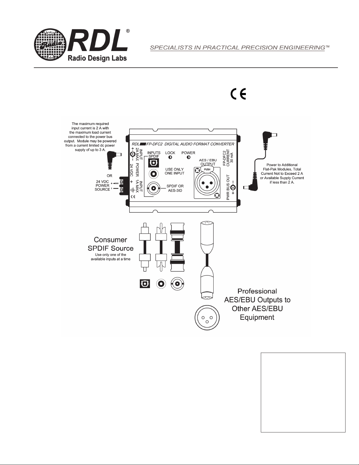
APPLICATION: The FP-DFC2 is the ideal choice in many applications where an SPDIF source must be connected to
AES/EBU professional digital audio equipment. The digital input and output connections are made on the top panel jacks.
Power connections are made using either the full-size barrier block terminals or a dc power jack located in an end panel. A
second dc power jack is provided on the other end panel for connecting additional Flat-Pak modules.
Three jacks are provided for SPDIF inputs: Phono, BNC and Optical. The BNC jack can also receive an AES-3ID signal.
Any one of these input jacks may be used. The AES/EBU output connects through an XLR jack. The electrical output is
transformer isolated. The input signal is decoded and reassembled in the AES/EBU format. All header information
common to both SPDIF and AES/EBU standards is inserted in the output data stream. An LED indicator is illuminated when
a valid, locked digital input signal is being converted to the output.
A frequent problem encountered with consumer and professional quality digital audio equipment is unpredictable latch-up
when digital signals are switched or connected to a digital input.
FP-DFC2 monitors the most frequent causes of latch-up and reinitiates digital signal lock, bringing a new higher level of
stability to digital audio format conversion under the variety of conditions encountered in professional environments.
The FP-DFC2 has several unique features which set it apart from other professional converter devices: 1] All header
information common to both formats is provided in the AES/EBU output, not just selected information. 2] Anti-latch-up
control circuits provide highly stable operation. 3] The electrical output is transformer isolated. 4] The FP-DFC2’s design
permits it to be easily mounted, particularly in confined spaces and in various locations in equipment racks.
Wherever convenient, economical, high performance digital audio format conversion is required, the FP-DFC2 is the ideal
choice. Use the FP-DFC2 individually, or combine it with other RDL products as part of a complete audio/video system.
Sure-Lok
™ auto-recovery circuitry unique to the
RDL 659 6th St. Prescott, AZ., USA 86301 (928) 443-9391 FAX (928) 443-9392 www.rdlnet.com
Page 2
™
FLAT-PAK
Model FP-DFC2
SERIES
Installation/Operation
Declaration of Conformity available from rdlnet.com.
Sole EMC specifications provided on product package.
Specifications are subject to change without notice.
Digital Format Converter
TYPICAL PERFORMANCE
Inputs (3): 75 , SPDIF (phono or BNC) or optical, AES-3ID (BNC)
Output: AES/EBU balanced XLR transformer isolated
Sample Rate: 32 kHz to 192 kHz
Resolution: 16 to 24 bits
Standards: IEC958, SPDIF and EIAJCP340/1201; AES3-1992
Amendment 3-1999
Indicators (2): LED LOCK indicator (locked to a valid signal); POWER
Power Requirement: 24 Vdc @ 30 mA, Ground-Referenced
Overall Dimensions: Height: 1.34 in. 3.40 cm
Width: 3.25 in. 8.26 cm
Length: 4.81 in. 12.22 cm
Radio Design Labs Technical Support Centers
U.S.A. (800) 933-1780, (928) 778-3554; Fax: (928) 778-3506
891-2135B
Europe [NH Amsterdam] (++31) 20-6238 983; Fax: (++31) 20-6225-287
NOTE: This equipment has been tested and found to
comply with the limits for a Class B digital device, pursuant
to part 15 of the FCC Rule. These limits ar e designed to
provide reasonable protection against harmful interfer ence
in a residential installation. The equipment generates,
uses and can radiate radio frequency energy and, if not
installed and used in accordance with the instructions,
may cause harmful interference to radio communications .
However, there is no guarantee that interference will not
occur in a particular installation. If this equipment does
cause harmful interference to radio or televis ion reception,
which can be determined by turning the equipment off an
on, the user is encouraged to try to correct the
interference by one or more of the following measures:
Reorient or relocate the receiving antenna
Increase the separation between the equipment
and receiver
Connect the equipment into an outlet on a circuit
different from that which the receiver is
connected.
Consult the dealer or an experienced radio/TV
technician for help.
 Loading...