

Page 1
x
RACK-UP
ma
®
SERIES
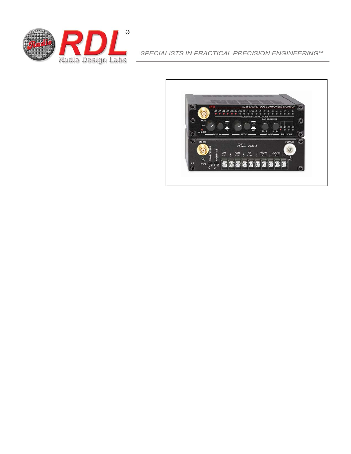
Model ACM-3
Synchronous AM Noise Monitor
ANYWHERE YOU NEED...
• Maintained Clarity
• Maximized Loudness
• Maximized Stereo Separation
• Reduced Subcarrier Crosstalk
• Positive Control Over Multipath Artifacts
• Assured Consistency in Signal Coverage
• Bright 20-LED Metering String
• Switch Selectable Signal Filtering
• Wideband, 75 µs, and High-Pass Filtering
•
Programmable Alarm with Remote Output
•
Continuous-Reading DC Output of AM Noise
•
Transmitter Power DC Remote Metering
Introduction
The ACM-3 is a test instrument which monitors the amplitude component present on frequency modulated carriers. The AM component is
representative of bandwidth characteristics in the transmission system. The technology of significant synchronous AM noise monitoring was pioneered
by Radio Design Labs, the originator of AM noise monitors for FM radio and television aural transmission.
In theory, FM carriers are of a constant amplitude over the range of frequencies they swing above and below carrier frequency. In practice, however, the
amplitude is compromised by a variety of factors. These amplitude modulations of the carrier comprise AM noise. Two general varieties of AM noise are
considered: 1] Noise induced by power supplies and blower vibrations (noise not synchronized to the applied modulation); 2] AM Noise resulting from
frequency modulation of the carrier (noise synchronized to the applied modulation, hence “synchronous” AM noise). This noise is produced by passband
amplitude and phase non-linearities in the rf transmission system. Consequently interstage matching is a significant contributor to AM noise as is the
phase delay inherent in high gain amplifier stages. These factors combine to produce an operating passband for the transmission system.
As the carrier frequency shifts with modulation, the carrier frequency (or actually resultant sidebands) at a given instant will fall on some point of the
skirts of a tuned circuit. If the bandwidth of the tuned circuit is sufficient, the amplitude of the FM carrier will remain constant, or so nearly constant that
the amplitude variation is not significant. If there is any roll-off to the passband of the tuned circuit, the carrier amplitude will change with shifting
frequency resulting in amplitude modulation. The FM transmission system considered as a whole will exhibit different passband characteristics above
the carrier frequency as it does below that frequency. Therefore the sidebands, both upper and lower, generated by a single cycle of modulation will be
unequally attenuated. The resulting disparity produces a difference in carrier amplitude which can be demodulated in an FM receiver. The phase
relationship between this demodulated signal and the recovered frequency modulation produces an audible mix which, in stereo systems, is then further
demodulated into left and right. It is easily seen how these effects will degrade both stereo and audio receiver performance. The incoming amplitude
modulations are often further affected by automatic gain control circuits in the receiver.
EFFECTS OF AM NOISE
In the FM receiver, signal integrity is dependent on accurate demodulation of several signals, including both amplitude and often frequency modulated
subcarriers which are typically at least 20 dB below full carrier. Shifts in amplitude can therefore produce marked effects on the subcarrier performance,
as intermodulation distortion produces substantial baseband noise in the receiver. This is first usually noticed in degraded stereophonic performance
resulting from multipath distortion of the received signal. Observations of the station signal on analog tuners frequently yields an actual narrowing of the
occupied width on the dial, even with fairly minor increases in AM noise. AM noise levels in the transmission system can produce noise in the receiver
similar to the AM noise actually generated by multipath itself. These effects are detrimental to SCA operation, as crosstalk from the main channel
becomes objectionable. These same effects degenerate stereo performance. Even moderate levels of multipath which might otherwise not be
objectionable, have been observed to become severe when compounded with transmission system AM noise. Although keeping close monitoring and
control over variations in AM noise in the transmitter cannot eliminate multipath distortion which occurs after the signal leaves the antenna, minimizing
transmitter AM noise keeps the overall multipath artifacts at the very minimum possible in the receiver. Close control of transmitter AM noise makes
possible optimum performance of both SCA and stereophonic transmission.
SIGNIFICANT SYNCHRONOUS AM NOISE
Amplitude modulations which are of both sufficient amplitude and pulse width to produce any receiver artifacts are revealed by the various sampling
bandwidth and time constants of analysis circuits in the ACM-3. This significant synchronous noise component is displayed on a
damped-decay string display.
fast-rise,
Page 2
AM NOISE MONITORING
As tubes slowly age, and temperatures change, the significant synchronous AM noise level in the transmission system changes. Very low AM noise
levels will not materially affect receivers. However, as AM noise increases, it will exceed the threshold above which performance degradation is noticed
in SCA or stereo operation. Good engineering of consistent FM transmission requires close control of AM noise, as well as the facility to distinguish
between signal inconsistencies produced by AM noise and those resulting from propagation anomalies. To accomplish this, the engineer must have
immediate access to AM noise readings. The ACM-3 constantly monitors the AM noise levels and provides an alarm output which can be used to alert
the duty operator when the AM noise has exceeded the value set by the engine er. B y setting this alarm threshold se veral dB belo w t he point wher e A M
effects are determined to be objectionable, a transmitter trip can be scheduled and the AM level can be controlled prior to the statio n signal suffering
any adverse effects. The ACM-3 also provides a calibrated remote control output permitting the AM noise level to be read from the studio location at all
times.
SAMPLING
Samples of FM carriers are often available at different points in the transmission system. The only place to obtain an rf sample appropriate for AM noise
measurements is AFTER THE LOW-PASS (or other bandwidth-limiting) FILTER. Monitor jacks in the PA cavity area of a transmitter are totally useless
for AM noise measurements. These jacks provide rf containing harmonic content which renders the AM noise readings totally erroneous. The
DCF-100MB supplied with the ACM-3 is to be connected to a DIRECTIONAL sampler situated in a metering line section at the point nearest the
antenna feed line. Samplers are available in two general types: Capacitive samplers and Directional samplers. It is a sampler of the directional type
which must be used for AM noise readings. Capacitive samplers typically have a screw adjustment on them to set rf pickup, and they sample both
forward and reflected waves. For AM noise measurements, only the forward wave must be used. It is imperative that the DCF-100MB be connected
physically RIGHT AT THE SAMPLER JACK. Do not connect a length of cable between the sampler and the DCF-100MB input, as even the slightest
VSWR in this cable can substantially impair the accuracy of your readings. Often a station will have a line section already installed just prior to the
antenna feed line for power monitoring purposes. One of these sample ports is suitable for installing a directional sampler to feed the DCF-100MB.
Often, however, one or both of these ports is being used to feed either remote cont rol readings or to detect transmitter power for automatic switchover
or alerts. If the sampler for the DCF-100MB is displacing a metering slug normally used to supply a forward power indication, note that the ACM-3 has a
DC power metering output. This output can be used for remote power metering, or can be resistively divided down to a usable sample level for other
switching purposes. This ACM-3 output is independent of the front-panel calibrate control, and is buffered against external load effects.
Installation: READ AND UNDERSTAND THIS BEFORE INSTALLING!!!
Many hookups within a broadcast facility can be done merely to make it work, even though they may not be exactly done right. THIS IS NOT THE CASE
WITH AM NOISE SAMPLES. If you do not begin with an accurate sample, your ACM-3 may still register readings, ho wever, those readings can be
grossly inaccurate, leading you to make corresponding adjustments to your transmitter that have an adverse effect on your signal or efficiency.
Obtaining a correct sample is not difficult, but the importance of doing it right cannot be emphasized enough. Once a correct sample is established, you
can have years of optimum service from your transmitter without giving the sample port a second thought. If you have not yet read the preceding
section, SAMPLING, read it now, as it details all the pertinent considerations in establishing an accurate sample point. Plugging the DCF-100MB into
just any BNC rf sample may not be appropriate. If the sample contains harmonic energy (as in PA rf loop samples, or any pre-harmonic-filter samples),
or if it contains reflected power, this additional material can add or subtract from your fundamental carrier rf voltage, thereby generating AM noise in
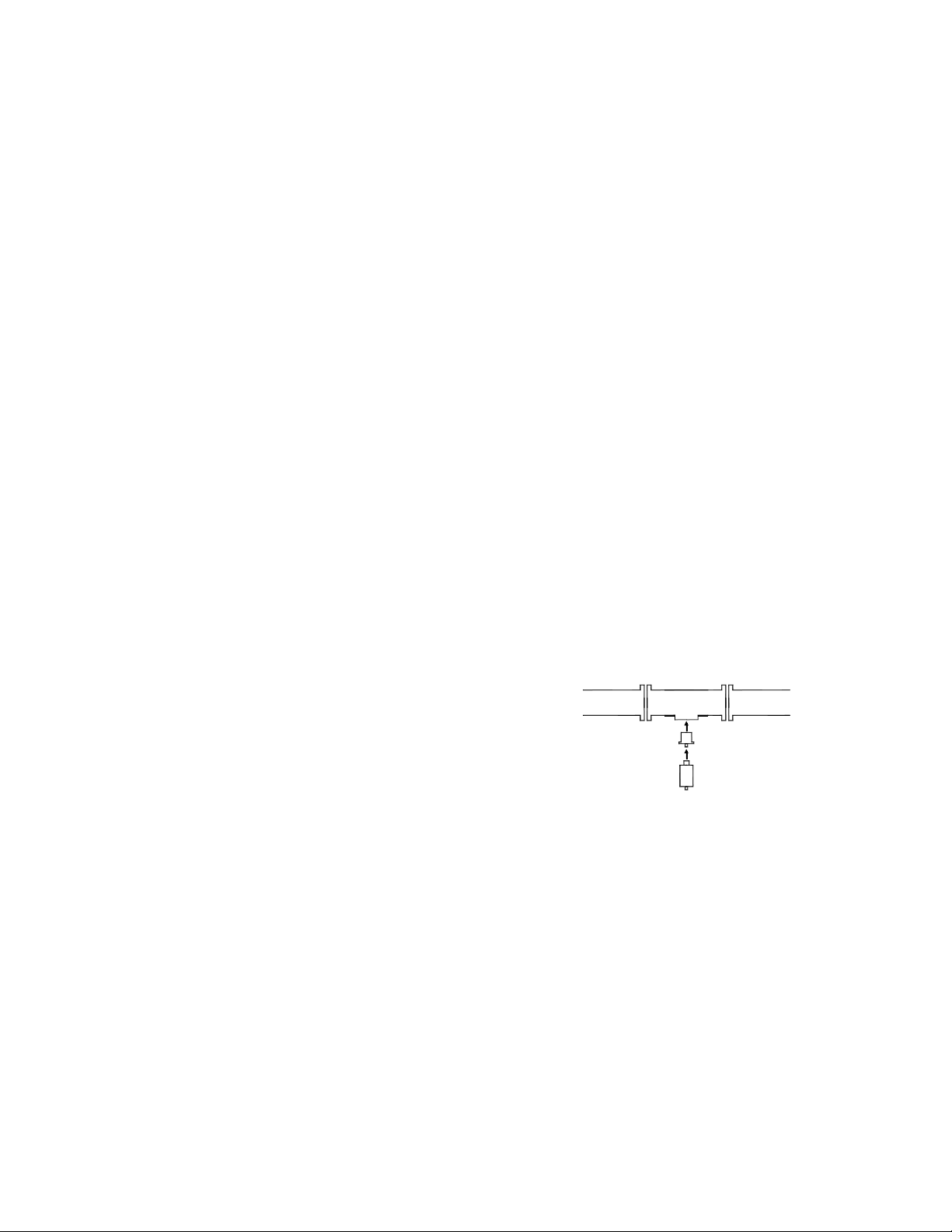
your sample. This problem is avoided by the use of a DIRECTIONAL (forward) sample. Many, if not most, FM stat ions have a line section with slug
ports for power metering. An excellent method of obtaining a forward sample suitable for AM noise metering is to replace a slug with a directional rf
sampler, as shown in the drawing.
The attenuation of the sampler must produce an rf sample voltage within the operating input range of the DCF-100MB. The following table lists the
appropriate attenuation levels for common power ranges. Part numbers are shown for samplers produced by Coaxial Dynamics (Cleveland, Ohio).
These samplers are specifically designed for use with the ACM-3.
Transmitter Power Line Section Attenuation Sampler
440 W to 5 kW, 1-5/8”, 40 dB, 87024H
4.4 kW to 35 kW, 3-1/8”, 50 dB, 87035H
The ACM-3 installation consists of two units plus any optional rack mounting accessories. The DCF-100MB is plugged directly into a directional
sampler, as described above. You must connect a coaxial cable with a BNC plug on each end between the DCF-100MB and the ACM-3. The ACM-3 is
designed to mount in an RDL RU-RA3HD rack adapter that fits a standard 19” equipment rack. The RU-RA3HD provides two additional Rack-Up
Series mounting locations, conveniently used for related products such as the RDL RU-SP1 speaker (used for listening to AM noise during tuning).
Slots are provided in the ACM-3 chassis for ventilation. Do not mount the ACM-3 such that these slots are obstructed. As supplied from the factory, the
ACM-3 is set up for ACM Standard Wideband signal analysis, with no high-pass filtering. This is the correct setting for nearl y every installation. Two
options are available, however, and should be considered. Two filtering switches are provided on the ACM-3 rear panel. One selects 75 µS deemphasis for all AM noise readings. This may be selected if the ACM-3 is being used to analyze asynchronous noise, or is used in a country or for
measurements where de-emphasis is required. The second switch selects the high-pass filter. This is used in the rare circumstance where the
asynchronous AM noise (power supply and/or blower vibrations) are a fe w dB greater than the synchronous AM noise. This filter rolls off the low
frequencies to permit accurate synchronous AM noise nulling on such transmitters. In most instances where asynchronous noise is greater than
synchronous noise, this indicates a need for power supply repair rather than a need to select this filter! It is recommended that the ACM-3 be first
installed using the factory settings.
LOW PASS
FILTER
TO ANTENNA
DIRECTIONAL SAMPLER
DCF
®
CAUTION
DO NOT CONNECT THE RF SAMPLE FROM YOUR TRANSMISSION LINE SAMPLER DIRECTLY TO THE INPUT ON THE ACM-3. THE
DCF-100MB MUST BE CONNECTED BETWEEN THE SAMPLER AND THE ACM-3. INSURE THAT THE RF SAMPLE DOES NOT PRODUCE A
VOLTAGE WHICH EXCEEDS THE INPUT RATING OF THE DCF-100MB. A MAXIMUM SIGNAL INPUT OF 20 V P-P INTO 50 OHMS IS PERMITTED.
NOMINAL CORRECT INPUT IS 8 V P-P INTO 50 OHMS. Before connecting the DCF-100MB to the sample port, first connect it to the input of t he
ACM-3, with power applied to the ACM-3. Connect a DC voltmeter between terminals 3 (+) and 4 (Gnd) on the rear terminal board. Set the voltmeter t o
a scale appropriate to read from 0 to 20 Vdc. The coarse input level trimmer is located below the input jack on the rear of the ACM-3. Set the rear-panel
input LEVEL trimmer approximately 1/8 turn from the off (counter-clockwise) stop. With the transmitter on, connect the DCF-100MB to the sample port
and observe the voltage on your DC voltmeter. If the voltage exceeds 10 Vdc, then your sample is likely to exceed the input limits of the DCF-100MB.
Page 3

Check the 50 Ohm loaded sample voltage at the DCF-100MB input. This is most easily accomplished by inserting a BNC “T” prior to the DCF-100MB
and observing the p-p rf voltage with a high-frequency oscilloscope.
Once it is known that the sample voltage does not exceed the DCF-100MB input limit, advance the input trimmer (with DCF connected, and transmitter
operating) until you obtain a reading of 12.5 Vdc. If you are unable to obtain this reading, then your sample voltage is insufficient, and a sampler yielding
less attenuation must be installed to feed the DCF-100MB. Once you have adjusted the trimmer and obtained a reading of 12.5 Vdc, the ACM-3 is ready
to make readings.
If the ACM-3 is to be connected to a remote control, check your remote control manual for the maximum permitted DC input voltage on a metering
channel. If the metering input cannot withstand a DC input voltage of at least 15 volts, it is recommended that metering outputs from the ACM -3 be
attenuated through a resistive voltage divider, or through a variable attenuator. RDL’s STP-1 operated in the high-impedance mode, is a suitable
variable attenuator for this purpose. The STP-1 is a two channel device: One channel can be used to attenuate power metering, and the other channe l
can be used to attenuate the remote AM noise reading.
If you plan to use the remote power metering output from the ACM-3 for your rem ote control transmitter power metering, be aware that adjustment of
the input LEVEL trimmer will change that DC level. Once the trimmer is set, operation of the ACM-3 front-panel calibration control will not affect your
remote power indication.
TERMINAL BLOCK CONNECTIONS
Note: All ACM-3 outputs are ground-referenced. Terminals 2, 4, 6, 8, and 10 are all ground terminals.
1] DC output representing AM noise level (intended for computer analysis or chart recorder).
3] DC output representing transmitter power.
5] Remote metering AM noise output (continuously averaged DC voltage representing AM noise level for remote readings. Ratio of 1 volt to 10 volts
corresponds to the 20 dB on ACM-3 display).
®
7] Audio output (used to feed an audio amplifier if audio indication is desired to assist in transmitter tuning. The RDL
speaker makes a convenient monitoring system).
9] Alarm output (Used for status indication of excessive AM noise. 0 volts present when alarm threshold not exceeded; approx. +15 Vdc present when
alarm threshold is exceeded. If a contact closure is required, use RDL’s ST-LCR1 Logic Controlled Relay).
ST-PA2 together with an RU-SP1
Operation
CALI BRATIN G THE AC M-3: First set the DISPLAY selector to the OP position, and set the MODE selector to the CAL position. The display now
shows the ACM-3’s internal carrier level reference. Adjust the CAL control adjacent to the MODE selector until the uppermost LED on the display just
lights. This sets the internal point to which all AM noise readings are referenced. The ACM-3 is now calibrated and ready to read AM noise. Return the
MODE selector to the OP position.
READ ING AM N OISE: The purpose of AM noise monitoring is to evaluate transmission system performance under actual operating conditions. The
ACM-3 is to be used under full modulation, using normal programming together with any subcarriers. Do not unmodulate the transmitter or inject
particular test tones for the reading of AM noise, unless doing so for some specific purpose. For normal AM noise readings, be gin with both RANGE
selectors out, which is the 0 dB position for each switch. With this setting, the ACM-3 is amplifying the AM component 20 dB and the display is
registering the AM component between 20 and 39 dB below the carrier. The range is indicated by the illuminated FULL-SCALE indicator. If there is no
display on the monitor, then your AM noise is below -39 dB, and you will need to switch in either 10 dB, 2 0 dB, or 30 dB (both the 10 dB and 20 dB
switches) additional gain. As you do so, the range indicator will change to show the corresponding full scale value of the string display. Transmitte rs
which have not previously been tuned and adjusted for maximum bandwidth, or minimum AM noise, typically can read around -25 dB. Correctly
adjusted transmitters typically read -50 to -60 dB. Once final tuning has been accomplished, it is recommended that a range be selected which has only
a few LEDs flashing. AM noise tends to increase with time, and this range selection will permit these increases, while still maintaining an on-scale
reading. It also permits the alarm threshold to be set to a comfortable mid-scale point.
NOTE: During tuning, the AM noise levels frequently jump to greater than full-scale indications. This in no way damages the ACM-3. It is normal for this
to occur.
SETTING THE ALARM THRESHOLD: Prior to initially setting the alarm threshold, it may be desirable to detune the transmitter slightly, noting the
ACM-3 reading as it relates to main channel degradation, subcarrier crosstalk, and increased multipath artifacts. Once a threshold has been established
above which performance is substantively degenerated, a reasonable alarm threshold can be determined. This threshold is typically 5 to 8 dB below the
objectionable AM level in order to allow sufficient time for a transmitter visit to be planned. Some engineers may already have target alarm figures in
mind. Many engineers find that the absolute worst-case AM level tolerable is about -45 dB, with -55 dB to -60 dB being acceptable tuning targets. Other
engineers operating transmitters with a service area over variable terrain find -50 dB to be the worst tolerable AM noise level.
Set the DISPLAY selector to the SET position and adjust the ALARM knob until the uppermost LED illuminated indicates the threshold desired. Then
return the selector to the OP position. Now, when the threshold is exceeded, the ALARM LED will light, and +15 Vdc will appear at the rem ote alarm
terminal on the rear of the ACM-3.
OBSERVING AM NOISE: The amplitude component may be observed visually by connecting an oscilloscope to the front-panel SCOPE Monitor Jack.
This may be particularly helpful in isolating the nature and source of asynchronous AM noise during maintenance periods. It is an interesting tuning aid,
particularly the first time or two the ACM-3 is used on a given transmitter. Under modulation, it becomes visibly apparent whether slope detection is
equal in both sidebands, or if a circuit is off-tuned to one side or the other. After some use of the ACM-3, the engineer will acquire a feel for properly
centered tuning, as the ballistics of the LED string are substantially slower, indicating less peak activity, when neither side
detected.
REMOTE CONTROL READINGS: The reading f ed to the remote AM noise terminals on the barrier block is a continuously averaged derivation of the
front-panel display. The averaging circuit is actually a modified peak-hold circuit which indicates the highest AM excursion instantly, and then decays
very slowly. It is only averaging in the sense that very rapid spikes which would tend to destabilize digital remote controls are ignored by the circuit.
Under normal, correctly tuned transmitter operation, the remote AM output is therefore a slow-release version of exactly what appears as the highest
consecutive peak excursions on the front panel display. The remote reading circuitry uses the logarithmic 1:10 relationship to correspond to t he 20 dB
display range. A reading of full-scale on the display would be 10 (or a voltage scaled down from 10). A reading 20 dB below thi s figure would output 1
(or a voltage scaled down USING THE SAME RATIO as that used to scale down the 10). If the actual full-scale output read 10 volts, then a
displayed -20 dB would output 1 volt, and a -10 dB display would output 3.16 volts. This permits the calibration and reading even on a digital remote
band is excessively slope
Page 4

control, without logarithmic display, to be simple and straightforward. If you calibrate the remote control channel to read 10, 100, or 1000, then all that is
required to read the actual AM noise is a chart converting the remote reading into decibels. A chart template is available on rdlnet.com under the
ACM-3 section.
To calibrate your remote control, select the ACM-3 input on your remote control. Set the MODE selector on the ACM-3 to the CAL position, and adjust
the remote control channel input so you have an appropriate reading on the remote control. It is suggested to use 10, 100, or 1000, which makes the
chart template direct reading. Once this level is set, return the ACM-3 MODE switch to the OP position.
PRACTICAL GUIDELINES FOR TRANSMITTER TUNING: Transmitter tuning is typically the most critical element in maintaining acceptable AM noise
levels. These levels can often be brought to within practical operating limits through tuning only. It is critical that each stage be matched correctly,
including the input from the exciters as well as the output to the antenna. Best performance is attained when the collective system passband has no
excessive roll-off of either or both sidebands, and when each stage is center tuned. Bear in mind that the total passband performance of the tr ansmitter
is an accumulation of attenuation and group delay. Therefore, a shift on one parameter in one stage may be compensated by a shift elsewhere. This
means that best overall performance doesn’t necessarily result when a given interstage match has a VSWR of exactly 1:1, although it should be close.
Symmetrical sideband performance is not always practical, and certain limited compromise may be required.
If your transmitter is running subcarriers (in addition to the 38 kHz), the AM noise should be nulled with tuning while the subcarriers are on. Then the null
should be checked with the subcarriers off. Main channel modulation should be present at all times. If there is a shift in tuning with the subcarrier on or
off, this indicates one or more stages with uneven attenuation in sidebands. This is likely indicative of a serious passband problem and should be
investigated. This problem, as with generally excessive AM noise levels, is often improved through increased final amplifier loading. In tetrode
amplifiers, the screen voltage is generally a highly volatile parameter in achieving minimum AM noise. Development of new tuning procedures for
minimum AM noise is frequently aided by trying first tuning the power amplifier and then moving to the driver stages. Certain trial a nd error is required,
bearing in mind good stage matches and wideband operation yields the best results.
INPUT
POWER
ACM-3
ALARM
OUT
18
VAC
LEVEL
75 uS DE-EMP
OUT
DC
HIGH PASS
IN
IN
OUT
PWRAM
CTRLMTR
AUDIORMT
OUT
TYPICAL PERFORMANCE
ACM-3
Input/Output Connector Type: BNC
Maximum Input Signal: 30 V (combined filtered carrier + AM)
Measurement Range: -20 dB to -69 dB (Front-Panel Display)
-10 dB to -90 dB (Front-Panel Scope Jack Output)
Residual Noise: less than 95 dB below 100% Amplitude Modulation
Oscilloscope Jack: BNC, 5 Vp-p for full-scale display
Audio Output: +4 dBu, 100 ohm source impedance
THD of Recovered AM Component: less than 0.030%
Remote Metering Outputs
DC Output: DC level representing significant synchronous AM
Power Metering: DC level representing transmitter power; 12 Vdc = 100%
Remote Reading: AM noise. Continuously averaged damped DC output for remote control reading (analog or digital) of
AM component.Calibrated to cover the 20 dB display range selected.
Alarm Output: Normally low. Provides a +15 Vdc signal when user-determined alarm threshold has been
exceeded. (Note: if contact closure is required, use RDL's ST-LCR1 Logic Controlled Relay)
Response Bandwidth
ACM Standard: 10 Hz to 70 kHz (+/- 3 dB)
High-Pass Roll-off: -1 dB @ 2 kHz
-2.8 dB @ 1 kHz
-4.5 dB @ 720 Hz
-9.5 dB @ 360 Hz
De-emphasized: 75 µs
Display Ranges: -20 dB to -39 dB
-30 dB to -49 dB
-40 dB to -59 dB
-50 dB to -69 dB
Dimensions: 1.7" (4.3 cm) x 5.8" (15.0 cm) x 4.1" (10.4 cm)
Power Requirement: 18 Vac @ 30 W
DCF-100MB
Input Impedance: 50 ohm
Input Sample Signal Requirement: Attenuation of Sample
Min TPO Max TPO
60 dB 44 kW 1000 kW
55 dB 14 kW 315 kW
50 dB 4.4 kW 100 kW
45 dB 1.4 kW 31 kW
40 dB 440 W 10 kW
Radio Design Labs Technical Support Centers
U.S.A. (800) 933-1780, (928) 778-3554; Fax: (928) 778-3506
Europe [NH Amsterdam] (++31) 20-6238 983; Fax: (++31) 20-6225-287
 Loading...