

Page 1
UDRC57
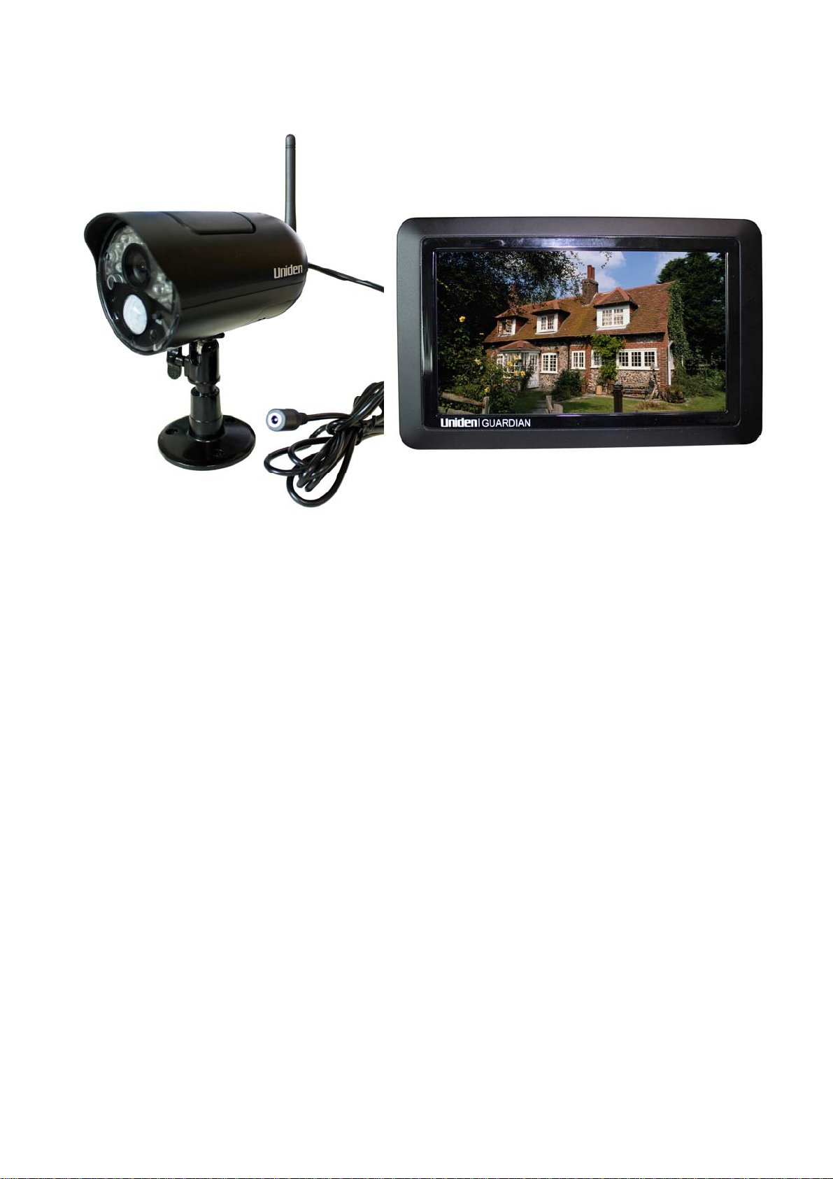
Guardian UDRC57 Accessory Camera
UDR777HD
Guardian UDR777HD Wireless System
Trade mark: Uniden
Applicant: RDI Technology (Shen zhen) Co., Ltd
Page 2

Feature list:
850nm IR Led visible distance up to 10m
7” TFT Lcd Digital panel (1080 RGB x 600)
Two way audio
Scan function
PIR trigger or Video motion detect recording
Manual recording
Touch button operation
Schedule recording separate settings from Monday to Sunday
SD Card external storage, up to128GB supported
One Lcd monitor can pair four cameras
Individual recording files
Pre-recording
Lcd : 5v DC 2A Power adaptor (+/-5%)
Camera: 9v DC 600mA (+/-5%)
RF range: 150 meter (Line of sight)
New recording indicator/ Memory card full indicator
Quad view
PIR trigger and Video motion detect alert
Touch panel
Remote view and playback from Android or iOS Smartphone
Page 3
Wireless Receiver
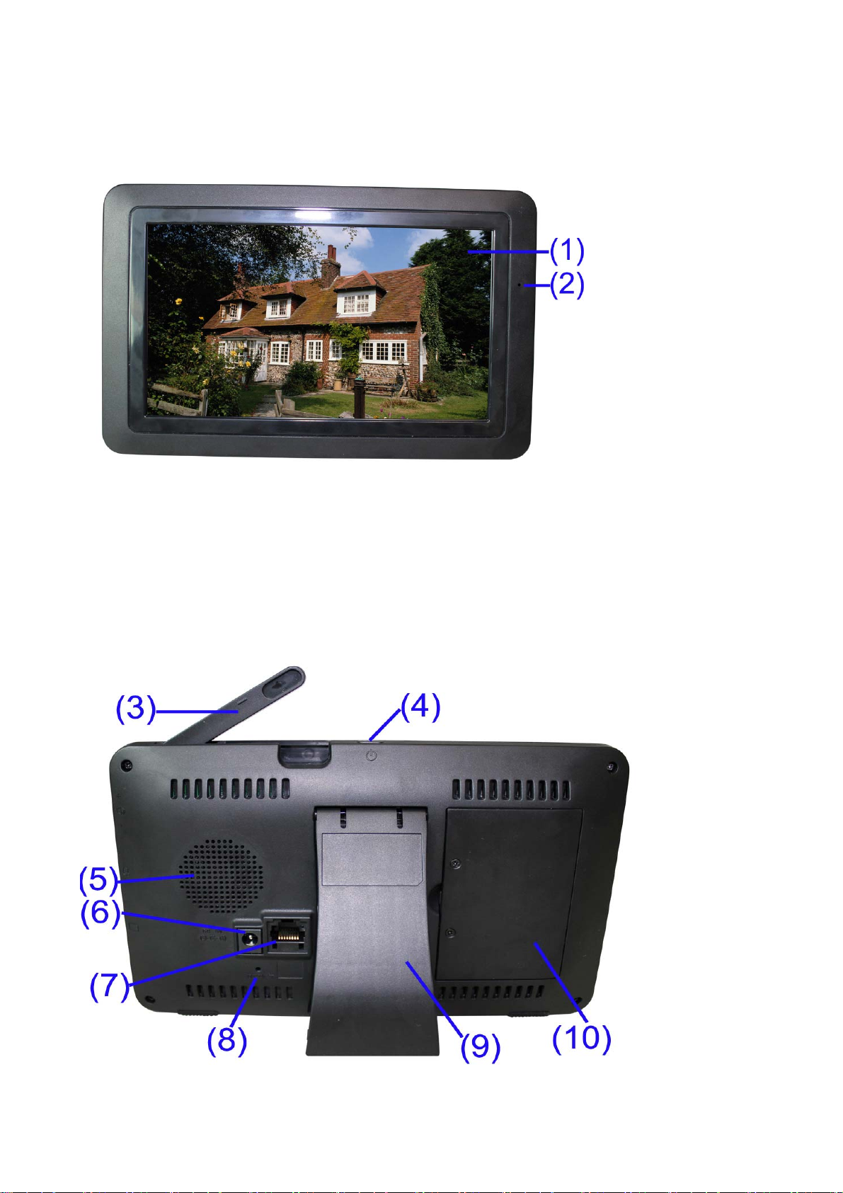
Front View
1. LCD Screen – Displays video from the camera(s) or displays system operations.
2. Microphone
Back controls
Page 4
3. Wireless Antennas: Position the antennas as needed for best reception.
4. Power Button/ Scan Button: Press and hold to turn the receiver on / off. Press and release while the
unit is powered on to turn Scan mode.
5. Speaker
6. Power Port: Connect to a local power outlet using the included power adapter.
7. Ethernet Port (RJ45): Connect the receiver to your router using the included Ethernet cable to
enable smartphone / tablet connectivity.
8. Reset: Using a paper clip or other thin object, push the reset button to restore the system to its
default settings.
9. Receiver Stand
10. Battery Cover
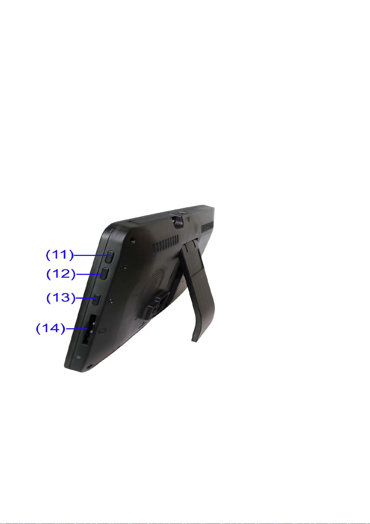
Side controls
11. Volume Up
12. Volume Down
13. Talk - Press and hold talk button in single channel view mode to talk back to camera side.
14. SD Card Slot- insert SD card for recording videos.
Page 5

Wireless Camera
Camera Antenna – Sends & receives signals to or from the receiver.
1.
2. IR LEDs – Infrared LEDs provide viewing in no/low light conditions
3. Camera Lens –Catches the video in front of the lens and transmits video from camera to receiver.
4. Light Sensor- sense brightness for changing between daytime vision and night vision.
5. Microphone- transmit audio to receiver
6. Pair Button – The pair button is located on the back of the camera, it is used to pair the camera with
receiver.
7. PIR Sensor – Detects motion in front of the lens and emits detection signal to transmitter.
8. Wall Mounting Bracket – Use the bracket to mount the camera on a wall or other flat surfaces.
9. AC Adaptor Jack – Plug the AC adaptor to the jack for camera’s power supply.
10. Speaker – Produces the sound transmitted from the receiver.
Note:This camera includes an Auto Mechanical IR Cut Filter. When the camera changes between day
mode and night vision mode, an audible clicking noise may be heard coming from the camera. This
clicking is normal, and indicates that the camera filter is working.
Page 6

Camera Installation
Before you install the camera, carefully plan where and how it will be positioned, and where you will
route the cable that connects the camera to the power adaptor.
Before starting permanent installation, verify its performance by observing the image on the receiver
when camera is positioned in the same location/position where it will be permanently installed and the
receiver is placed in the location where it will be used most of the time.
Installation Warnings
Aim the camera(s) to best optimize the viewing area: Select a location for the camera that provides a
clear view of the area you want to monitor, which is free from dust, and is not in line-of-sight to a strong
light source or direct sunlight.
Avoid installing the cameras where there are thick walls, or obstructions between the Cameras and the
Receiver.
Night Vision
This camera has built-in IR LEDs, which provides the camera with the ability to view images in no/low
light conditions.
Installing the Camera
1. Carefully unpack the camera.
NOTE: If you are installing cameras that did not come with the system,
please see the pairing camera section of this manual for details on
installation.
2. Mount the camera to the wall.
Mark the position of the screw holes on the wall, and drill holes and insert
3 screws, then firmly attach the camera to the wall. Make sure to strongly
secure the screw the mounting bracket into the wall
NOTE: The camera can also be placed on a flat surface, such as a Table
or Shelf, and no mounting hardware is required.
3. Adjust the viewing angle of the camera. You can adjust camera angle
to desired viewing area.
NOTE: You can install additional cameras (maximum of 4 cameras).
When adding cameras that were not included in the original box, you will need to pair up the cameras
with the receiver. Refer to the camera pairing section of this manual.
Connecting Camera Power
The camera can be powered by using the provided power adaptor
Power Adaptor
Connect the power adaptor to the camera.
Make sure is the DC 9V for camera, and DC 5V for Receiver
Make sure the power adaptor is placed into a grounded outlet or surge bar to
protect the camera from power fluctuations.
Page 7
1 Using the system
By default, the camera(s) included with your system are automatically paired to the receiver.The
camera(s) and receiver will communicate with each other once they are powered on.
Note:It is recommended to power on the cameras before powering on the receiver.
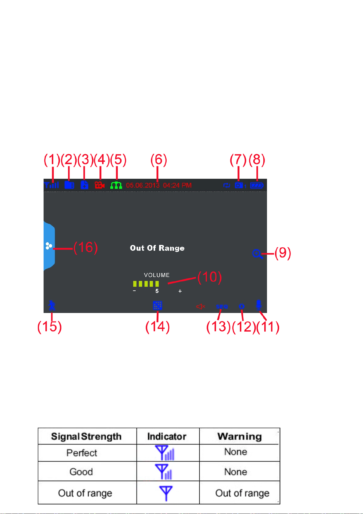
1.1 Understanding the On-screen Display
With camera 1 properly connected and powered on, the system displays a full-screen live view of the
camera.
1. Signal Indicator –The signal indicator shows the strength of the signal being received from the
camera. The number of bars in the Signal Indicator shows the strength of the signal. One, or no bars
indicates the signal is poor, and 4 bars indicate a very strong signal.
Note:
• If the signal is low (e.g.,1 or 2 bars) adjust the antennas, or reposition the cameras or receiver for
best performance.
• The signal indicator is not shown during Quad mode.
Signal Indicators:
Page 8
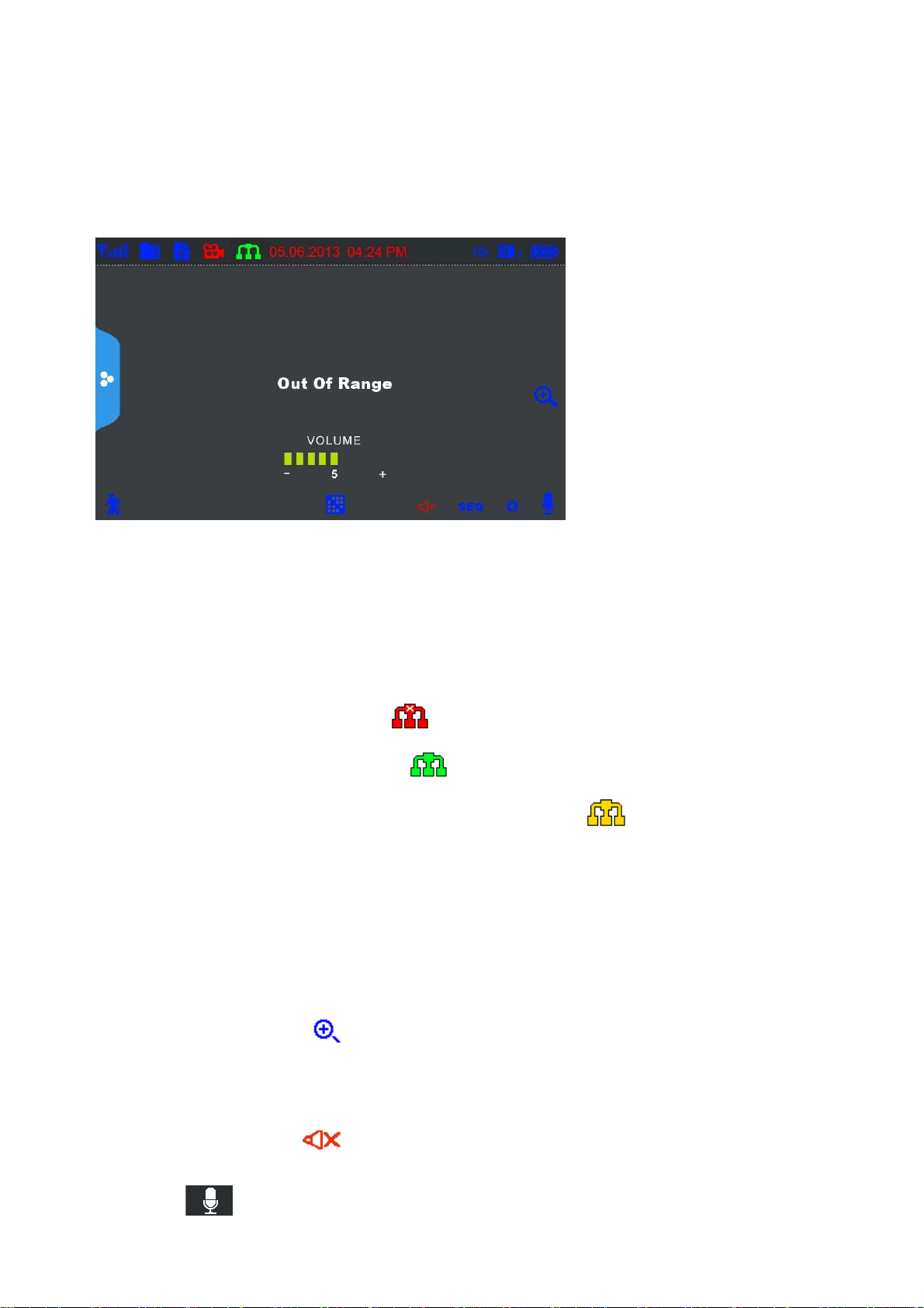
OOUT OF RANGE Warning
When the receiver can’t get signal from cameras, warning message will be displayed. Reposition the
camera, or check the camera power connection.
2. SD Card Indicator – When a SD card is inserted into the SD card slot, the indicator will be shown on
the LCD screen. A blue icon shows that a SD card with available recording space is inserted in the
receiver. A red icon indicates the SD card is full.
3. New Record Indicator- Indicates that there are new recordings saved to the microSD card.
4. Recording Indicator–When this icon flash in red and blue, it says that the system is recording vedio
into the SD card.
5. Network status Indicator –A red icon
not connected to a network. A green icon
and tell you the monitor connect with internet mode. A yellow icon
connected to the intranet and tell you the monitor connect with intranet mode.
6. Time stamp-The current date and time on the system(month/date/year, hour/minute/second)
7. Channel Indicator–Displays the current channel number you are presently viewing. If viewing
multiple cameras at once, the camera indicator will appear above each video display.
8. Battery Indicator-Indicates the battery life of LCD monitor in low battery will show red and the green
LED under the indicator light will flash.
9. Zoom Indicator-Press the
you want to see in Zoom, the screen will show that area in x2 size. Press the icon again to exit zoom
mode.
10. Volume indicator-Shows the current volume of the receiver. You must be in single channel viewing
mode to change volume,
11. Talk back Indicator- Press and hold Talk Button on the monitor then talk back to the camera, the
icon on the screen, the monitor will show in 5 areas, press the area
indicate that the volume is 0.
shows that the connection has failed or the system is
shows that the system is connected to the Internet
shows that the system is
indicator
will be shown on the LCD screen.
Page 9
12. New download icon- appears on the screen if new firmware is available.
13. Sequence view indicator: when “SEQ” shows on the screen, it means the monitor is auto switch
mode. The monitor will change channel automatically.
14. Change Channel- Press this icon to change channel manually. When you have manually view all
the channels, press this icon again, the monitor will enter auto switch mode, the “SEQ” icon will
shows on the screen. Press again to exit auto switch mode, the “SEQ” icon will disappear.
Note: If you want to enter Quad mode, just press the central part of the screen. The screen will
split into quad or half quad mode. And choose the channel you want to view and press, the
monitor will be back to single channel view.
15. Motion recording indicator- Indicates that motion recording is turned on
16. Menu- Press this icon to access menu system.
2 Viewing Modes
There are four different viewing modes available on the system: single channel viewing, Auto Sequence
Viewing mode (view individual channels automatically in sequence), Quad
Note: Auto Sequence Viewing mode cycles through connected channels in full-screen.
Use Quad mode to view up to four cameras simultaneously.
Use Scan mode, the receiver’s LCD screen and speaker will turn off unless motion is detected by one of
the cameras. The LCD screen turns on and displays video from the camera where motion was detected
for 15 seconds before turning off again. This conserves battery power and alerts you only when needed.
You can configure how much motion is needed to turn the display on in Scan mode by changing a
camera’s video motion detection settings. When exiting Scan mode, the receiver resumes live viewing in
Auto Sequence Viewing mode.
mode, and Scan mode.
To change viewing modes:
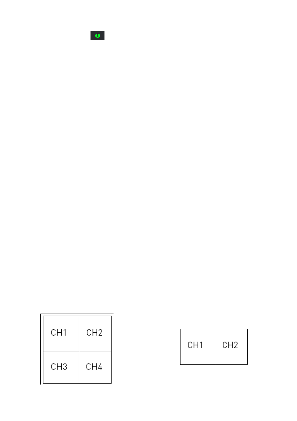
Press cental part of the screen to enter Quad mode (half-Quad mode when only 2 cameras are
connected). OR Press change channel icon to switch between channels 1~4 in single channel view.
Page 10

Quad mode half- Quad mode
Note: When you only pair a camera or set one camera on(other three is off), there is no access to see
QUAD mode.
3 SD Card Recording
The system records video to the SD card (not included). You can manually record the video at your
desire or the receiver records when there is motion detected by the cameras and under the A/REC
function, or schedule recording based on the scheduled you set for each camera. Before recording, you
need to insert a SD card to the SD card slot. The system can support up to 128GB SD card.
Recording Prerequisites: A SD card must be inserted into the receiver in order to record video. You
should always format the SD card prior to initial recording.
The following recording modes are available on the system: manual recording, schedule recording, and
motion recording. Record up to 4 channels at the same time.
3.1 Motion Recording
System only records when motion is detected by a camera(s).Press
receiver to start motion recording. There is a
starts recording prior to 5 seconds when motion detected by any activated camera. The recording time
can be set to 15s,30s or 1minitus after last detection. (Receiver support recording 4 camera at the same
time in quad mode)
3.2 Manual Recording
,Press Record on the up-left part of the receiver to starts manual recording. Press the icon again to stop
manual recording.
Note: In Quad view,it can continuous record from up to 4 cameras at a time.
3.3 Schedule Recording
Continuous or motion event recording from up to four cameras according to a weekly schedule. Set the
recording start time and end time, then switch on schedule recording in the menu to enable schedule
recording. In this mode the receiver records at a certain time every day.
3.4 Overwrite
Enter recording menu—overwrite—choose “yes” to activate overwrite function. Overwrite function can
automatically delete previous records when the SD card is full, and record new films.
on the bottom left corner. In this mode the receiver
Motion on the front panel of the
4 Playback
Playback mode allows you to playback recorded video files from the micro SD card. You can view videos
Page 11

or images directly on the system or by connecting the micro SD card to your computer.
4.1 Video Playback
To playback recorded video on the system:
1. During live viewing, push joystick, The
Recording File List opens.
2. Move the Joystick up / down to change
the displayed month.
3. Select the channels you would like to
view recordings from:
• Move the joystick left / right arrow to
select the channel numbers
•Move the joystick up / down arrow to show
or hide each channel on the calendar.
• Select the button with all four channels to
show recordings from all connected cameras
on the calendar.
4. Once you have selected the month and
the channels to display on the calendar,
push the joystick to refresh the display.
Dates that have recordings available for
playback are highlighted in green.
5. Move the joystick left / right to select a
date on the calendar, and push the joystick
to view a list of recordings for that date.
Note:
• The system uses a 24-hour clock.
• Recordings are named by start time in hhmmss format and the channel number (for example, the
recording 133245-2 began recording at 1:32:45 PM on channel 2).
6. Select a file from the list and push the joystick to confirm then the selected file loads and playback
begins.. Move the joystick left / right to change pages to find video files quickly. The selected file loads
and playback begins.
4.2 Playback controls:
1. Playback duration: Shows the length of
the recording and how much has been
viewed.
2. File name
3. Playback status: Shows whether the
video is playing, paused, or stopped.
To control playback using the joystick:
•LEFT: Rewind (2x > 4x > 8x > 16x).
•UP: Pause / Play video.
•RIGHT: Fast-forward (1x>2x > 4x > 8x >
Page 12

16x).
•DOWN: Stop video.
• To change playback volume, press Volume Controls on the side of the receiver.
To exit playback: Press Menu to return to the file list. Press Menu repeatedly to return to live
view.
4.3 Deleting Video Files
You can delete files on the SD card directly on the
system. Delete files if you need to clear space on the
SD card (if file overwrite is disabled), or for your own
file management purposes.
To delete files on the SD card, you can either delete
from the play file list on delete when viewing the
playback video. Press the delete icon and confirm
“YES” to delete selected video file.
CAUTION:Do NOT delete folders on the SD card using your computer. Deleting folders may affect your
access to other files on the card or may affect normal operation of the SD card with the system. If you
want to delete the entire contents of the SD card, it is highly recommended to format the card using the
system.
Viewing Video Directly from the SD Card
You can view the saved video files on your computer (PC or Mac) by using a SD card reader (not
included). Saved video files are in ASF format.
Note:
1. Some PCs and Macs may have a SD card reader built-in. Please refer to your computer's instruction
manual for more details.
2. You can view ASF files natively in Windows Media Player, as well as other media players such as
VLC.
VLC is an open-source software application available at www.videolan.org
To playback recorded video on a PC:
1. Remove the SD card from the receiver by gently pushing on the SD card and then releasing. The card
will eject.
2. Insert the SD card into a SD card reader (not included) connected to your PC. Your PC should load
the SD card as a new Removable Drive and an Auto run window opens.
3. Click Open folder to view files or open the folder in Computer. Open the folder MFG.
Y ou will then see a folder for each pa ge of recorded video in Playback mode. Folders are named by page
number (e.g. recordings found on the second page are in the folder 00000002).
4. Double-click any of the ASF files. The video will begin playing in your default ASF media player.
5 Accessing Menu System
Page 13

Touch Menu icon on the receiver to access to Menu system.
The Main Menu contains 4 submenus: Playback, Alarm, Brightness, General Settings
1. Playback –Use the menu for viewing recorded videos on the SD card.
2. Alarm– Adjust receiver beeps volume level when motion detected by
camera.
Page 14

3. Brightness- Adjust screen brightness.
4. General Settings- 6 sub-menus under “General Settings” (see
below picture)
5.4.1 Camera Setup
Page 15

a. Pairing
The system comes with camera(s) that have already been paired. These cameras will communicate
with the receiver once powered on.
The pairing function assigns each camera to a different channel on the wireless receiver (up to 4
cameras), and is necessary for configuring additional cameras.
NOTE: It is highly recommended to pair the cameras to the receiver before permanently mounting
the cameras.
Paring steps:
1. Power on the camera by connecting it to power outlet with supplied 9V power adaptor.
2. Power on the receiver by connecting it to power outlet with supplied 5V power adaptor.
3. Press “Pairing” in the Camera Setup menu. Choose the channel you want to pair the camera with.
(If you pair a new camera to a channel that is already being used by an existing camera, the new
camera will be connected to that channel. The old camera will automatically be disconnected.
4. A message will be displayed on the receiver screen “PLEASE PRESS
PAIR KEY ON CAMERA SIDE XX”. The receiver will count down from 30~0
– you must press the Pair button on the camera during this time to
Page 16

successfully pair the camera. If the button on the camera is not pressed, the receiver will return to
the view screen, and no pairing will take place.
5. Following the on-screen prompt, press the Pair button the front of the
camera. You have 30 seconds to press the Pair button on the camera, once
paired, after 3s will see the live video on monitor
b. Camera ON/ OFF
Turn on/ off the camera by touching the switch bar below the camera icon. When turning on/ off the
camera, the screen will show “Please wait…”. When the camera is on, the left part of the switch bar
is in GREEN color, while if the camera is off, it will be in GREY color.
c. Resolution
Select the frame rate for each camera by High and Low
5.4.2 Recording Setup
Page 17

a. Duration
The recording time when there is motion detected by a camera in automatic recording mode. The
recording time can be set to 15s ,30s or 1 minute.(Default 15s)- Date & Time: Set the date and time on
the system.
b. Schedule Recording
Use scheduled recording to have the system automatically record continuously or based on motion from
one or more cameras according to a selected start and stop time. Scheduled continuous recording will
record constantly, whereas scheduled motion recording will only record scenes of movement within the
scheduled recording time.
Set a recording schedule:
1. Enter Schedule recording sub-menu, press “Modify” on the bottom right.
2. Edit the start time and end time of your recording schedule. You can choose different schedule for
different camera.
3. Select “ Save” or “Delete” when finishing editing.
Page 18

Stopping Scheduled Recording
When the stop time arrives, the system stops recording automatically. If necessary, you can stop
schedule recording manually.
To stop schedule recording: Press Manual Recording to stop schedule recording.
c. File Overwrite
Use the overwrite feature to have the system overwrite the oldest recorded data on the mirco SD card
once the SD card is full.
Page 19

5.4.3 System Setups
a. Date & Time
Set up date and time manually.
Note:You can also synchronize the system time with an Internet time server. Ensure there is a
checkmark next to Synchronize with an Internet time server then push the joystick to confirm.
Y ou must keep the system connected to y our wireless network using the included Ethernet cable
to synchronize with the Internet time server.
b. Time Zone
Select the time zone where the system is being used and enable / disable Daylight Savings Time (DST).
Page 20

c. Language
There are 3 languages available in this system: English, Spanish and French
d. Default Settings
Restore the system to default settings(Default No).
Select Yes and then press OK to confirm. The system takes a few moments to restore default settings.
Page 21

e. Format Memor y Card
Select Yes to format the SD card. After formatting, all the data stored in the SD card will be
deleted.
(default NO)
f. Information
It shows the firmware information of the monitor and cameras which paired with the monitor.
5.4.4 Motion Detection Settings
Separately to Set each Camera’s motion detect sensitivity and Detect Area
Page 22

a. Sensitivity
Set the motion detection sensitivity at High or Low. Or you can turn off the motion detection for the
camera
b. Mask Area
Default setting is 80% of the screen count from central part.
Page 23

5.4.5 Network Setup
a. Advanced Setup
Set up Dynamic IP or Static IP address
Page 24

b. Reset Password
Password will be changed to default password when confirmed Yes.
c. Network Information
when connect to Internet, it will show the current IP information.
when you successfully set up the Network settings, system will remind if you want to reboot the
monitor
Page 25

5.4.6 Firmware Upgrade
There are two ways to upgrading firmware: from SD card and from Server
a. From SD Card
1. Insert the SD card into the SD card reader (not included) on your PC or Mac.
2. Download the latest firmware and transfer it to the root folder on the SD card.
3. Once the transfer is complete, insert the SD card into the card slot on the receiver.
4. Select Firmware Upgrade and choose From SD Card. The system takes a few moments to install
the latest firmware.
5. The system takes a few moments to install the latest firmware.
b. From Server
Page 26

1. Connect the included Ethernet cable from the Ethernet port on the receiver to your router. The new
download icon (
2. Select Firmware Upgrade and select From Server, then select Yes.
3. The system takes a few moments to install the latest firmware.
4. After upgrading the new firmware, the monitor will automatically reboot .
) appears on the screen if new firmware is available.
Page 27

Android and iOS App Remote view
1. Download app MyCam View freely from the App Store or the Google player store on
your smart phone or tablet.(Make sure your phone connect with network)
2. Connect the 7’’monitor with your home router by internet cable.
3. Add camera(Android APP for example)
Touch the App icon MyCam View to launch the app, Tap “Click here to add camera”
Then the right pictures as showed, there are 2 options to get the UID from the monitor.
Option A: Enter the UID printed below the
QRcode(example:D7ETGG7YPUUZUNPYWM4J) as it shows on the back of monitor.
Option B: Tap Scan button to scan the QRcode on the back of monitor.
Name: Press it to rename the camera(original name is MyCam View)what you want.
Enter the Password:000000(Default setting)
Page 28

Then press OK to confirm it.
4. The system will show in your device list at an online status as below picture.
5. Press the camera you have added on your device, now you can view live video from
your camera in either portrait or landscape mode.
Page 29

View icon : press this icon to view Snapshot photos already taken.
Snapshot Icon
Mute Icon
: press this icon to take photo from camera side
: It cut off the audio on the camera side.
Press this icon to listen the audio from camera side.
Talk back Icon :Press it to talk back to the camera currently being displayed on your
phone.
CH Icon : press this icon to change channel which you want to see.
Page 30

Online:1,only one remote visit, system support 4 remote visit at the same time.
Quality: shows the network quality.
6. Back to the add camera menu, then press the down arrow, a new interface pops out as
showed .
Page 31

Reconnect: If your remote device connected failed with the camera, press it to reconnect.
Edit Device: Device setting and Advanced setting are
under this menu. You can see the camera’s details
under Device Setting.
You can modify Password setting(default 000000) ,
video Quality(default Min) and Alert interval(default 3
MIN)under Advance setting.
View Event: Select it to playback the video on your phone. You can tap
icon to
view live video by selecting a period of time(within an hour, within half a day, within a day,
and within a week) or as you want by Custom time.
View Snapshot: Select it to view the photos you have taken by Snapshot key.
Remove Device: Delete this camera from your phone
Page 32

Caution:
Note : Cet appareil est conforme à la Partie 15 des règlements de la FCC et aux normes
RSS de l’Industrie du Canada. Son fonctionnement est soumis aux deux conditions
suivantes : (1) cet appareil ne doit pas causer des interférences nuisibles, et (2) cet
appareil doit accepter toute interférence reçue, y compris les interférences qui peuvent
provoquer un fonctionnement indésirable.
Le fabricant n'est pas responsable des toutes interférences radio ou télévision causées par
des modifications non autorisées apportées à cet appareil. De telles modifications peuvent
empêcher l’utilisateur d’utiliser l'appareil.
Le présent émetteur radio (identifier le dispositif par son numéro de certification ou son
numéro de modèle s'il fait partie du matériel de catégorie II) a été approuvé par Industrie
Canada pour fonctionner avec les types d'antenne énumérés ci‑dessous et ayant un gain
admissible maximal. Les types d'antenne non inclus dans cette liste, et dont le gain est
supérieur au gain maximal indiqué, sont strictement interdits pour l'exploitation de
l'émetteur.
Antenna Type Max. Antenna Gain(dBi)
Dipole 2
This device complies with Part 15 of the FCC rules and Industry Canada license-exempt
RSS standard(s). Operation is subject to the following two conditions: (1) this device may
not cause harmful interference, and (2) this device must accept any interference received,
including interference that may cause undesired operation.
The manufacturer is not responsible for any radio or TV interference caused by
unauthorized modifications or change to this equipment. Such modifications or change
could void the user’s authority to operate the equipment.
This radio transmitter (identify the device by certification number or model number if
Category II) has been approved by Industry Canada to operate with the antenna types
listed below with the maximum permissible gain indicated. Antenna types not included in
Page 33

this list, having a gain greater than the maximum gain indicated for that type, are strictly
prohibited for use with this device.
This equipment has been tested and found to comply with the limits for a Class B digital
device, pursuant to part 15 of the FCC Rules. These limits are designed to provide
reasonable protection against harmful interference in a residential installation. This
equipment generates, uses and can radiate radio frequency energy and, if not installed and
used in accordance with the instructions, may cause harmful interference to radio
communications. However, there is no guarantee that interference will not occur in a
particular installation. If this equipment does cause harmful interference to radio or
television reception, which can be determined by turning the equipment off and on, the user
is encouraged to try to correct the interference by one or more of the following measures:
-- Reorient or relocate the receiving antenna.
-- Increase the separation between the equipment and receiver.
-- Connect the equipment into an outlet on a circuit different from that to which the receiver
is connected.
-- Consult the dealer or an experienced radio/TV technician for help.
The device has been evaluated to meet general RF exposure requirement.
To maintain compliance with FCC’s RF exposur
portable devise, and should be installed and operated with a minimum distance of
20cm between the radiator and your body.
e guidelines, this equipment is not a
 Loading...