

Page 1

WIRELESS SECURITY CAMERA
INSTRUCTION MANUAL
ENGLISH VERSION 1.0
LW2231
www.lorextechnology.com
Page 2
Thank you for purchasing this product.
This manual refers to the following models:
• LW2231
To learn more about this product and to learn about our complete range of accessory
products, please visit our website at:
www.lorextechnology.com
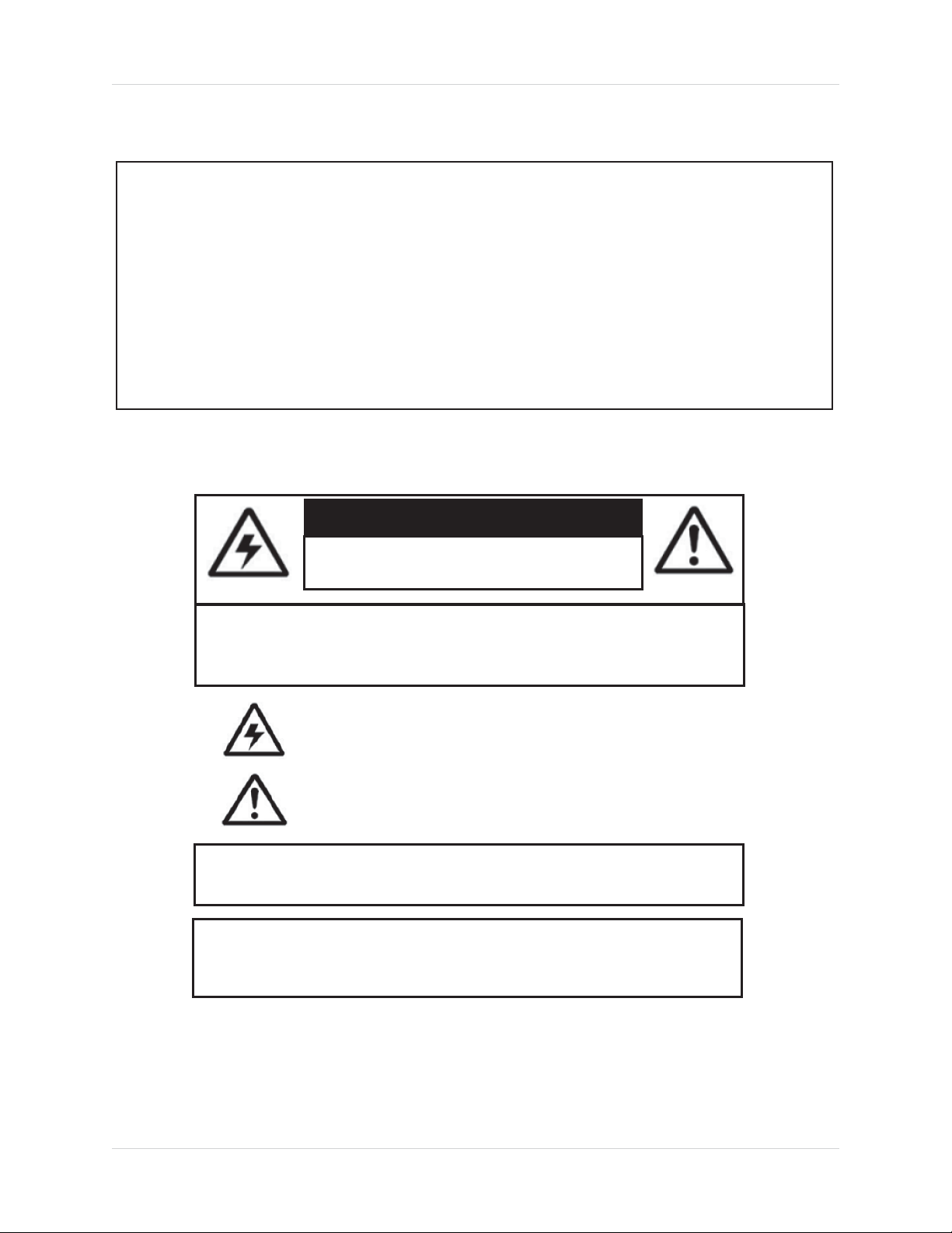
CAUTION
RISK OF ELECTRIC SHOCK
DO NOT OPEN
CAUTION: TO REDUCE THE RICK OF ELECTRIC SHOCK DO NOT
REMOVE COVER. NO USER SERVICABLE PARTS INSIDE.
REFER SERVICING TO QUALIFIED SERVICE PERSONNEL.
The lightning flash with arrowhead symbol, within an equilateral
triangle, is intended to alert the user to the presence of uninsulated
"dangerous voltage" within the products ' enclosure that may be of
sufficient magnitude to constitute a risk of electric shock.
The exclamation point within an equilateral triangle is intended to
alert the user to the presence of important operating and
maintenance (servicing) instructions in the literature accompanying
the appliance.
WARNING: TO PREVENT FIRE OR SHOCK HAZARD, DO NOT
EXPOSE THIS UNIT TO RAIN OR MOISTURE.
CAUTION: TO PREVENT ELECTRIC SHOCK, MATCH WIDE BLADE
OF THE PLUG TO THE WIDE SLOT AND FULLY INSERT.
Page 3

NEED HELP?
CONTACT US FIRST
DO NOT RETURN THIS PRODUCT TO THE STORE
Please make sure to register your product at www.lorextechnology.com
to receive product updates and technical support.
2 Easy Ways to Contact Us
Online:
Product Support is available 24/7 including product information, user
manuals, quick start up guides and FAQ’s at
www.lorextechnology.com/support
For all other matters, visit www.lorextechnology.com
By Phone:
North America:
Customer Service (for warranty matters): 1-888-425-6739 (1-888-42-LOREX)
Tech Support (for technical/installation issues): 1-877-755-6739 (1-877-75-LOREX)
Mexico: 001-800-681-9263, 001-800-514-6739
FEB 12 2013 - R15
International: +800-425-6739-0
(Example: From the UK, dial 00 instead of +)
Page 4

VIEW YOUR WORLD™
VOIR VOTRE MONDE
VEA SU MUNDO™
MD
¿NECESITA AYUDA?
COMUNÍQUESE PRIMERO
CON NOSOTROS
NO DEVUELVA ESTE PRODUCTO A LA TIENDA NE RETOURNEZ PAS CE PRODUIT AU MAGASIN
Por favor, registre su producto en www.lorextechnology.
com para recibir actualizaciones del producto y
asistencia técnica.
Hay 2 maneras fáciles de comunicarse
con nosotros:
En línea:
Apoyo al cliente está disponible 24/7, incluyendo
información del producto, manuales para el usuario, guías
de inicio rápido y preguntas más frecuentes en:
www.lorextechnology.com/support
BESOIN D’ASSISTANCE?
COMMUNIQUEZ D’ABORD
AVEC NOUS
Veuillez enregistrer votre produit sur le site
www.lorextechnology.com afin de recevoir des mises à jour
et le soutien technique pour votre produit.
2 façons simples de communiquer
avec nous :
En ligne :
À votre disposition 24/7, le soutien pour les produits comprend
les renseignements sur les produits, guides d’utilisation, guides
de départ rapide et FAQ :
www.lorextechnology.com/support
Para todo lo demás, visite
www.lorextechnology.com
Por teléfono:
Norte América:
Atención al cliente (para asuntos de la garantía - garantía válida sólo
en E.U.A., vea la garantía ofrecida por el importador):
1-888-425-6739 (1-888-42-LOREX)
Asistencia técnica (para asuntos técnicos o de instalación):
1-877-755-6739 (1-877-75-LOREX)
Teléfono y Servicios Válidos Sólo en E.U.A.:
001-800-681-9263, 001-800-514-6739
Internacional: +800-425-6739-0
Pour toutes les autres questions,
visitez www.lorextechnology.com
Par téléphone :
En Amérique du Nord :
Service à la clientèle (pour tout ce qui concerne la garantie) :
1-888-425-6739 (1-888-42-LOREX)
Soutien technique (pour les questions d’ordre technique ou relatives à
l’installation) : 1-877-755-6739 (1-877-75-LOREX)
Mexique : 001-800-681-9263, 001-800-514-6739
International : +800-425-6739-0
(par exemple : à partir du Royaume-Uni, composez le 00 au lieu de +)
FEB 12 2013 - R15
Page 5

BEFORE YOU START
Please make sure to register your product at www.lorextechnology.com
to receive product updates and technical support
THIS PRODUCT MAY REQUIRE PROFESSIONAL INSTALLATION
LOREX IS COMMITTED TO FULFILLING YOUR SECURITY NEEDS
• We have developed user friendly products and documentation.
Please read the Quick Start Guide and User Manual before you
install this product.
• Consumer Guides and Video Tutorials are available on our web
site at www.lorextechnology.com/support
•
If you require further installation assistance, please visit
www.lorextechnology.com/installation or contact a
professional installer.
• Please note that once the components of this product have been
unsealed, you cannot return this product directly to the store
FEB 12 2013 - R9
without the original packaging.
Page 6

AVANT DE
ANTES DE
COMMENCER
Veuillez enregistrer votre produit sur le site
www.lorextechnology.com afin de recevoir
des mises à jour et le soutien technique pour
votre produit.
CE PRODUIT PEUT NÉCESSITER UNE
INSTALLATION PROFESSIONNELLE
LOREX S’ENGAGE À RÉPONDRE À VOS
BESOINS EN MATIÈRE DE SÉCURITÉ
• Nous avons conçu et développé une documentation
et des produits extrêmement conviviaux. Veuillez
lire le Guide de départ rapide et le Guide
d’utilisation avant d’installer ce produit.
• Des guides pour consommateurs et des tutoriels
EMPEZAR
Cerciórese de por favor colocar su producto
en www.lorextechnology.com para recibir
actualizaciones y la información del producto
y soporte técnico.
ESTE PRODUCTO PUEDE EXIGIR UNA
INSTALACIÓN PROFESIONAL
LOREX SE COMPROMETE A SATISFACER
SUS NECESIDADES EN SEGURIDAD
• Favor de leer la guía de instalación rápida y la
guía del usuario antes de instalar este producto.
• Puede conseguir las guías del consumidor y los
cursos en enseñanza video sobre el Internet
visitando www.lorextechnology.com/support
vidéo vous sont offerts sur notre site Web :
www.lorextechnology.com/support
• Si vous avez besoin de plus d’assistance pour
l’installation de ce produit, veuillez visiter le site
www.lorextechnology/installation ou communiquez
avec un installateur professionnel.
• Veuillez prendre note que lorsque vous avez déballé
les pièces et composantes de ce produit, vous ne
pouvez pas retourner celui-ci directement au
magasin sans son emballage original.
www.lorextechnology.com
•
Si necesita ayuda para la instalación, visite
www.lorextechnology.com/installation o contacte
un especialista en instalaciones.
• Favor de notar que una vez que los componentes
de este producto han sido removidos del
embalaje, no podrá devolver este producto
directamente a la tienda.
VIEW YOUR WORLD™
VOIR VOTRE MONDE
VEA SU MUNDO™
MD
FEB 12 2013 - R9
Page 7
Important Safeguards
In addition to the careful attention devoted to quality standards in the manufacture process of
your product, safety is a major factor in the design of every instrument. However, safety is your
responsibility too. This sheet lists important information that will help to ensure your enjoyment
and proper use of the product and accessory equipment. Please read them carefully before
operating and using your product.
General Precautions
1. All warnings and instructions in this manual should be followed.
2. Do not use receivers or video monitors in humid or wet places.
3. Keep enough space around the product for ventilation. Slots and openings in the storage
cabinet should not be blocked.
4. It is highly recommended to connect the product to a surge protector to protect from damage
caused by electrical surges. It is also recommended to connect the product to an
uninterruptible power supply (UPS), which has an internal battery that will keep the product
running in the event of a power outage.
5. Remove the plug from the outlet before cleaning. Do not use liquid aerosol detergents. Use a
water dampened cloth for cleaning.
Installation
1. Read and Follow Instructions - All the safety and
operating instructions should be read before the product
is operated. Follow all operating instructions.
2.
Retain Instructions - The safety and operating
instructions should be retained for future reference.
3. Heed Warnings - Comply with all warnings on the
product and in the operating instructions.
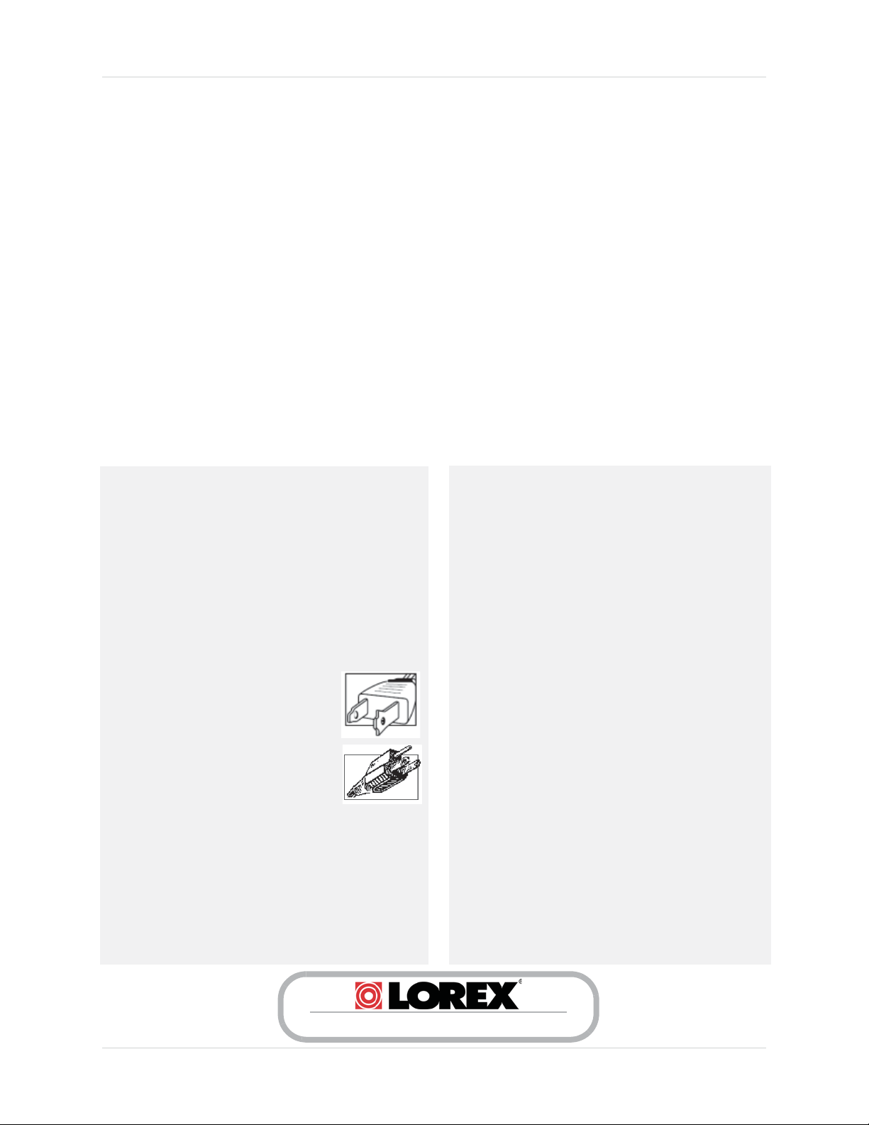
4. Polarization - Do not defeat the safety purpose of the
polarized or grounding-type plug.
A polarized plug has two blades with
one wider than the other.
A grounding type plug has two blades
and a third grounding prong.
The wide blade or the third prong are
provided for your safety.
If the provided plug does not fit into your
outlet, consult an electrician for
replacement of the obsolete outlet.
5.
Power Sources - This product should be operated only
from the type of power source indicated on the marking
label. If you are not sure of the type of power supplied
to your location, consult your video dealer or lo cal power
company. For products intended to operate from battery
power, or other sources, refer to the operating
instructions.
6. Overloading - Do not overload wall outlets or extension
cords as this can result in the risk of fire or electric
shock. Overloaded AC outlets, extension cords, frayed
power cords, damaged or cracked wire insulation, and
broken plugs are dangerous. They may result in a
shock or fire hazard. Periodically examine the cord,
and if its appearance indicates damage or deteriorated
insulation, have it replaced by your service technician.
7.
Power-Cord Protection - Power supply cords should
be routed so that they are not likely to be walked on or
pinched by items placed upon or against them. Pay
particular attention to cords at plugs, convenience
receptacles, and the point where they exit from the
product.
8.
Surge Protectors - It is highly recommended that the
video equipment be connected to a surge protector.
Doing so will protect the equipment from damage
caused by power surges. Surge protectors should bear
the UL listing mark or CSA certification mark.
9.
Uninterruptible Power Supplies (UPS) - Because
this product is designed for continuous, 24/7 operation,
it is recommended that you connect the product to an
uninterruptible power supply. An uninterruptible
power supply has an internal battery that will keep the
product running in the event of a power outage.
Uninterruptible power supplies should bear the UL
listing mark or CSA certification mark.
Caution: Maintain electrical safety. Power line
operated equipment or accessories connected to this
product should bear the UL listing mark or CSA
certification mark on the accessory itself and should
not be modified so as to defeat the safety features. This
will help avoid any potential hazard from electrical
shock or fire. If in doubt, contact qualified service
personnel.
www.lorextechnology.com
v
Page 8

Installation (Continued)
10. Ventilation - Slots and openings in the case are
provided for ventilation to ensure reliable operation
of the product and to protect it from overheating.
These openings must not be blocked or covered. The
openings should never be blocked by placing the video
equipment on a bed, sofa, rug, or other similar
surface. This product should never be placed near or
over a radiator or heat register. This product should
not be placed in a built-in installation such as a
bookcase or rack unless proper ventilation is provided
and the product manufacturer’s instructions have
been followed.
11.
Attachments - Do not use attachments unless
recommended by the product manufacturer as they
may cause a hazard.
12.
Water and Moisture - Do not use receivers or video
monitors near water — for example, near a bath tub,
wash bowl, kitchen sink or laundry tub, in a wet
basement, near a swimming pool and the like.
13.
Heat - The product should be situated away from
heat sources such as radiators, heat registers,
stoves, or other products (including amplifiers) that
produce heat.
14.
Accessories - Do not place this
video equipment on an unstable
cart, stand, tripod, or table. The
video equipment may fall,
causing serious damage to the
product. Use this product only
with a cart, stand, tripod,
bracket, or table recommended
by the manufacturer or sold with
the product. Any mounting of the product should
follow the manufacturer’s instructions and use a
mounting accessory recommended by the
manufacturer.
Camera Extension Cables – Check the rating of
15.
your extension cable(s) to verify compliance with your
local authority regulations prior to installation.
16.
Mounting - The cameras provided with this system
should be mounted only as instructed in this guide or
the instructions that came with your cameras, using
the provided mounting brackets.
17.
Camera Installation- Cameras are not intended
for submersion in water. Not all cameras can be
installed outdoors. Check your camera
environmental rating to confirm if they can be
installed outdoors. When installing cameras
outdoors, installation in a sheltered area is required.
Service
1. Servicing - Do not attempt to service this video
equipment yourself, as opening or removing covers
may expose you to dangerous voltage or other
hazards. Refer all servicing to qualified service
personnel.
2.
Conditions Requiring Service - Unplug this
product from the wall outlet and refer servicing to
qualified service personnel under the following
conditions:
A. When the power supply cord or plug is damaged.
B. If liquid has been spilled or objects have fallen into
the product.
C. If the product has been exposed to rain or water.
D. If the product has been dropped or the cabinet has
been damaged.
E. If the product does not operate normally by
following the operating instructions. Adjust only
those controls that are covered by the operating
instructions. Improper adjustment of other controls
may result in damag e and w ill ofte n requi re extensi ve
work by a qualified technician to restore the product
to its normal operation.
F. When the product exhibits a distinct change in
performance. This indicates a need for service.
7.
Replacement Parts - When replacement parts are
required, have the service technician verify that the
replacements used have the same safety
characteristics as the original parts. Use of
replacements specified by the product manufacturer
can prevent fire, electric shock, or other hazards.
Safety Check - Upon completion of any service or
8.
repairs to this product, ask the service technician to
perform safety checks recommended by the
manufacturer to determine that the product is in safe
operating condition.
Use
1. Cleaning - Unplug the product from the wall outlet
before cleaning. Do not use liquid cleaners or aerosol
cleaners. Use a damp cloth for cleaning.
2.
Product and Cart Combination - Product and cart
combination should be moved with care. Quick stops,
excessive force, and uneven surfaces may cause the
product and cart combination to overturn.
3.
Object and Liquid Entry - Never push objects of any
kind into this product through openings as they may
touch dangerous voltage points or “short-out” parts
th at co ul d r es ul t in a f ir e o r e le ct ri c s ho ck . N ev er sp il l
liquid of any kind on the product.
4. Lightning - For added protection of this product
during a lightning storm, or when it is left unattended
and unused for long periods of time, unplug it from
the wall outlet and disconnect the antenna or cable
system. This will prevent damage to the product due
to lightning and power line surges.
vi
Page 9

Features
• Real-time (up to 30fps) wireless video with MPEG-4 compression @ 640x480 (VGA) resolution
• Extended bandwidth delivers super smooth high frame rate video
1
• SignalGuard Technology continuously monitors the wireless signal and automatically
reconnects upon detecting low signal strength
• Next generation adaptive Frequency Hopping Spread Spectrum (FHSS) technology greatly
reduces conflicts with competing signals
• Built-in microphone for listen-in audio
2
• Built-in auto-mechanical infrared camera filter achieves accurate color reproduction in
varying lighting conditions
• Night vision range up to 135ft (41m) / 90ft (27m)
• Simple installation. No video cable required
• Weatherproof camera and power connectors, can be installed indoors or outdoors
3
4
5
• Easily connects to any surveillance DVR (BNC) or TV (RCA)
• High gain antennas provide up to 165ft (50m) indoor / 500ft (152m) outdoor wireless range
• Vandal resistant camera design with cable pass-through mounting bracket
1
6
1. At full signal strength. Limit number of obstructions to ensure best performance.
2. Audio recording without consent is illegal in certain jurisdictions. Lorex Technology Inc. assumes no liability for use of its
products that does not confirm with local laws.
3. Stated IR illumination ranges are based on ideal conditions in typical outdoor night time ambient lighting and total darkness.
Actual range and image clarity depends on installation location, viewing area and light reflection/absorption level of object.
4. Camera and receiver requires a wired connection to an electrical outlet (power adapters included).
5. Not intended for submersion in water. Installation in a sheltered area required.
6. Maximum wireless transmission range. Actual range dependent upon building materials and other obstructions in path of
wireless signal.
viii
Page 10

Table of Contents
1. Getting Started . . . . . . . . . . . . . . . . . . . . . . . . . . . . . . . . . 1
2. Wireless Receiver. . . . . . . . . . . . . . . . . . . . . . . . . . . . . . . 2
3. Wireless Camera . . . . . . . . . . . . . . . . . . . . . . . . . . . . . . . 3
4. Installing the Camera. . . . . . . . . . . . . . . . . . . . . . . . . . . . 4
4.1 Installation Warnings . . . . . . . . . . . . . . . . . . . . . . . . . . . . . . . . . . . . . . . . . . . . . . . . . . 4
4.2 Mounting Positions . . . . . . . . . . . . . . . . . . . . . . . . . . . . . . . . . . . . . . . . . . . . . . . . . . . . 5
4.3 To Install the Camera . . . . . . . . . . . . . . . . . . . . . . . . . . . . . . . . . . . . . . . . . . . . . . . . . . 5
5. Connecting to a DVR . . . . . . . . . . . . . . . . . . . . . . . . . . . . . 7
6. Connecting to a TV . . . . . . . . . . . . . . . . . . . . . . . . . . . . . . 8
7. Pairing Cameras . . . . . . . . . . . . . . . . . . . . . . . . . . . . . . . . 9
8. Appendix A: System Specifications. . . . . . . . . . . . . . . . 10
8.1 General Specifications . . . . . . . . . . . . . . . . . . . . . . . . . . . . . . . . . . . . . . . . . . . . . . . .10
8.2 Receiver Specifications . . . . . . . . . . . . . . . . . . . . . . . . . . . . . . . . . . . . . . . . . . . . . . . 10
8.3 Camera Specifications . . . . . . . . . . . . . . . . . . . . . . . . . . . . . . . . . . . . . . . . . . . . . . . . 10
9. Appendix B: Frequently Asked Questions . . . . . . . . . . 11
9.1 Wired vs. Wireless Cameras . . . . . . . . . . . . . . . . . . . . . . . . . . . . . . . . . . . . . . . . . . . 11
9.2 Does a wireless camera require power? . . . . . . . . . . . . . . . . . . . . . . . . . . . . . . . . . 11
9.3 How far can a wireless camera transmit a video signal? . . . . . . . . . . . . . . . . . . . . 11
9.4 Are digital wireless camera signals secure? . . . . . . . . . . . . . . . . . . . . . . . . . . . . . . 12
9.5 How many frames per second should I expect from a digital wireless camera? . 12
9.6 How many wireless cameras can I install? . . . . . . . . . . . . . . . . . . . . . . . . . . . . . . . 12
10. Appendix C: Troubleshooting . . . . . . . . . . . . . . . . . . . 13
11. Appendix D: Extending Wireless Signal Range. . . . . 14
ix
Page 11

x
Page 12

1. Getting Started
1 X MOUNTING KIT
1 X WIRELESS CAMERA 1 X WIRELESS RECEIVER 2 X POWER ADAPTERS
(FOR CAMERA & RECEIVER)
1 X BLACK RECEIVER ANTENNA
(PRE-ATTACHED)
The system comes with the following components:
Getting Started
1 X WHITE CAMERA ANTENNA
(Mounting kit contents may differ
from image)
(PRE-ATTACHED)
INSTRUCTION MANUAL
ENGLISH VERSION 1.0
WIRELESS SECURITY CAMERA
LW2231
www.lorextechnology.com
1 X BNC-TO-RCA ADAPTER
2 X DOUBLE-SIDED TAPE
1 X INSTRUCTION MANUAL
1 X QUICK START GUIDE
11
CHECK YOUR PACKAGE TO CONFIRM THAT YOU HAVE RECEIVED THE COMPLETE SYSTEM,
INCLUDING ALL COMPONENTS SHOWN ABOVE.
1
Page 13

Wireless Receiver
2. Wireless Receiver
1
2
3
1 Removable Antenna (SMA Type): Pre-attached to the receiver.
2 Pa
3 Pa
4 DC Power: Connect power adapter
5 Te
6 Ant
iring Status LED: Glows green continuously when a camera is paired to the receiver.
Flashes on and off slowly when pairing mode is active and flashes rapidly when camera is out
of range.
iring Button: For details, see
“Pairing Cameras” on page 9.
to power on the receiver.
rmination Cable: Includes BNC
video output cable and RCA audio
output.
enna Jack
RCA Audio
BNC Video
4
5
6
2
Page 14

3. Wireless Camera
Wireless Camera
2 3
1
4
5 6
1 Microphone
2 Remo
3 Camera Stand
4 DC
5 Pairing Button: For details, see “Pairing Cameras” on page 9.
6 Antenna Jack
vable Antenna (SMA Type): Pre-attached to the back of camera.
Power: Connect power adapter to power on the camera.
ATTENTION - This camera includes an Auto Mechanical IR Cut Filter. When the camera
changes between Day/Night viewing modes, an audible clicking noise may be heard
from the camera. This clicking is normal and indicates that the camera filter is working.
3
Page 15
Installing the Camera
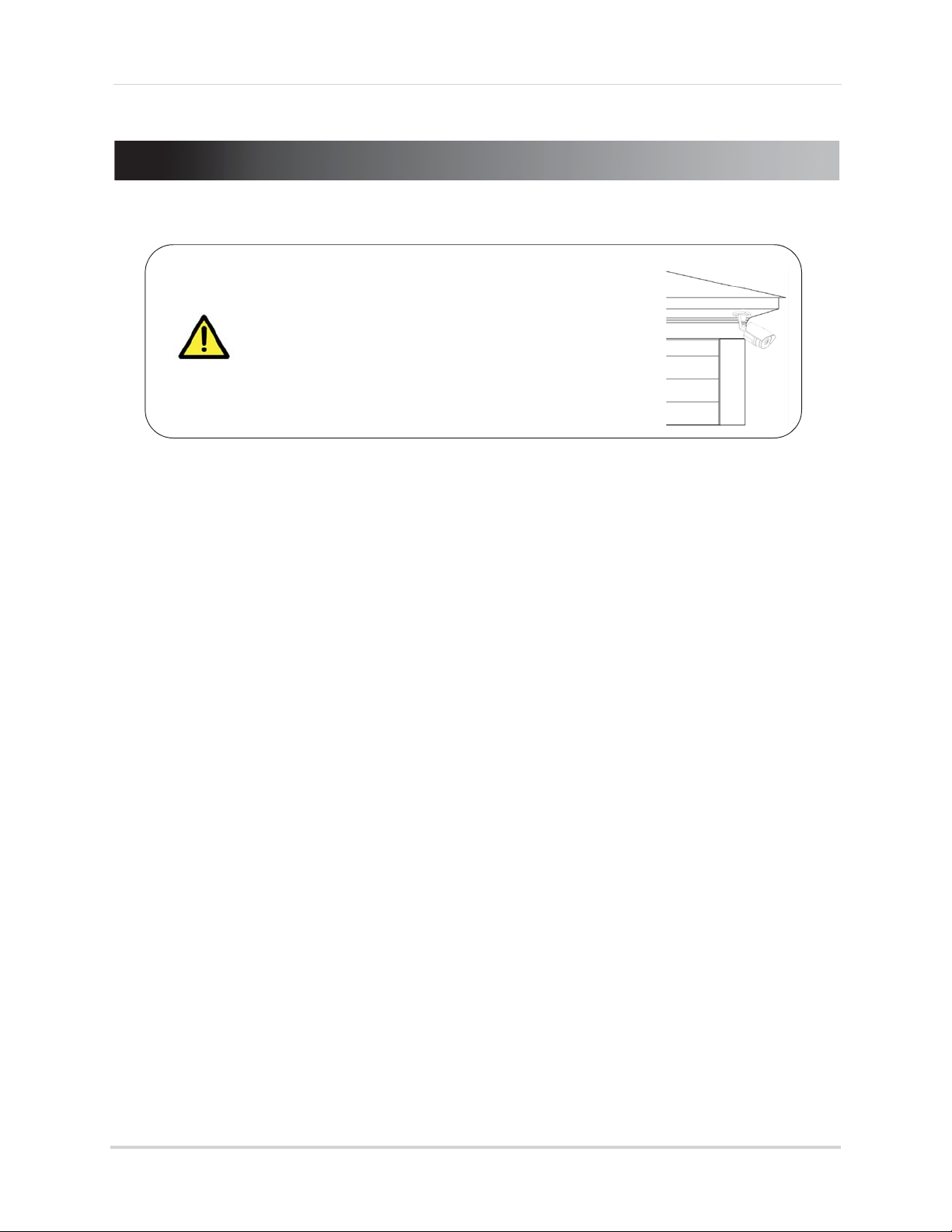
4. Installing the Camera
Camera is suitable for outdoor installation.
Installation in a sheltered location is
recommended. For example, install under shelter
protected from the elements, such as beneath roof
eaves. The diagram to the right shows an example of
an ideal location for outdoor placement.
4.1 Installation Warnings
• Aim the camera to optimize the viewing area: select a location that provides a clear view of
the area you want to monitor, that is free from dust, and that is not facing a strong light source
or direct sunlight.
• Avoid installing the camera where there are thick walls or obstructions between the camera
and the receiver.
• Avoid installing in a location which requires the wireless signal to pass through cement,
concrete, and metal structures. This will reduce the range of transmission. For details, see
“Appendix B: Frequently Asked Questions” on page 11.
• Select a location for the camera that has an ambient temperature between 14°F~122°F
(-10°C~50°C)
• Not intended for submersion in water. For outdoor use, installation in a sheltered location is
recommended.
4
Page 16

Installing the Camera
4.2 Mounting Positions
You may mount your camera on a wall, ceiling, or counter. See the images below for
recommended configurations of the camera stand and antenna.
Wall Ceiling
NOTE: For ceiling installation, position the antenna as high as the ceiling allows. See the
"Ceiling" mounting position in the figure above.
Before mounting the camera permanently, carefully plan where and
how the camera will be positioned and where you will route the cable
that connects the camera to the power adapter. Verify the camera’s
performance by observing the image on a monitor when the camera
is positioned where it will be permanently installed.
Counter
4.3 To Install the Camera
1 Use the included mounting screws to mount the camera to the mounting surface:
• Mark the positions of the screw holes
on the mounting surface.
• Drill holes and insert the drywall plugs
(included) as needed.
• Firmly attach the camera to the
mounting surface using the included
screws.
NOTE: If y
before firmly attaching the camera to the mounting surface.
NOTE: If y
power connector cable through the cable notch on the camera base before firmly
attaching the camera to the mounting surface.
ou are running the power cable through the mounting surface, connect power
ou are running the power cable along the mounting surface, you need to run the
Cable Notch
5
Page 17

Installing the Camera
2 Loosen the thumbscrews (1, 2) and the adjustment ring (3) by turning them counter
clockwise.
1
2
3
3 Adjust the angle of the camera until the desired view is set. Tighten the thumbscrews and the
adjustment ring to secure the camera’s position.
4 Co
nnect the power cable from the camera to the weatherproof power connector. Plug the
power adapter into a power outlet or surge protector.
NOTE: Power cables are only weatherproof when fully inserted at the connection point.
Power cables may not be submerged in water.
5 Remo
ve protective film from the camera lens to uncover the microphone. The protective
film may prevent the microphone from working if not removed.
6
Page 18
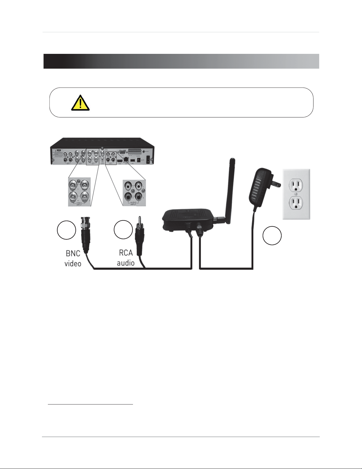
5. Connecting to a DVR
Before powering on the receiver, make sure to first connect and
power on the camera. This will ensure a proper connection.
Connecting to a DVR
1
2
3
1 Connect the BNC video cable from the receiver to the video input on your DVR.
2 Connect the RCA audio cable from the receiver to the corresponding audio input. The audio
input number or name should match the video input where you connect the BNC cable (e.g.
Video Input 1 and Audio Input 1).
3 Co
4 Plac
nnect the power cable to the power port on the receiver and plug it into a power outlet or
surge protector.
e the receiver where it will have clear reception to your camera
NOTE: If your camera is out of range, the pairing status LED will flash on and off rapidly.
OPTIONAL: Use
the double-sided tape to secure the receiver to a surface (e.g. wall).
1
.
1. Avoid installing in a location which requires the wireless signal to pass through cement, con-
crete, and metal structures. This will r
educe the range of transmission.
7
Page 19

Connecting to a TV
6. Connecting to a TV
1
2
3
1 Connect the included BNC-to-RCA adapter to the BNC connector on the receiver. Connect the
other end of the BNC-to-RCA adapter to the RCA video input on your television.
2 Co
3 Connect the power cable to the power port on the receiver and plug it into a power outlet or
4 P
5 Plac
nnect the RCA audio connector from the receiver to the audio input on your television.
surge protector.
ower on your television and select the input that the receiver is connected to.
e the receiver where it will have clear reception to your camera
1
.
1. Avoid installing in a location which requires the wireless signal to pass through cement, con-
crete, and metal structures. This will r
8
educe the range of transmission.
Page 20

7. Pairing Cameras
Pairing Status LED
Pair button
IMPORTANT
The camera and the receiver have already been paired out of the box, which
means that they are exclusively communicating with each other. If for some
reason the pairing is lost, follow these steps to pair the camera and receiver.
To pair the camera to the receiver:
1 Mak
2 Pr
e sure that the camera and receiver are both powered up and all antennas are properly
attached.
ess and hold the PAIR button on the receiver for 5 seconds to activate pairing mode.
The pairing status LED will flash on and off slowly.
Pairing Cameras
3 Press the PAIR button on the back of the camera within 30 seconds of pressing the PAIR
button on the receiver.
• If pairing is successful, live video from the camera will appear on the monitor.
Pair button
9
Page 21

Appendix A: System Specifications
8. Appendix A: System Specifications
8.1 General Specifications
TX Frequency Range 2.400GHz~2.480GHz
TX Power 16dBm
Unobstructed Effective Range 165ft (50m) indoor
500ft (152m) outdoor
Data Rate 4 Mb/s
Modulation GFSK
Spread Spectrum FHSS
Operating Temperature Range 14°F ~ 122°F / -10°C ~ 40°C
1. Maximum wireless transmission range. Actual range dependent upon building materials and other obstructions in path of
wireless signal.
8.2 Receiver Specifications
RX Sensitivity -81dBm
Demodulation GFSK
Supported Resolution VGA (640x480) up to 30 frames per second
Termination 1x BNC video, 1x RCA audio
Power Requirement 9V DC +/- 5%
Power Consumption 270mA Max
Dimensions (W x D x H) 53 x 137 x 86mm / 2.1 x 5.4 x 3.4" (with antenna attached)
Weight 0.1kg / 0.3lbs
1
8.3 Camera Specifications
Image Sensor Type 1/4" Color CMOS Image Sensor
Effective Pixels H: 640 V: 480
Image Compression MPEG4
Image Resolution VGA (640x480)
Lens 3.6mm F2.0
Field of View (Diagonal) 55°
AGC On
Power Requirement 9V DC +/- 5%
Power Consumption 430mA Max with IR LED
220mA Max without IR LED
Environmental Rating
IR LED Quantity / Type 24 pieces / 850nm
Night Vision Range
Built in Auto IR Turn On / Off CdS Drive Auto IR LED turn On/Off Circuit
Dimensions (W x D x H) 79 x 203 x 117mm / 3.1 x 8.0 x 4.6" (with antenna and sun-
Weight 0.3kg / 0.6lbs
1. Not intended for submersion in water. Installation in a sheltered area recommended.
2. Stated IR illumination ranges are based on ideal conditions in typical outdoor night time ambient lighting and in total
darkness. Actual range and image clarity depends on installation location, viewing area, and light reflection / absorption
level of object.
1
2
IP66
135ft (41m) / 90ft (27m)
shade)
10
Page 22

Appendix B: Frequently Asked Questions
9. Appendix B: Frequently Asked Questions
9.1 Wired vs. Wireless Cameras
A wired camera has a video cable that transmits the video signal from the camera to a
recording or viewing device.
A wireless camera does not use a video cable. Instead, it wirelessly transmits the video
signal to a wireless receiver that is connected to your DVR. Wireless cameras do not
require video cabling to be run between the camera and the DVR, which reduces
installation time and cost.
9.2 Does a wireless camera require power?
Yes. Wireless cameras require two power sources: one connected to the camera, and the
other to the receiver. The term "wireless" refers to the lack of a video cable between the
camera and the receiver.
9.3 How far can a wireless camera transmit a video signal?
In an open field (with line of sight), a typical wireless camera has a range between 250 - 500
feet. 'Line-of-sight' means that there are no obstructions between the camera and
receiver. Obstructions include walls, buildings, trees, and certain electronic devices.
Materials containing moisture (for example, leaves) may also act as an obstruction. Cubical
walls, drywall, glass, and windows generally do not degrade wireless signal strength.
In a closed environment—such as the interior of a house—the wireless camera range is
between 100 - 165 feet. The signal range varies depending on the type of building materials
or objects the wireless signal must pass through. The signal range also depends on
whether there are competing signals using the same frequency as the camera. For
example, signals from cordless phones or routers may affect signal strength. Adaptive
Frequency Hopping Spread Spectrum (FHSS) technology featured in the latest Lorex
models greatly reduce signal interference.
Range Limiting Factors
Reflection
The signal
reflects back
1
Source: Xirrus (2010). "Wi-Fi Range Dynamics".
Retrieved online at http://xirrus.gcsmarket.com/pdfs/Xirrus_Wi-Fi_Range.pdf
The signal scatters
back into multiple
new signals
1
Scattering
Refraction
The signal bends
as it travels
through an
object (e.g. glass
window)
Diffraction
The signal
changes direction
as it passes
around an object
Attenuation
The signal
strength weakens
as it passes
through an object
11
Page 23

Appendix B: Frequently Asked Questions
Material Signal Reduction (%)
Plaster & Wood 10 - 30%
Brick 30 - 50%
Concrete Cinder Blocks 50 - 70%
Metal & Metal Cladding 70 - 90%
NOTE: Signals that must pass through wet or moist materials
(e.g. shrubs and trees) may be significantly reduced.
Signal Reduction Through Materials
Signal strength decreases as it passes through different types of material. The table below
shows how signals become reduced when passing through different materials:
The stronger the signal strength, the higher the video frame rate. The lower the signal
strength, the lower the video frame rate.
Full signal strength
(high frame rate)
Low signal strength
(low frame rate)
9.4 Are digital wireless camera signals secure?
Yes. Lorex digital wireless products feature a wireless transmission method called
Frequency Hopping Spread Spectrum (FHSS). This type of signal is highly resistant to
eavesdropping as it generates a channel hopping sequence using an algorithm generated
by the receiver, which only the camera can follow through the "pairing" function.
Pairing is an electronic handshake between dig
ital wireless devices. Digital wireless
cameras can only be paired to one receiver. This is to prevent interception by third parties,
and prevents any other device from picking up the signal—this also means that you cannot
pair one camera to multiple receivers.
9.5 How many frames per second should I expect from a digital
wireless camera?
Current Lorex digital wireless cameras offer 10 - 30 FPS (Frames Per Second)
performance. Actual frame rate depends mainly on signal strength (see the chart in
section above).
For details on supported resolutions and frame rates for this model, see “Appendix A:
System Specifications” on page 10.
9.6 How many wireless cameras can I install?
It is recommended to install a maximum of 4 wireless cameras per system (4 receivers and
4 cameras). Minimum space between receivers should be 4 inches / 10cm and minimum
space between cameras should be 6.5ft / 2m to minimize potential signal strength
degradation.
12
Page 24

Appendix C: Troubleshooting
10. Appendix C: Troubleshooting
If you have problems with your system, there is often a quick and simple solution. Please
try the following:
Problem Solution
There is no picture from the
camera(s)
There is no audio from the
camera(s)
The picture is dropping • Move the camera closer to the receiver.
The picture is or has become
choppy
• Make sure that the camera is plugged into a power outlet and that
the power adapter is plugged in properly.
• Make sure receiver is plugged into a power outlet.
• Move the camera closer to the receiver.
• Make sure BNC video output cable is connected to your DVR or
levision.
te
• If you are viewing your camera(s) using a TV, make sure you have
correct input selected.
the
• Make sure the RCA audio output cable is connected to your DVR
or television audio input.
• Make sure audio recording is enabled on your DVR. See your DVR
manual f
• Make sure to remove the protective film from the camera lens. The
mi
properly if the protective film is left on.
• Try repositioning the camera, receiver, or both to improve the
re
• The picture may become choppy when experiencing a lower frame
rate (e.g. 6 frames per second vs. a higher 20 frames per second).
• Try moving the camera closer to the receiver.
• Remove obstructions between the receiver and camera.
or further instruction.
crophone is located on the front of the camera and will not work
ception.
The picture is white • "Washout" or "white wash" can occur when a strong light source
is point
during a white wash.
• Do not point your camera towards a bright light source.
The picture is too dark • If using during the day, the camera may not be getting enough
li
The picture is too bright • If using during the day, the camera may be getting too much light.
Reconsider the position of your camera.
Night vision is not working • Night vision activates when light levels drop. The area may have
t
Bright spot in video when
viewing camera at night
• Night vision reflects when pointing a camera at a window. Move
the c
ed at the camera lens. The camera lens is not harmed
ght. Reconsider the position of your camera.
oo much light.
amera to a different location.
13
Page 25

Appendix D: Extending Wireless Signal Range
11. Appendix D: Extending Wireless Signal
Range
DISCLAIMER: Certain accessories are not available in all markets.
There are several ways to boost your wireless signal as well as options to help you extend
the range of the wireless signal.
Clear Line-of-Sight
You should always try to ensure there is a clear line-of-sight between the camera and the
receiver.
Clear line of sight
Receiver
Extending Your Wireless Signal
Even with a clear line-of-sight between your camera(s) and your receiver(s), you may
experience a lower video frame rate simply due to the distance between your wireless
devices.
Accessory antennas are available that can help extend the
range of your wireless signal.
14
Page 26
Appendix D: Extending Wireless Signal Range
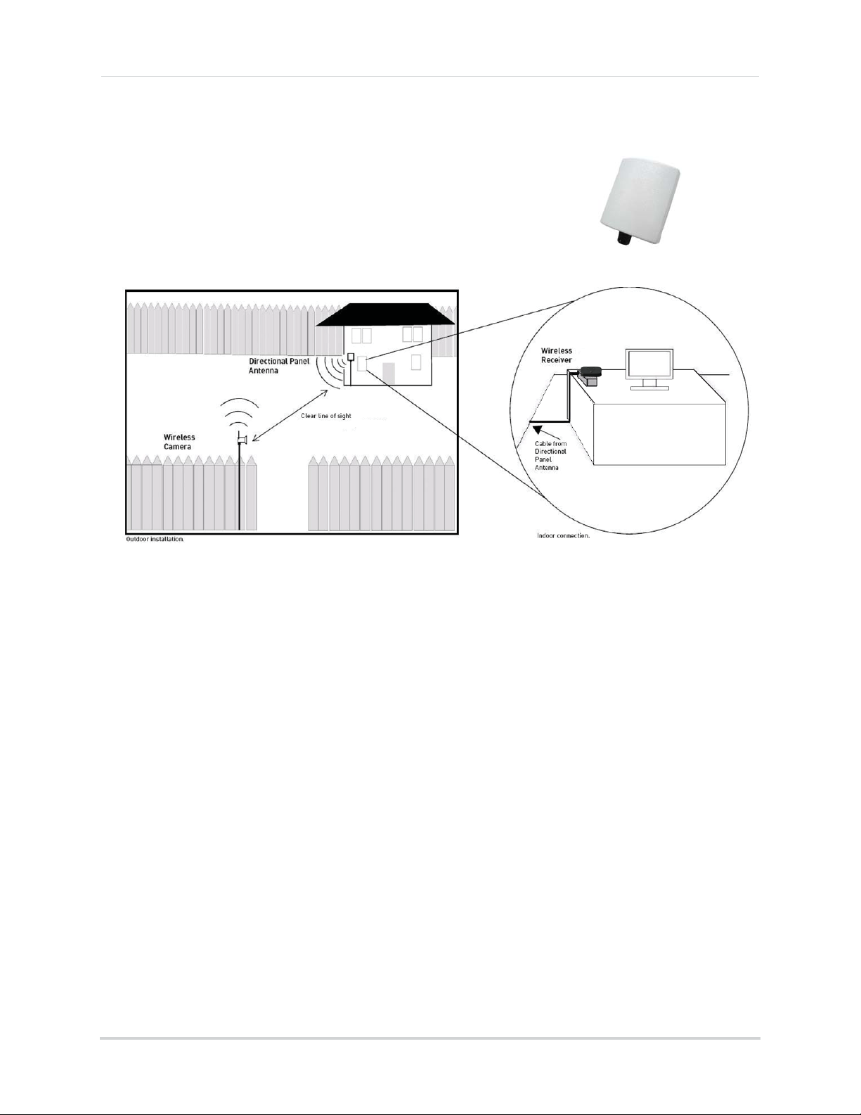
2.4 GHZ Directional Wireless Panel Antenna
Use the 2.4GHz Directional Wireless Panel Antenna
(model #: ACCA
camera in order to increase the range of transmission
(clear line-of-sight
required). A 20ft extension cable is included to help to
properly position the antenna.
NTD9) to focus a
between the camera and the antenna is
wireless signal onto the
Directional Wireless Panel Antenna
Scenario 1: Single Receiver Installation
Attach a directional antenna to the camera and/or the receiver. It is recommended to
attach the antenna to the receiver and place it in a location that has clear line-of-sight to
the camera. Ensure that the directional antenna is pointing toward the other antenna. For
example, if the directional antenna is connected to your receiver, the directional antenna
should point at the camera (see figure above). During the installation, check the reception
on your DVR.
Scenario 2: Multiple Camera / Receiver Installation
If you are using multiple wireless cameras and receivers in your installation, attach
directional antennas to the camera(s) and receiver(s) that are farthest away from each
other. Follow these guidelines to increase the signal strength between your cameras and
receivers:
• Point directional antennas towards the receiver for each camera.
• Keep as much space as possible between each receiver.
• Keep as much space as possible between directional antennas if using more than one.
• Minimize the amount of obstructions (e.g. walls or trees) between the antennas and receivers.
• During the installation, check the reception of each camera on your DVR.
Visit www.lorextechnology.com for more det
ails on wireless antennas and accessories.
15
Page 27

LW2231
Version 1.0
www.lorextechnology.com
Copyright © 2013 Lorex Technology Inc.
Page 28

Note : Cet appareil est conforme à la Partie 15 des règlements de la FCC et aux normes RSS de
l’Industrie du Canada. Son fonctionnement est soumis aux deux conditions suivantes : (1) cet
appareil ne doit pas causer des interférences nuisibles, et (2) cet appareil doit accepter toute
interférence reçue, y compris les interférences qui peuvent provoquer un fonctionnement
indésirable.
Le fabricant n'est pas responsable des toutes interférences radio ou télévision causées par des
modifications non autorisées apportées à cet appareil. De telles modifications peuvent empêcher
l’utilisateur d’utiliser l'appareil.
THIS DEVICE COMPLIES WITH PART 15 OF THE FCC RULES AND INDUSTRY CANADA
LICENSE-EXEMPT RSS STANDARD(S). OPERATION IS SUBJECT TO THE FOLLOWING TWO
CONDITIONS: (1) THIS DEVICE MAY NOT CAUSE HARMFUL INTERFERENCE, AND (2) THIS DEVICE
MUST ACCEPT ANY INTERFERENCE RECEIVED, INCLUDING INTERFERENCE THAT MAY CAUSE
UNDESIRED OPERATION.
THE MANUFACTURER IS NOT RESPONSIBLE FOR ANY RADIO OR TV INTERFERENCE CAUSED BY
UNAUTHORIZED MODIFICATIONS TO THIS EQUIPMENT. SUCH MODIFICATIONS COULD VOID THE
USER’S AUTHORITY TO OPERATE THE EQUIPMENT.
 Loading...