

Page 1

Page 2

Features
·Digital Wireless Technology Provides Excellent Image Quality and Clarity
·Interference Free, secure and private signal.
·Up to 300ft Wireless Transmission Range*
·Listen in with Exceptional Sound Clarity
·T wo-way Audio
*Maximum open space transmission range. The actual range is dependent upon
building materials and other obstructions in path of wireless signal.
Receiver Features
·2.4’’Color LCD Monitor /Receiver with Superior Image Quality
·Rechargeable Lithium Polymer Battery for True Portability
·Sound trigger alarm
·Low Power indicator
Camera Features
·Night Vision allows for low light viewing up to 15 Feet/4.5meters**
·Built-in Microphone
·Camera can be battery operated for true portable wireless operation***
·Built-in speaker to hear from monitor
**IR illumination range of 15ft./4.5m under ideal conditions. Objects at or beyond this
range may be partially or completely obscured, depending on the camera application.
***The rechargeable battery pack is optional at extra cost.
The Digital Wireless signal transmission type used in this digital unit is also known
as FHSS-Frequency Hopping Spread Spectrum. This type of signal is highly
resistant to deliberate jamming as it generates a channel hopping sequence using an
algorithm generated by the receiver system.
- 1 -
Page 3

Getting Started
The system comes with the following components:
1x Wireless Receiver 1x Receiver Cradle 1x Wireless Camera
1x Power Adapter for Receiver 1x Power Adapter for Camera
Check your package to confirm that you have received the complete system, including all
components shown above.
- 2 -
Page 4

Wireless Receiver
Front Controls
1. Receiver Antenna-Receives &
Sends signals from or to the Camera.
2. Power /Low Power Indicator-The
left Green LED indicates the Receiver
Power is ON or OFF. The Red LED’s
flash to indicate the power is low.
3. LCD Screen-Displays video from
the Camera.
4. P/S Button-When the P/S button is pressed, the LCD Screen is turned off. The P/S
feature can be used for the following two reasons: (1) To prevent the user from being
disturbed (i.e. when sleeping) by the bright LCD screen, or (2) To conserve battery power.
If audio is detected above the preset audio trigger level on the Camera, the Receiver will
beep and display the Camera. The receiver will return to P/S mode about 5 seconds after
the Alarm has completed. Press P/S while the screen is off, or press any other key in the
front panel while the screen is on will cancel this mode.
5. Navigation Controls-Use the controls in Viewing Mode.
Viewing Mode: The following controls are used while watching live video from the
camera:
Press the UP/DOWN buttons to Increase or Decrease the volume.
Press the LEFT/RIGHT butters to decrease or increase the EV.
6. Talk-Press and hold the button in Viewing Mode to talk with the baby.
7. Microphone-Receives sounds for the area near the receiver, and transmits the sound
from the receiver to the camera.
8. Speaker-Produces the sound transmitted from the Camera.
9. Stand-Flip the stand out to place the receiver on a flat surface (such as a table or
countertop). Alternatively , place the receiver in the Receiver Cradle.
Bottom Control
10. Pair Button-Press the Pair button when pairing
the Receiver with a Camera.
- 3 -
Page 5

Side Controls
11. Alarm +/-Button-Press to increase or
decrease the volume of the audio alarm.
12. Power Button-Slide to turn the Receiver
ON or OFF.
13. DC 5V Power Input-Connect the included
DC5V Power Adapter to power the receiver
and/or charge the Receiver battery (When the
receiver is not in the Cradle).
Receiver Cradle Inputs
14. DC 5V Power Input –Connect the DC 5V
Power Adapter (included) to the Receiver
Cradle to power the receiver and/or charge the
Receiver (when docked).
Wireless Receiver Installation
Determine if you will be using the Receiver Cradle, or connecting the cables directly to the
receiver before installation:
1. Place the Receiver Cradle or Receiver in a place that will have clear reception with your
camera.
2. Plug the AC adapter power output cable into the 5V POWER input of the Cradle or
Receiver.
Plug the power plug into a wall outlet or surge protector.
3. Leave the receiver to charge for 6hours prior to first time use so the built-in
rechargeable receiver battery is fully charged. DO NOT remove the power cable from the
receiver / from the cradle during initial charging process .After initi al charge, charge as
required.
Camera
Front & Back
1. Camera Antenna-Receives &
Sends signals to or from the
Receiver.
2. Lens/IR LED-Infrared LEDs
provide viewing in no/low light
conditions.
- 4 -
Page 6
3. Microphone-Receives sounds for the area near the camera, and transmits sound from the
Camera to the Receiver.
4. Speaker-Produces the sound transmitted from the receiver.
5. PAIR Button-The pairing button is located on the back of the camera behind the stand
mount
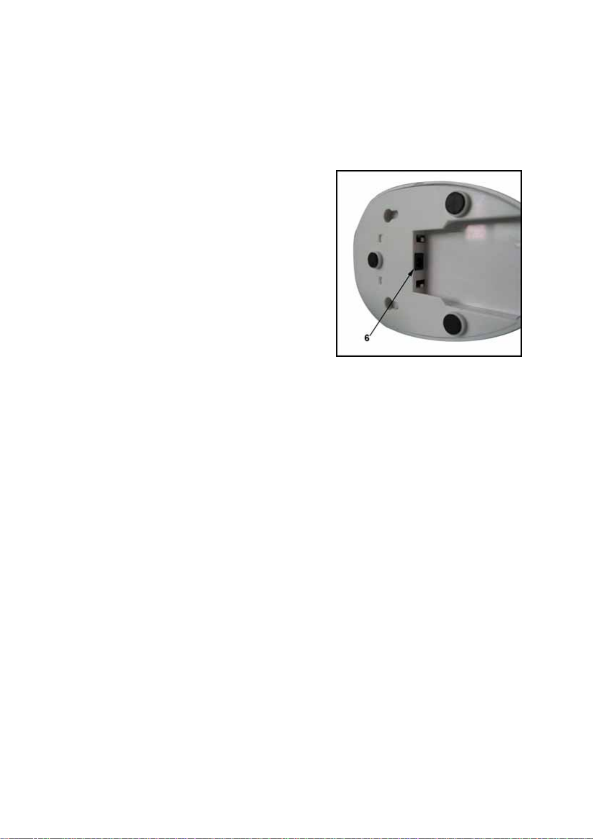
6. DC 9V Power-Connect the DC 9V Power
Adaptor to the Camera.
NOTE: The camera can also be powered by the
optional rechargeable battery pack. If the camera is
plugged in with the AC adapter, the battery pack
will not be used. the battery pack is intended for
short term, potable camera use.
Camera Installation
Before you install the camera, carefully plan where and how it will be positioned, and
where you will route the cable that connects the camera to the power adaptor.
Before starting permanent installation, verify its performance by observing the image on
the receiver when camera is positioned in the same location/position where it will be
permanently installed and the receiver is places in the location where it will be used most
of the time.
Installation W arnings
Aim the Camera to best optimize the viewing area: Select a location for the camera that
provides a clear view of the area you want to monitor, which is free from dust, and is not in
line-of-sight to a strong light source or direct sunlight.
Avoid installing the camera where there are thick walls, or obstructions between the
Camera and the Receiver.
Night Vision
This camera has built-in IR LEDs, which provides the camera with ability to view images
in no/low light conditions. It is important to use the provided power adapter (and not the
battery pack) when using the camera for prolonged periods in low light conditions ,as the
built-in IR LEDs will drain the battery more quickly than regular daytime use.
Adjust EV to get the best image while the IR LEDs is on.
- 5 -
Page 7

Sound Trigger
When the sound detected by the camera is above preset level*, the monitor will be
triggered to alarm. This will happen in two circumstances, 1) the monitor is in P/S mode, 2)
the monitor is in MUTE** mode.
*The level is preset by manufacturer, can not be adjusted by users.
**When the sound detected by camera is under a preset level(preset by manufacturer
only, a very low level), the monitor will shut down the speaker so that you won’t get
disturbed by environmental noise. This is MUTE mode.
Install the Camera
1. Carefully unpack the Camera.
2. Mount the camera to the wall:
Mark the position of the screw holes on the wall.
Drill holes and insert 2 screws.
Firmly attach the camera to the wall by placing
the stand over the installed screws and pushing the
base downwards to secure.
NOTE:
surface, such as a Table or Shelf, and no mounting
hardware is required.
3. Adjust the Viewing angle of the Camera.
The camera can also be placed on a flat
Connecting Camera Power
The Camera can be powered either by using the provided Power Adapter, or using
rechargeable battery pack(not included).
NOTE: Wireless camera requires a power source (either an electrical outlet or battery
power) to operate.
If you plan to permanently mount the camera in a location, it is recommended to use the
included Camera Power adapter to prevent interruptions in the image, as using battery
power is intended as a temporary power solution.
Camera Positioning
The Camera can be placed on a flat surface, or
wall mounted. The versatile stand allows for
several different mounting options.
- 6 -
Page 8

Viewing Mode
1. SIGNAL INDICATOR-The signal indicator
shows the strength of the signal being received
from the camera. The number of bars in the
Signal Indicator shows the strength of the
signal-One or No Bars indicates the signal is poor,
and 4 bars indicate a very strong signal.
2. Talk Indicator-Press Talk button in viewing
Mode, this indicator will show up, then you can
talk.
3. Night vision indicator-when the Night vision of camera turns on, it will show up.
Low Signal/No Signal Warnings
When the Camera is positioned too far from the
Receiver, warning messages will be displayed:
NO SIGNAL: The “No Signal” message means
the receiver cannot access the camera. Please
reposition the camera, or check the Camera
power.
Camera Pairing
The System comes with camera that has already been paired. This camera will
communicate with the receiver once powered on.
NOTE: It is highly recommended to pair the Camera to the Receiver before permanently
mounting the Cameras.
1. Power on the Camera by connecting the Power Adapter or Battery Pack. The power LED
for the Camera should be ON.
2. Power on the Receiver by connecting the power adaptor to the 5V Input on the side. Turn
on the receiver.
3. Press the PAIR button located on the bottom of
the Receiver using a pen tip or paperclip.
- 7 -
Page 9

4. A message will be displayed on the Receiver
screen.
The Receiver will count down from 30~0-you
must press the PAIR button on the Camera during
this time to successfully pair the Camera.
If the button on the Camera is not pressed, the
Receiver will return to the view screen, and no
pairing will take place.
5 .Press the PAIR button on the back of the
Camera
Once the camera has been paired, it will be
immediately viewable on the Receiver Monitor.
Troubleshooting
If you have problems with your System, there is often a quick and simple solution. Please
try the following:
Problem Solution
There is no picture from a Camera. Check all connections to the Camera. Make sure the
adapter is plugged in.
Make sure that the Camera and receiver are both ON.
Make sure that the camera is in range of the Receiver.
If using the battery pack, try charging the pack.
The picture is dropping Move the camera closer to the receiver.
Try repositioning the camera, receiver or both to
improve the reception
There are problems with the Audio Make sure that there is sound within range of the
Camera Microphone
If the unit emits a loud screeching noise (feedback),
move the camera or receiver farther apart.
The Picture is or has become
Choppy
The picture may become choppy when experiencing
a lower frame rate (i.e. 10 frames per second vs. a
higher 20 frames per second).Try moving the camera
closer to the receiver. Remove obstructions between
the Receiver and Camera.
- 8 -
Page 10

Specifications
Receiv
Receiving Frequency Range 2.405GHz~2.470GHz
Data Rate
Receiving Sensitivity
Demodulation Type
Resolution
Viewing Angle
A/V Output / Resolution
Alarm Sensitivity
Power Requirement
Power Consumption 400mA Max without charging, 800mA with charging
Operating Temp Range
Operating Humidity
Camer
Transmit Frequency Range
Data Rate
Transmitting Power
Modulation Type
Transmitting Distance
Image Sensor Type
Effective Pixels
Image Processing
Image Resolution / Frame Rate QVGA / 25FPS Max.
AES
White Balance
AGC / Range
Lens
Viewing Angle (Diagonal)
Minimum Illumination
IR LED / Night Vision Range
Power Requirement
Power Consumption
Operating Temperature
Operating Humidity
Environmental Rating
Dimensions(W x D x H)
er
a
4
4 Mbps
-81dBm
GFSK with FHSS
H: 480 V: 240
H: 50°
QVGA 320x240 / 25FPS
80dB ±10% (1M)
5V DC ±5%
14°F ~ 140°F / -1
10% ~ 85% RH
V:
2.405GHz~2.470GHz
Mbps
14dBm (Max)
GFSK with FHSS
100m (Line of Sight)
1/6” Color CMOS Image Sensor
H: 640 V: 480
Motion JPEG
On 1/2000 ~ 1/20 sec
Yes
On / 0dB~24dB
2.9mm / F1.8
61°
2.5 LUX (IR Off), 0 LUX (IR On)
8 LEDs / 840nm 4.5m (with IR LED)
9V DC ±5%
360mA MAX (IR on), 300mA (IR off)
14°F ~ 104°F / -10°C ~ 40°C
0% ~ 85%
14°F ~ 140°F / -10° ~ 60° C
2.6” x 5.7” x 3.3” / 66mm x 145mm x 84mm
50°
0℃ ~ 60℃
- 9 -
Page 11

FCC/IC Statement
This device complies with Part 15 of the FCC Rules.
Operation is subject to the following two conditions: (1) this device may not cause harmful
interference, and (2) this device must accept any interference received, including
interference that may cause undesired operation.
THE MANUFACTURER IS NOT RESPONSIBLE FOR ANY RADIO OR TV
INTERFERENCE CAUSED BY UNAUTHORIZED MODIFICATIONS TO THIS
EQUIPMENT. SUCH MODIFICATIONS COULD VOID THE USER
TO OPERATE THE EQUIPMENT.
Operation is subject to the following two conditions: (1) this device may not cause
interference, and (2) this device must accept any interference, including interference that
may cause undesired operation of the device."
This Class [B] digital apparatus complies with Canadian ICES-003.
Cet appareil numérique de la classe [B] est conforme à la norme NMB-003 du Canada.
S AUTHORITY
- 10 -
 Loading...