

RDF PRODUCTS
17706 NE 72nd Street
Vancouver, Washington, USA 98682
Tel: +1-360-253-2181 Fax: +1-360-635-4615
E-Mail: mail@rdfproducts.com
Web Site: www.rdfproducts.com
OPERATOR'S MANUAL
DFA-1325B2 60-1,000 MHz FIXED-SITE
DIPOLE ADCOCK DF ANTENNA
Rev A03/07-15/dfa1325b2_opm_01
Copyright © 2015 by RDF Products
Original Writing: October 2013

WARNING
Please comply with the following basic rules of safety and common sense to ensure safe installation
and operation as well as long product service life:
1. LIGHTNING PROTECTION
- Lightning strikes can cause death or serious injury to operating
personnel and destruction of equipment if appropriate precautions are not taken. It is essential
that the DFA-1325B2 be installed with the lightning protection precautions discussed in Section
V-G and Appendix C.
2. ELECTRICAL POWER LINES
- Never install the DFA-1325B2 in the immediate vicinity of
electrical power lines. If the antenna comes in contact with power lines, death or serious injury
to operating personnel is likely to result. See Section V-H.
3. INSTALLATION ISSUES - The user must provide a mast mount for the DFA-1325B2 as
discussed in Section V. In addition, the user must securely guy the unit for maximum safety.
Please study Section V carefully and take all necessary steps to ensure that the DFA-1325B2
is safely mounted. If there is any doubt regarding the safety of the installation, obtain
professional help as required as per Section V-A.
4. ELECTROSTATIC DISCHARGE (ESD) ISSUES - Although all RDF Products DF antennas and
DF processors are designed to minimize vulnerability to electrostatic discharge (ESD) induced
damage, fixed-site DF systems are especially prone to this hazard. Do not connect the DFA-
1325B2 to the DF receiver/processor before studying and complying with the necessary system
grounding and procedural precautions discussed in Section V-I.
5. EXTERIOR WEATHER-SEALING
enhance weather-sealing and prevent water intrusion. For longest product service life, do not
break the integrity of these exterior weather-seals.
Check the RDF Products website at www.rdfproducts.com for updates and bulletins.
Can we improve this manual? Contact us at mail@rdfproducts.com
- Sealants have been applied to the DFA-1325B2 exterior to
to offer suggestions.

mail@rdfproducts.com -- Copyright © 2015 by RDF Products -- www.rdfproducts.com
TABLE OF CONTENTS
SECTION I - GENERAL DESCRIPTION .................................................................. 1
SECTION II - SPECIFICATIONS .............................................................................. 3
SECTION III - PRE-ASSEMBLY INFORMATION .................................................... 5
A. UNPACKING AND INSPECTION ...................................................................... 5
B. EQUIPMENT SUPPLIED ................................................................................... 5
C. EQUIPMENT REQUIRED BUT NOT SUPPLIED .............................................. 6
SECTION IV - ASSEMBLY ....................................................................................... 7
A. INTRODUCTION ................................................................................................ 7
B. STEP-BY-STEP ASSEMBLY INSTRUCTIONS ................................................. 8
SECTION V - INSTALLATION ................................................................................. 13
A. GENERAL .......................................................................................................... 13
B. SELECTING A DF SITE ..................................................................................... 13
C. MOUNTING THE MAST SUPPORT PIPE ......................................................... 14
D. INSTALLING THE DFA-1325B2 ON THE MAST SUPPORT PIPE ................... 14
E. ORIENTATION ISSUES ..................................................................................... 16
F. SITE CALIBRATION .......................................................................................... 17
G. LIGHTNING PROTECTION ............................................................................... 19
H. ELECTRICAL POWER LINES ........................................................................... 19
I. ELECTROSTATIC DISCHARGE (ESD) ISSUES .............................................. 19
SECTION VI - MAINTENANCE ................................................................................ 21
SECTION VII - SIMPLIFIED THEORY OF OPERATION .......................................... 23
APPENDIX A - INTERFACE CABLE MATING CONNECTOR PIN-OUT ................. 25
APPENDIX B - INTERFACE CABLE EXTENSIONS ................................................ 26
APPENDIX C - MORE ON LIGHTNING PROTECTION
........................................... 28
iii

mail@rdfproducts.com -- Copyright © 2015 by RDF Products -- www.rdfproducts.com
LIST OF ILLUSTRATIONS
Figure 1 - DFA-1325B2 60-1,000 MHz H/Sleeve-Dipole Adcock DF Antenna .. 1
Figure 2 - DFA-1325B2 Major Components ...................................................... 6
Figure 3 - DFA-1325B2 Hardware Close-Up ..................................................... 6
Figure 4 - Inserting the Cable into the Mast ...................................................... 8
Figure 5 - Installing the Mast Flange onto the Main Chassis ............................ 8
Figure 6 - UHF Sleeve-Dipole Array Installation ................................................ 9
Figure 7 - Turnbuckle Fastener Detail ............................................................... 9
Figure 8 - Kevlar Guy Tie-Down Detail .............................................................. 9
Figure 9 - Watson-Watt DF System Simplified Functional Block Diagram ........ 23
Figure 10 - Adcock DF Antenna Azimuthal Gain Patterns ................................... 24
Figure 11 - Interface Cable Mating Connector Pin-Outs ...................................... 25
iv
mail@rdfproducts.com -- Copyright © 2015 by RDF Products -- www.rdfproducts.com
SECTION I - GENERAL DESCRIPTION
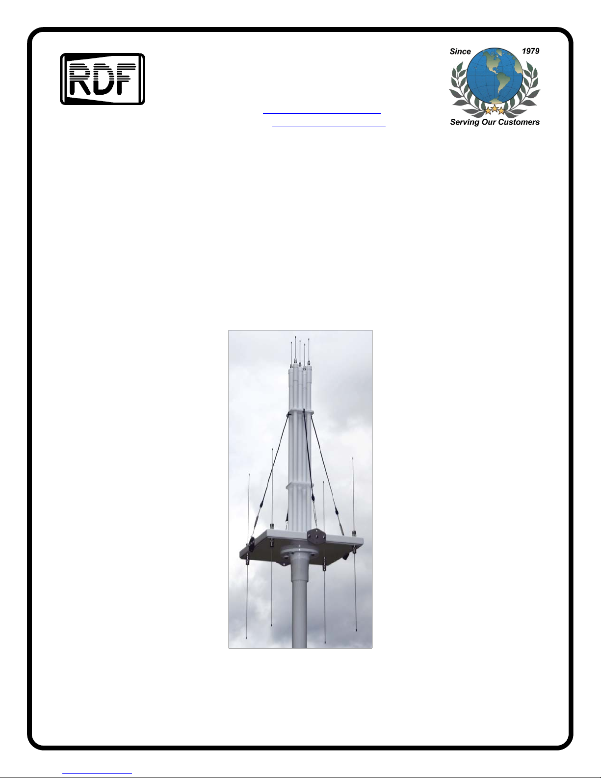
The RDF Products Model DFA-1325B2 is a dual-array VHF/UHF
H/sleeve-dipole Adcock single-channel radio direction finding
antenna covering 60-1,000 MHz in two bands. This rugged,
weather-sealed unit is specifically designed for permanent or
transportable fixed-site DF applications and is readily mast- or
tower-mounted.
Being of a true Adcock design, the DFA-1325B2 avoids the erratic
performance associated with inferior loop DF antennas and
provides sensitivity and listen-thru capability superior to that of
comparable pseudo-Doppler DF antennas. The DFA-1325B2 has
also been designed for high signal-handling capability for reliable
performance in dense signal environments. It is a particularly
good choice for tactical military, signal intelligence, and frequency
management applications where ultra-wide frequency coverage is
required.
The DFA-1325B2 has been specially designed so that its
performance is independent of its supporting mast or tower. (This
is accomplished with the supplied isolation mast.) This is in sharp
contrast to competing mast-mounted DF antenna designs where
performance is adversely and unpredictably affected not only by
the presence of the mast, but also by changes in mast height.
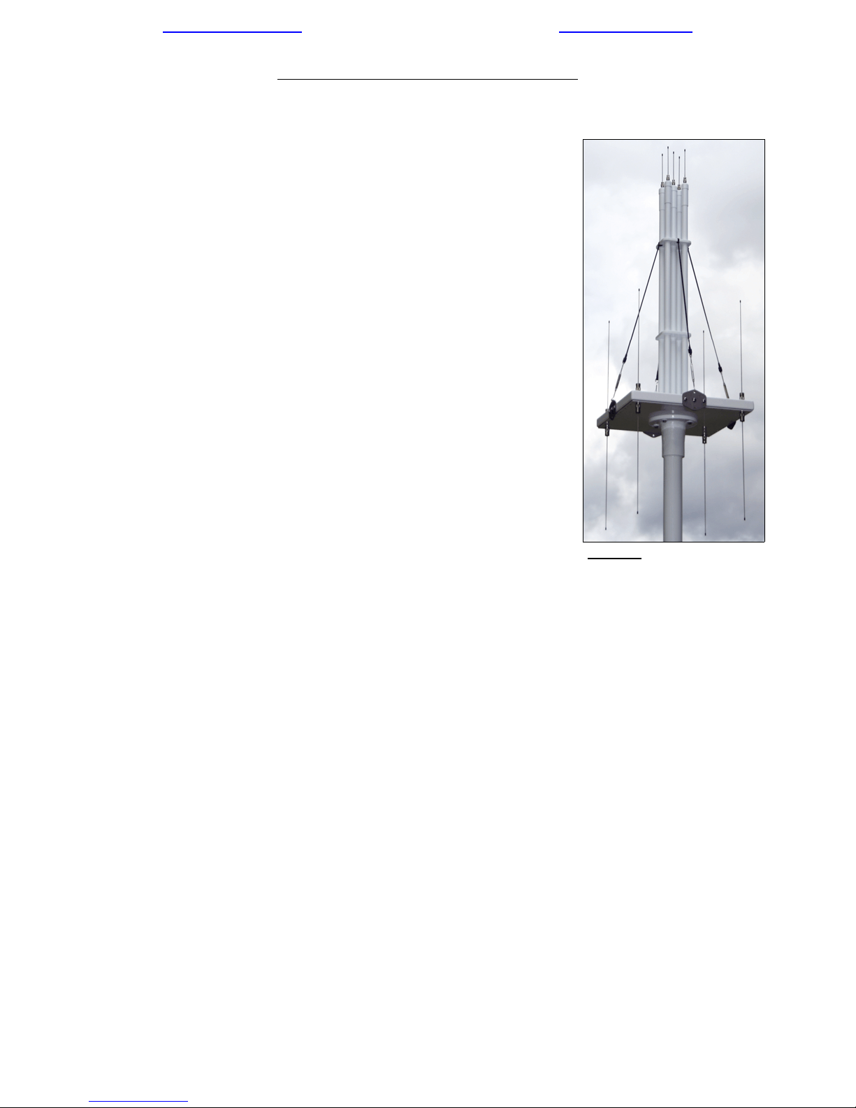
Figure 1 - DFA-1325B2 60-
1,000 MHz H/Sleeve-Dipole
Adcock DF Antenna
The DFA-1325B2 directly interfaces with all RDF Products DF
receivers and bearing processors via a single 8-meter interface cable set (routed through the
isolation mast). Custom interface cables with user specified lengths are also available. The
aerials are removable to facilitate storage, transport, and user testing. The isolation mast can
likewise be removed.
The DFA-1325B2 includes a digital “personality module” that reports model number and
frequency coverage information for this DF antenna. When connected to any of the RDF
Products “B”-series DF processors/receivers (e.g., the DFP-1000B, DFP-1010B, DFR-1000B,
or DFR-1200B), the DFA-1325B2 automatically reports its model number and frequency
coverage information. This information is then displayed so that the user can easily avoid outof-band operation.
1 of 29 - RDF Products - Vancouver Washington USA

mail@rdfproducts.com -- Copyright © 2015 by RDF Products -- www.rdfproducts.com
NOTES
_______________________________________________________________________
_______________________________________________________________________
_______________________________________________________________________
_______________________________________________________________________
_______________________________________________________________________
_______________________________________________________________________
_______________________________________________________________________
_______________________________________________________________________
_______________________________________________________________________
_______________________________________________________________________
_______________________________________________________________________
_______________________________________________________________________
_______________________________________________________________________
_______________________________________________________________________
_______________________________________________________________________
_______________________________________________________________________
_______________________________________________________________________
_______________________________________________________________________
_______________________________________________________________________
_______________________________________________________________________
_______________________________________________________________________
_______________________________________________________________________
_______________________________________________________________________
_______________________________________________________________________
2 of 29 - RDF Products - Vancouver Washington USA

mail@rdfproducts.com -- Copyright © 2015 by RDF Products -- www.rdfproducts.com
SECTION II - SPECIFICATIONS
DF Technique: Single-channel 2-phase Adcock (mixed sense).
Frequency Coverage: 60-200/200-1,000 MHz continuous (two bands).
Bearing Accuracy: 3.0/5.0E RMS maximum; 2.5/4.0E RMS typical (V/UHF; ideal
siting conditions).
Polarization: Vertical.
Output Impedance: 50 ohms nominal.
2nd Order Intercept: +40/+28 dBm typical (V/UHF; referred to sense input).
3rd Order Intercept: +25/+13 dBm typical (V/UHF; referred to sense input).
Required X & Y Axis 1.0 volts p-p (+/-5%), sinusoidal (100-2000 Hz)
Encoding Tone Voltages:
Personality Module: Reports antenna model and frequency coverage information as
300N81 RS-232 data string “DFA-1325B-2, 60-200, 200-1000
<CR><LF>”.
Power Requirements: 11-16 VDC @ 300 mA (negative ground).
Operating Temperature: -40 to +60 degrees C.
Storage Temperature: -40 to +70 degrees C.
Humidity: 0-100%.
Maximum Wind Velocity: 80 mph.
Dimensions: 118.75"x20.75"x20.75" (HxWxD, including 5' isolation mast, and
2' stainless-steel mast support pipe).
Weight: 63.5 lbs. (structural weight including main chassis, aerials,
isolation mast, and 8-meter interface cable; excluding 14 lbs.
stainless-steel mast support pipe and external guy lines).
3 of 29 - RDF Products - Vancouver Washington USA

mail@rdfproducts.com -- Copyright © 2015 by RDF Products -- www.rdfproducts.com
NOTES
_______________________________________________________________________
_______________________________________________________________________
_______________________________________________________________________
_______________________________________________________________________
_______________________________________________________________________
_______________________________________________________________________
_______________________________________________________________________
_______________________________________________________________________
_______________________________________________________________________
_______________________________________________________________________
_______________________________________________________________________
_______________________________________________________________________
_______________________________________________________________________
_______________________________________________________________________
_______________________________________________________________________
_______________________________________________________________________
_______________________________________________________________________
_______________________________________________________________________
_______________________________________________________________________
_______________________________________________________________________
_______________________________________________________________________
_______________________________________________________________________
_______________________________________________________________________
_______________________________________________________________________
4 of 29 - RDF Products - Vancouver Washington USA

mail@rdfproducts.com -- Copyright © 2015 by RDF Products -- www.rdfproducts.com
SECTION III - PRE-ASSEMBLY INFORMATION
A. UNPACKING AND INSPECTION
Carefully examine the shipping carton for damage before it is opened. If damage is evident,
have the carrier’s agent present, if possible, when the equipment is unpacked. If the carrier’s
agent cannot be present, retain the cartons and packing material for the carrier’s inspection
if the equipment is subsequently found to be damaged after unpacking.
Do not use knives or other sharp instruments to remove packing material from individual
items. To facilitate easy unpacking, the packing material protecting these individual items is
secured with easy-to-remove tape where possible.
To ensure that the shipment has been received complete, inventory all items against the
detailed shipping list. If a discrepancy is found, notify us immediately.
The equipment was thoroughly inspected and factory adjusted for optimum performance prior
to shipment and is ready for immediate use. If evidence of damage during shipment is found,
notify us immediately.
B. EQUIPMENT SUPPLIED
The following equipment is supplied:
1. Main chassis (P/N B325-6002; 1 ea., includes attached ferrite-loaded interface cable).
2. 200-1,000 MHz UHF sleeve-dipole array assembly (P/N S061-6103; 1 ea.).
3. Kevlar guy assemblies (P/N S061-6104; 4 ea., attached to P/N S061-6103 above).
4. DAB-053B aerials (P/N S024-0053; UHF, 5 ea.).
5. DAD-154B aerials (P/N S022-0154; VHF, 8 ea.).
6. 5' isolation mast (P/N S092-6005; 1 ea.).
7. 1.0" long 3/8" dia. 16 tpi stainless-steel anti-rotation bolts (P/N 605-009; 3 ea.).
8. 1.5" long 3/8" dia. 16 tpi stainless-steel bolts (P/N 605-022; 4 ea.).
9. DFA-1325B2 spare hardware kit (P/N B325-3002; 1 pack).
10. 2' long 3" inside-diameter schedule 40 unthreaded stainless-steel mast support pipe
(P/N S092-0002; 1 ea.).
11. Silicone sealant (P/N 701-012; 1 tube, partial).
12. DFA-1325B2 Operator’s Manual (P/N B325-9002; 1 ea.).
Note: The tube of silicone sealant is no longer. In current-production units, all sealing is done
at the factory.
All of the above components are illustrated in Figures 2 and 3 below. Refer to these photos
as required to identify these components during the assembly procedure presented in Section
IV.
5 of 29 - RDF Products - Vancouver Washington USA

mail@rdfproducts.com -- Copyright © 2015 by RDF Products -- www.rdfproducts.com
Figure 2 - DFA-1325B2 Major Components
*Note: The 3 anti-rotation bolts (P/N 605-009) are pre-installed in the mast base*
C. EQUIPMENT REQUIRED BUT NOT SUPPLIED
The DFA-1325B2 must be used with an appropriate
RDF Products DF receiver/bearing processor. In
addition, a suitable user-supplied mast mount fitting may
also be required to mount the DFA-1325B2 as discussed
in Section V. The user must also supply non-conductive
guy lines and associated hardware. Finally, an
extension interface cable may be required if the
standard 8-meter interface cable is insufficiently long to
reach the DF receiver/bearing processor.
Figure 3 - DFA-1325B2 Hardware
Close-up
6 of 29 - RDF Products - Vancouver Washington USA

mail@rdfproducts.com -- Copyright © 2015 by RDF Products -- www.rdfproducts.com
SECTION IV - ASSEMBLY
A. INTRODUCTION
As mentioned, the DFA-1325B2 is shipped in disassembled form so that it can be stored and
transported in a compact container. It is therefore necessary for the user to assemble the unit
prior to use. Although assembly is not difficult, it must be done carefully and in proper
sequence to avoid damaging the unit.
* CAUTION *
1. Two-Man Assembly - At least two people are required to properly
assemble and install the antenna.
2. Aerial Bending - Although the aerial rods are constructed of rugged
stainless steel, they can be bent by improper handling. Exercise
particular care during assembly not to place stress on these rods. Never
lay down the antenna in such a fashion that its weight is supported by the
aerials. Bent aerials will reduce antenna bearing accuracy. Do not install
these aerials until the DFA-1325B2 is ready to be mounted atop its
supporting structure.
3. Ferrite-Loaded Cable - The cable attached to the main housing (see
Figure 2) is loaded with large ferrite cylinders. Since these ferrites are
somewhat brittle and can shatter, exercise caution when handling this
cable so as to prevent impact against hard surfaces or objects. Also, do
not attempt to bend this cable too tightly.
4. Main Chassis Integrity - The main chassis is a pre-assembled weathersealed unit. This housing contains no user-serviceable parts and should
never be opened. Disassembling the main housing without written
factory authorization voids the warranty.
5. Exterior Weather-Sealing
- Sealants have been applied to the DFA1325B2 exterior to enhance weather-sealing and prevent water intrusion.
For longest product service life, do not break the integrity of these
exterior weather-seals.
7 of 29 - RDF Products - Vancouver Washington USA

mail@rdfproducts.com -- Copyright © 2015 by RDF Products -- www.rdfproducts.com
B. STEP-BY-STEP ASSEMBLY INSTRUCTIONS
1. Locate the main chassis (B325-6002) with its attached ferrite-loaded interface cable and
place it on a long table.
** WARNING **
All the DFA-1325B2 main chassis screws and bolts have been sealed
with RTV (silicone sealant) to prevent water intrusion. Do not attempt to
tighten, loosen, remove, or replace any of this hardware. Attempting to
do so will likely break the weather-seal and cause internal corrosion.
2. Orient the mast (S092-6005)
so that its upper flange (at the
top of the mast is facing the
main chassis (B325-6002)
underside as per Figure 4.
3. Push the ferrites along the
cable in the direction of the
main chassis so that these
ferrites are located along the
cable as far away as possible
from the two cable
connectors.
4. Insert the cable end (i.e., the
cable connectors) into the
hole in the mast flange (see
Figure 4) and then push the
Figure 4 - Inserting the Cable into the Mast
cable (including the ferrites)
into the mast until the connectors exit from
the opposite mast end. If the cable binds
during this process, roll the mast as required
to free the cable. If the cable connectors will
not push through the opposite mast end,
finger-pull them through.
5. Attach the upper mast flange onto the main
chassis using four 1.5" long x 3/8" dia.
stainless-steel bolts (605-022). See Figure
5. Be sure to first wipe away any debris on
the chassis/flange mating surfaces. Also, be
sure to push the ferrites as close to the main
chassis as possible so that the flange can
reach the chassis. Confirm that these bolts
are fully tightened and that the mast flange
is completely flush with the main chassis.
Figure 5 - Installing the Mast Flange
onto the Main Chassis
8 of 29 - RDF Products - Vancouver Washington USA

mail@rdfproducts.com -- Copyright © 2015 by RDF Products -- www.rdfproducts.com
Figure 8 - Kevlar Guy
Tie-Down Detail
Figure 6 - UHF Sleeve-Dipole
Array Installation
Figure 7 - Turnbuckle
Fastener Detail
6. Do not install the four VHF aerials (S022-0154) at this time. These will be installed when
the DFA-1325B2 is ready to be mounted atop is supporting structure.
7. Locate the UHF sleeve-dipole array assembly (S061-6103). In the following steps, this
assembly will be mounted on its mating connectors on the main chassis. These
connectors will then be tightened in sequence.
8. Inspect this assembly to see if one of the sleeve-dipoles is marked. If one of the dipoles
is marked, the assembly should be oriented so that so that the marked dipole is installed
on the “North” N-connector on the main chassis topside in the steps that follow. (The
“North” N-connector is the one corresponding to the position of the arrow label on the
main chassis topside.)
9. The following steps and illustrations are based on a vertical mast orientation for assembly
purposes. With this orientation, be sure that the bottom end of the mast does not crush
the exiting cables (i.e., elevate the mast bottom off the floor slightly so that the cables can
exit freely).
10. Position the UHF sleeve-dipole assembly so that its five N-connectors are directly atop
the mating N-connectors on the main chassis topside. (Since the UHF sleeve-dipole
array assembly is heavy and awkward to handle, this and the following related steps are
9 of 29 - RDF Products - Vancouver Washington USA

mail@rdfproducts.com -- Copyright © 2015 by RDF Products -- www.rdfproducts.com
best accomplished with two people.) See Figure 1. Exercise caution in this and the
following related steps so as not to damage the N-connector threads.
11. Rotate all 5 sleeve-dipole connectors counter-clockwise to verify that they are fully
loosened and disengaged from the chassis connectors. Also verify that the sleeve-dipole
array is completely vertical with respect to the horizontal chassis surface.
12. Slightly finger-tighten any two opposing connectors until the threads just “catch” (once
the threads catch, do not tighten any further for the time being). Repeat this procedure
for the other two opposing connectors. Once these threads catch, repeat this procedure
for the center connector.
13. Continue to progressively finger-tighten these connectors in the above sequence, being
sure to tighten each connector no more than 1/4 turn at a time (so as to prevent thread
binding) until all connectors are fully finger-tightened. If binding occurs, grasp the UHF
sleeve-dipole assembly near the top with one and gently pressure it back and forth
horizontally while attempting to finger-tighten the offending connector with the other hand
(this will help relieve the binding).
14. To verify that all the connectors have been fully finger-tightened, again grasp the UHF
sleeve-dipole assembly near the top with one hand and gently pressure it back and forth
horizontally while attempting to continue to tighten the connectors with the other hand.
(This will help relieve any thread galling or binding that might prevent the connectors from
fully finger-tightening.)
15. When no further finger-tightening is possible, carefully inspect the assembly to verify that
the sleeve-dipole stalks are perfectly vertical with respect to the chassis. If any tilt is
visible, loosen all five connectors slightly and repeat the above steps. Do not proceed
to the next step until no tilt is visible. It is imperative that the all five connectors be fully
seated and that there is no thread galling or binding. As a final check confirm that the
distances between the 5 sleeve-dipole connector lower rims and the chassis connector
flanges are all visibly the same.
16. With the connectors fully finger-tightened and the sleeve-dipole assembly confirmed to
have no tilt with respect to the chassis, continue progressively tightening the connectors
in succession using pliers. To prevent binding, tighten each connector only 1/8 turn at
a time. Repeat this successive tightening process as many times as required until all 5
connectors are tight. Use only moderate force. Also, do not install the DAB-053B aerials
at this time. These will be installed during the installation phase. Premature installation
of these aerials will increase the likelihood of them being bent.
Do not attempt to use pliers to tighten any connectors where binding is present.
Doing so will likely cause damage to the connector threads. If there is binding
that cannot be relieved by the procedures enumerated above, loosen all 5
connectors and repeat the procedure.
17. Note that the 4 Kevlar guy lines pre-attached to the sleeve-dipole array are terminated
with hooked stainless-steel turnbuckle fasteners. Insert these hooks into the
10 of 29 - RDF Products - Vancouver Washington USA
** WARNING **

mail@rdfproducts.com -- Copyright © 2015 by RDF Products -- www.rdfproducts.com
corresponding guy bracket support holes on the main chassis sidewalls as illustrated in
Figures 6 and 7 (use the upper holes) and then tighten the turnbuckles. Be sure to
tighten these turnbuckles in pairs (opposing sides) by simultaneously tightening
the opposing fasteners so that the sleeve-dipole array is not pulled to either side.
(Rotate the turnbuckle fasteners clockwise to tighten.) To avoid damage to
internal components, exercise caution not to allow the chassis topside to bend or
bow while tightening these turnbuckles. Tighten to the point where moderate
finger pressure on the center of the line results in approximately 1 cm of play.
18. Apply a small amount of the supplied sealant compound (701-012) to the turnbuckle
threads (8 places as per Figure 7 to prevent the turnbuckles from loosening over time.
19. Inspect all installed hardware to verify that it is fully tightened-down. If any hardware is
loose, tighten-down with a wrench or pliers as appropriate using moderate force.
20. Inspect the junction between the mast flange and the main chassis underside to verify
that there is no space in between (i.e., the flange top should be fully flush with the
chassis underside). If the surfaces are not flush, remove the four bolts, verify there is no
debris on the mating surfaces, and reinstall (being careful to ensure there is no crossthreading).
21. If it becomes necessary to remove the UHF sleeve-dipole array, loosen the connectors
in a successive and progressive manner similar to the procedure above by which they
were tightened.
22. This completes preliminary assembly of the DFA-1325B2. Do not attach the DAB-053B
and DAD-154B aerials to the aerial connectors at this time in order to reduce the risk of
bending during handling. These aerials will be installed during final installation as
discussed in the following Section.
11 of 29 - RDF Products - Vancouver Washington USA

mail@rdfproducts.com -- Copyright © 2015 by RDF Products -- www.rdfproducts.com
NOTES
_______________________________________________________________________
_______________________________________________________________________
_______________________________________________________________________
_______________________________________________________________________
_______________________________________________________________________
_______________________________________________________________________
_______________________________________________________________________
_______________________________________________________________________
_______________________________________________________________________
_______________________________________________________________________
_______________________________________________________________________
_______________________________________________________________________
_______________________________________________________________________
_______________________________________________________________________
_______________________________________________________________________
_______________________________________________________________________
_______________________________________________________________________
_______________________________________________________________________
_______________________________________________________________________
_______________________________________________________________________
_______________________________________________________________________
_______________________________________________________________________
_______________________________________________________________________
_______________________________________________________________________
12 of 29 - RDF Products - Vancouver Washington USA

mail@rdfproducts.com -- Copyright © 2015 by RDF Products -- www.rdfproducts.com
SECTION V - INSTALLATION
A. GENERAL
Once the DFA-1325B2 has been assembled as per Section IV, the remaining steps are to
select a DF site, fabricate a suitable mast mount, install the DAB-053B/DAD-154B aerials,
secure the unit to the mount, and then properly orient the DF antenna. These steps are
discussed in the paragraphs that follow.
*** DANGER ***
Installing outdoor antennas can be dangerous. An unsafe installation can result
in property damage, injury, or even death. With this in mind, the DFA-1325B2
installation should be done only by qualified personnel experienced in this field.
Since most users are not likely to have these qualifications and experience, we
strongly recommend that users have the installation done professionally by a
reputable contractor proficient in this line of work with a full knowledge of all
applicable rules, regulations, ordinances, and codes governing such
installations.
B. SELECTING A DF SITE
The importance of a good DF site cannot be overstated. Although the DFA-1325B2 yields an
instrument accuracy as per its specifications, system accuracy can be many times worse than
this if the DF antenna is installed at a poor site. Unlike mobile DF systems where poor
bearing accuracy can often be forgiven due to the tracking and homing nature of typical
mobile DF missions, mast-mounted fixed-site DF systems generally require a much higher
degree of bearing accuracy. This is especially true where the fixed-site DF system is a
component of a larger DF network used for triangulation.
The fundamental requirement for good DF antenna siting is that the DF antenna be mounted
so that it is free of obstructions. (Obstructions tend to cause re-radiation that leads to multipath reception at the DF antenna that in turn results in bearing errors.)
Although it is not strictly necessary that the DF antenna be mounted high off the ground, a
high installation is more likely to raise the antenna above the various obstructions that are
likely to be encountered (e.g., trees, buildings, utility poles, water towers, and even the DF
operating console). A high installation is also advantageous in that bearing errors induced by
non-uniform ground conductivity are likely to be reduced.
It is therefore important that a best effort be made to select a DF site that is as “clean” as
possible. Although site calibration is often a useful procedure for improving the instrument
accuracy of a DF system, it cannot compensate for bearing errors caused by poor siting. (For
a fuller discussion of this topic, see paragraph V-F below).
13 of 29 - RDF Products - Vancouver Washington USA

mail@rdfproducts.com -- Copyright © 2015 by RDF Products -- www.rdfproducts.com
C. MOUNTING THE MAST SUPPORT PIPE
The bottom of the DFA-1325B2 isolation mast is designed so that it can be directly inserted
onto the supplied 2' long 3" inside-diameter schedule 40 stainless-steel mast support pipe
(S092-0002). This mast support pipe in turn must be safely mounted to a user-supplied tower
or other suitable support structure. Since the details of the mounting technique can vary
widely depending upon user preferences and requirements, it is the user’s responsibility to
employ whatever construction techniques are necessary to safely secure the mast support
pipe to the support structure. In this regard, it is also necessary that the user obtain or
fabricate any custom fittings or adaptors that may be required to successfully complete the
installation.
*** DANGER ***
The support structure must be sufficiently strong to support the DFA-1325B2
under all conditions. If the user is inexperienced in large antenna mounting or
if there is any doubt regarding the ability of the support structure to support its
own weight plus that of the DFA-1325B2 under conditions of maximum wind and
ice loading, professional help should be obtained to guarantee a safe
installation. It is solely the user’s responsibility to ensure a safe installation.
There are a number of different mounting techniques available to the user. A common
method is to weld or bolt the mast support pipe to a steel tower. Regardless of the method
chosen to secure the mast support, it should be installed very carefully to ensure that it is
nearly perfectly vertical with no measurable tilt.
** WARNING **
Do not attempt to directly side-mount the DFA-1325B2 isolation mast against
a pipe, tower, chimney, or any other structure. Doing so will defeat its purpose
and prevent the DFA-1325B2 from being isolated from its supporting structure,
resulting in diminished performance. Also, the fiberglass isolation mast is not
designed for the stresses inherent in such a mounting scheme and may become
damaged as a result. (This mounting scheme is unsafe as well.) Always
construct a suitable mast mount as discussed above.
Regardless of the mounting technique selected, be sure to leave a sufficient length of the
upper portion of the mast support pipe unobstructed so that the DFA-1325B2 mast mounting
base can be slid onto the pipe and fully seated.
D. INSTALLING THE DFA-1325B2 ON THE MAST SUPPORT PIPE
Once the mast support pipe has been successfully installed, the DFA-1325B2 must be fitted
with its DAB-053B/DAD-154B aerials, mounted, oriented, and secured. To accomplish this,
proceed as follows:
14 of 29 - RDF Products - Vancouver Washington USA

mail@rdfproducts.com -- Copyright © 2015 by RDF Products -- www.rdfproducts.com
1. Locate the DAB-054B (S024-0053)and DAD-154B (S022-0154) aerials and inspect their
TNC male connectors to verify that they are clean and free of dirt and debris.
2. Similarly, inspect the corresponding TNC female mating connectors to verify that they are
likewise clean and free of dirt and debris.
3. Install the five DAB-053B UHF aerials on the mating TNC connectors atop the UHF
sleeve-dipoles. Firmly hand-tighten only - do not use a wrench.
** WARNING **
Once the aerials have been installed, handle the DFA-1325B2 very carefully so
as not to bend the aerial rods. Do not mishandle the assembled antenna, and
especially do not lay it down in such a fashion that force is applied to the rods.
4. Carefully inspect the DAB-053B top-aerials to ensure that they are all in proper alignment
with respect to each other. This is most conveniently done by sighting the aerials along
each horizontal axis in succession and verifying that the 3 visible aerial safety tips line
up straight. If they are misaligned, bend the aerials slightly as required (grasping them
by the tips). Since there will likely be interaction between the two axes, repeat this
process as many times as necessary until both axes are properly aligned and all five
aerials are straight. Do not install the eight DAD-154B VHF aerials at this time.
5. Insert the free end of the interface cable into the top hole of the mast support pipe.
6. Retrieve this cable end by bringing it out through the lower end of the mast support pipe,
pulling it all the way through.
7. Position the DFA-1325B2 mast mounting base (at the lower end of the mast) directly over
the mast support pipe and carefully lower the DFA-1325B2 onto it. To prevent
inadvertent pinching of (and possible damage to) the cable, have an assistant pull the
cable from below so as to always maintain sufficient cable tension to prevent it from
bending while the DFA-1325B2 is being lowered onto the pipe. If resistance is
encountered, do not use force - lift the DFA-1325B2 off the mast support pipe and
determine the source of the blockage before proceeding.
8. Install the eight DAD-154B VHF aerials on the mating TNC connectors on the UHF
sleeve-dipoles. Firmly hand-tighten only - do not use a wrench.
9. Carefully inspect the VHF aerials to assure that they are straight, vertical, and in proper
alignment with respect to each other. Correct any misalignment by bending the aerials
as required.
10. Rotate the DFA-1325B2 as required to establish the desired azimuthal orientation (the
arrow or other marking on the chassis underside indicates the zero degree reference).
Once the correct orientation is achieved, install and hand-tighten the three 1.0" long antirotation bolts (605-009) at the base of the isolation mast. Once done, recheck the
orientation and then firmly tighten the bolts with a wrench using moderate force. Again
recheck the orientation to confirm that it is still correct. If the DFA-1325B2 is
15 of 29 - RDF Products - Vancouver Washington USA

mail@rdfproducts.com -- Copyright © 2015 by RDF Products -- www.rdfproducts.com
inadvertently rotationally misaligned during tightening, loosen the bolts and repeat this
step as required. See Section V-E below for additional information regarding orientation.
11. Secure the DFA-1325B2 with four non-conductive guy lines. Attach these guys to the
support brackets located on the main chassis sidewalls (use the lower holes). We
recommend that these guy lines be made of a stretch resistant material such as UVprotected Kevlar. When installing these guy lines, be sure that the tension on each line
is the same and that they not cause the iso-mast to bend.
12. If the DFA-1325B2 is to be permanently installed, we recommend that all mast mount
openings (including the exit opening for the interface cable) be sealed with an appropriate
weather-resistant compound. To facilitate de-installation, however, we recommend that
this compound be of a soft-cure removable variety (e.g., silicone sealant) rather than a
hard-cure permanent type (e.g., epoxy).
13. To prevent electrostatic discharge (ESD) damage, do not connect the DFA-1325B2 to
the DF receiver/processor before studying and complying with the necessary system
grounding and procedural precautions discussed in Section V-I.
E. ORIENTATION ISSUES
A DF system provides bearings that are relative to the orientation of the DF antenna. In order
for these bearings to be meaningful, it is necessary that the DF antenna be oriented in such
a fashion that these relative bearings correspond to absolute bearings of a selected format.
A car-top mounted mobile DF antenna, for example, is usually oriented so that a zero degree
bearing corresponds to the forward direction of the vehicle. Similarly, a mast-mounted
shipboard DF antenna is usually oriented so that a zero degree bearing corresponds to the
forward direction of the vessel. In contrast, a fixed-site mast-mounted DF antenna is usually
oriented so as to be compatible with a geographical coordinate system. In typical fixed-site
installations, the DF antenna is oriented so that a zero degree bearing corresponds to true,
magnetic, or grid north.
For the DFA-1325B2 a zero degree bearing occurs when its “north-south” aerial axis is in-line
with the signal source, with the “north” aerial closest to the signal source. The “north”, or zero
degree reference aerial is indicated by an arrow or other marking on the chassis underside.
We strongly recommend that the desired orientation be established based on appropriate
mechanical rotational alignment of the DFA-1325B2. That is, if a zero degree bearing is to
indicate true north, for example, the antenna should be rotated so that the two diagonallyopposed aerials on the 0-180 degree (or “north-south”) axis are physically aligned with the
true north-south axis based on careful visual siting.
This is preferable to attempting to establish orientation based on the actual bearing received
by a test transmitter or other signal source of known location. This latter technique introduces
potential errors as a consequence of possible multi-path reception and is therefore unreliable.
16 of 29 - RDF Products - Vancouver Washington USA

mail@rdfproducts.com -- Copyright © 2015 by RDF Products -- www.rdfproducts.com
If for some reason it is difficult or inconvenient to rotate the DFA-1325B2 to obtain the precise
orientation desired, or if the antenna must be used in a variety of DF missions requiring
compatibility with different geographical coordinate systems, virtual orientation can be
accomplished by the simple expedient offsetting the azimuth indication of the bearing display.
In the more typical case where a computer will be used to display the bearings, this can be
accomplished in software (most computer interface programs written for DF applications have
a suitable azimuth offset feature). If an analog bearing display is used, an azimuth offset is
normally accomplished by mechanically rotating the calibration bezel.
In either case, the procedure is reasonably straightforward. First, the actual orientation of the
DF antenna (referenced to the zero degree orientation of the selected geographical coordinate
system) is established by careful visual siting as discussed above. This observed angle is
then entered into the bearing display program as an azimuth offset. As an example, suppose
that it is desired that bearings be referenced to true north, and it is established by careful
visual siting that the actual DF antenna orientation with respect to true north is +7 degrees.
Without azimuth offset compensation, this would result in displayed bearings generally being
low by 7 degrees. To correct this, an azimuth offset of +7 degrees would be entered into the
bearing display program to compensated for this error. Note that this azimuth offset is
frequency independent.
F. SITE CALIBRATION
Site calibration is a means by which bearing accuracy of a DF antenna can be improved by
carefully positioning a test transmitter at various known azimuths around the DF antenna,
recording the actual measured bearings, and then constructing a calibration “look-up” table
that can be used to correct subsequent bearing readings. For a DF system employing a
computer interface, this look-up table would normally be constructed in software and would
employ automatic interpolation to allow corrections to be applied to bearing readings between
calibration points.
Although site calibration can be a useful tool, it is subject to many limitations. Some of the
issues associated with site calibration are as follows:
1. Multi-Path Limitations
- Site calibration is totally ineffective as a means of reducing
bearing errors caused by multi-path reception (i.e., reflections). Generally speaking, a
reflection has the effect of altering the apparent angle-of-arrival of the incoming
wavefront, and the very best we can ask of a narrow-aperture DF antenna is to correctly
report this apparent angle-of-arrival. More specifically, the reason for this is that the
amount of bearing error caused by a reflection is dependent not only upon the magnitude
of the reflected ray, but also upon its phase relationship to the direct ray. Depending
upon this phase relationship, the bearing error induced by a reflection can be either
positive or negative (or even zero). Since there is no a priori knowledge of this phase
relationship in the general case, site calibration cannot offset the error. A corollary to this
point is that site calibration in general is ineffective if the DF site is poor and most of the
bearing errors are caused by multi-path. When considering site calibration then, always
keep in mind the all-important point that only DF system instrument error can be reduced,
and that it is ineffective in reducing site error.
17 of 29 - RDF Products - Vancouver Washington USA

mail@rdfproducts.com -- Copyright © 2015 by RDF Products -- www.rdfproducts.com
2. Number Of Calibration Azimuths - In general, a substantial number of calibration
azimuths are necessary to construct an effective calibration look-up table, particularly if
linear interpolation is employed to estimate and correct for errors between the calibration
azimuths. Non-linear interpolation (if skillfully implemented) is somewhat more forgiving
in this regard and in general demands fewer calibration azimuths for the same corrected
bearing accuracy. Site calibrations conducted using 16 equally-spaced calibration points
(i.e., at 22.5E azimuth increments) should be adequate in most cases.
3. Frequency Dependency - A site calibration is theoretically valid only at the frequency at
which it was conducted. It is therefore necessary to repeat the calibration procedure at
a number of different frequencies throughout the antenna frequency range. Once again,
interpolation can be used to compute corrections for intermediate frequencies.
4. Elevation Angle Dependency - A site calibration is theoretically valid only at the elevation
angle at which it was conducted. In practice, however, since most signals intercepted
by fixed-site DF antennas are received at or near 0E elevation, site calibrations are
similarly performed at or near 0E elevation. Another mitigating factor is that DF antenna
bearing accuracy does not change much over a modest range of elevations centered
around 0E.
5. Distance Between DF Antenna And Test Transmitter - For best results, the test
transmitter should be located close to the DF antenna since this increases the magnitude
of the desired direct ray in relationship to any reflected rays (thus minimizing any bearing
errors due to multi-path reception). The test transmitter should not, however, be closer
than a wavelength or so at the lowest test frequency. Since the low-end band-edge
frequency for the DFA-1325B2 is 200 MHz, the test transmitter should be located about
3' away and at the same elevation as the main housing.
6. Error Contribution Of Other DF Components - Although the DF antenna is usually the
dominant DF system component with regard to bearing errors, the error contribution of
the DF receiver/bearing processor may not be negligible (especially after a wellimplemented site calibration). It is therefore good practice to first measure and record
the bearing accuracy of the DF receiver/bearing processor so that these errors can be
subtracted out from the measured composite system bearing errors to determine the
error contribution of the DF antenna alone. Using this procedure, the calibration look-up
table constructed for the DF antenna is still valid if a different DF receiver/bearing
processor is later substituted. Of course, the bearing accuracy of the new DF
receiver/bearing processor will have to be measured and the calibration look-up table
appropriately modified to accommodate these errors.
Site calibration is an involved topic and a more detailed discussion is beyond the scope of this
manual. Users having additional questions about site calibration should contact RDF
Products.
18 of 29 - RDF Products - Vancouver Washington USA

mail@rdfproducts.com -- Copyright © 2015 by RDF Products -- www.rdfproducts.com
G. LIGHTNING PROTECTION
Although the DFA-1325B2 is sufficiently robust to survive the electromagnetic pulses
generated by nearby lighting strikes, it cannot survive a direct hit. With regard to lightning
protection, however, the far more overriding concern is that of operator safety.
*** DANGER ***
Lightning strikes can cause death or serious injury to operating personnel and
destruction of equipment if appropriate precautions are not taken. Proper
lightning protection requires the use of specialized equipment to subdue the
high voltages on the antenna feed-in cable that can be induced by lightning.
Never install the DFA-1325B2 without the benefit of such protection.
In general, such protection requires the use of appropriate high-voltage clamping devices
combined with suitable grounding techniques. Due to the specialized nature of this equipment
and technology, we strongly recommend that users procure the necessary protective devices
directly from the various sources who manufacture them. One such source is PolyPhaser
Corporation (P.O. Box 9000, Minden, NV, USA 89423). Polyphaser publishes a variety of
application notes relevant to this topic that we strongly recommend users read. PolyPhaser
can be reached at +1-800-325-7170, and has a website at
www.smithspower.com/brands/polyphaser/
.
H. ELECTRICAL POWER LINES
*** DANGER ***
Never install the DFA-1325B2 in the immediate vicinity of electrical power lines.
If the antenna comes in contact with power lines, death or serious injury to
operating personnel is likely to result.
In addition to the obvious safety issues, the presence of power lines and supporting utility
poles in the immediate vicinity of the DFA-1325B2 are very likely to degrade bearing accuracy.
I. ELECTROSTATIC DISCHARGE (ESD) ISSUES
Although all RDF Products DF antennas and DF receivers/processors are designed to minimize vulnerability to electrostatic discharge (ESD) induced damage, fixed-site DF systems are
especially prone to this hazard. This is particularly true in installations where a long interface
cable set is employed as would be the case where the DF antenna is mounted atop a tall
tower or mast.
With a significant distance between the DF antenna and DF receiver/processor, a significant
19 of 29 - RDF Products - Vancouver Washington USA

mail@rdfproducts.com -- Copyright © 2015 by RDF Products -- www.rdfproducts.com
electrostatic charge can accumulate on the antenna relative to the receiver/processor. This
relative charge can become especially large if wind is blowing on the antenna. As a result,
connecting the antenna control cable to the DF processor under such circumstances can
result in a severe electrostatic discharge that can damage both the DF processor and antenna
if reasonable precautions are not taken.
We therefore recommend that the following steps be taken prior to connecting the DFA1325B2 to the DF receiver/processor.
1. Tower Grounding - Be sure to earth-ground the tower or supporting mast upon which the
DFA-1325B2 is mounted. This earth-ground should be low resistance. Typical earth
grounding techniques include the use of metal ground stakes and buried wires.
2. RF Cable Shield Grounding - Since the DFA-1325B2 mast is non-conductive, grounding
the tower does not ground the antenna chassis or RF cable shield. In installations where
an extension cable is used (i.e., when there is a large physical separation between the
DFA-1325B2 and the operator), this is most conveniently done at the junction point where
the DFA-1325B2 RF output cable is connected to the RF extension cable. To obtain a
good earth ground at this point, use a bulk-head cable junction connector or adaptor and
directly mount it to the metal frame of the tower for good electrical contact.
3. Operator Console Grounding - Be sure that the DF processor and receiver are also
connected to earth ground. Although the AC safety ground is usually adequate for this
purpose, do not automatically assume that the DF processor and receiver chassis are
connected to AC safety ground. Since these units will likely be run from DC power
sources that may be electrically isolated from the AC safety ground, effective earth
grounding may not exist. It is therefore necessary to verify first-hand that the DF
processor and receiver chassis are both firmly electrically bonded to AC safety ground.
If they are not, then it will be necessary to add a safety ground wire for this purpose.
Also be sure that the DF processor and receiver are firmly electrically bonded to each
other.
Once the above earth grounding requirements have been met, we also recommend that the
following procedure be followed when connecting the DFA-1325B2 to the DF processor and
receiver:
1. First connect the RF cable to the DF receiver. The BNC connector is designed so that
the ground contact is made before the inner conductor when the BNC plug is inserted
into the BNC socket. This will help equalize static charges between the DF antenna and
the DF processor/receiver.
2. Once the RF cable has been connected to the receiver (and the static charges equalized
as discussed above), the DF antenna control cable plug can then be safely inserted into
its mating socket on the DF processor.
20 of 29 - RDF Products - Vancouver Washington USA

mail@rdfproducts.com -- Copyright © 2015 by RDF Products -- www.rdfproducts.com
SECTION VI - MAINTENANCE
Although the DFA-1325B2 is mostly maintenance-free and should provide many years of
trouble-free service, we recommend the follow routine maintenance:
1. Guy Lines
- The installation should be checked periodically to confirm that appropriate
tension is maintained for both sets of guy lines (the ones supporting the entire structure
and the ones supporting the UHF sleeve-dipole assembly).
2. Mast Base Bolts
- The mast base bolts should be checked periodically to verify that they
have not loosened.
3. Nesting - The installation should be inspected periodically to confirm that there is no bird
or insect nesting.
4. Fresh Water Flushing - Units installed in marine environments should be fresh water
flushed periodically to remove salt build-ups.
21 of 29 - RDF Products - Vancouver Washington USA

mail@rdfproducts.com -- Copyright © 2015 by RDF Products -- www.rdfproducts.com
NOTES
_______________________________________________________________________
_______________________________________________________________________
_______________________________________________________________________
_______________________________________________________________________
_______________________________________________________________________
_______________________________________________________________________
_______________________________________________________________________
_______________________________________________________________________
_______________________________________________________________________
_______________________________________________________________________
_______________________________________________________________________
_______________________________________________________________________
_______________________________________________________________________
_______________________________________________________________________
_______________________________________________________________________
_______________________________________________________________________
_______________________________________________________________________
_______________________________________________________________________
_______________________________________________________________________
_______________________________________________________________________
_______________________________________________________________________
_______________________________________________________________________
_______________________________________________________________________
_______________________________________________________________________
22 of 29 - RDF Products - Vancouver Washington USA
mail@rdfproducts.com -- Copyright © 2015 by RDF Products -- www.rdfproducts.com
SECTION VII - SIMPLIFIED THEORY OF OPERATION
In the most general sense, all non-rotating radio direction finding systems employ a DF
antenna having an array of spatially-displaced aerials (three or more are required for
unambiguous operation) that are illuminated by the received signal wavefront. The resulting
voltages produced by these aerials exhibit attributes (phase, amplitude, or both) that are then
measured. Since these characteristics are unique for every received azimuth in a properly
designed DF antenna, the wavefront angle-of-arrival (bearing) can be ascertained by
appropriately processing and analyzing these aerial output voltages.
The specific DF technique employed by RDF Products DF bearing processors and associated
antennas is known as the single-channel Watson-Watt DF technique. A single-channel
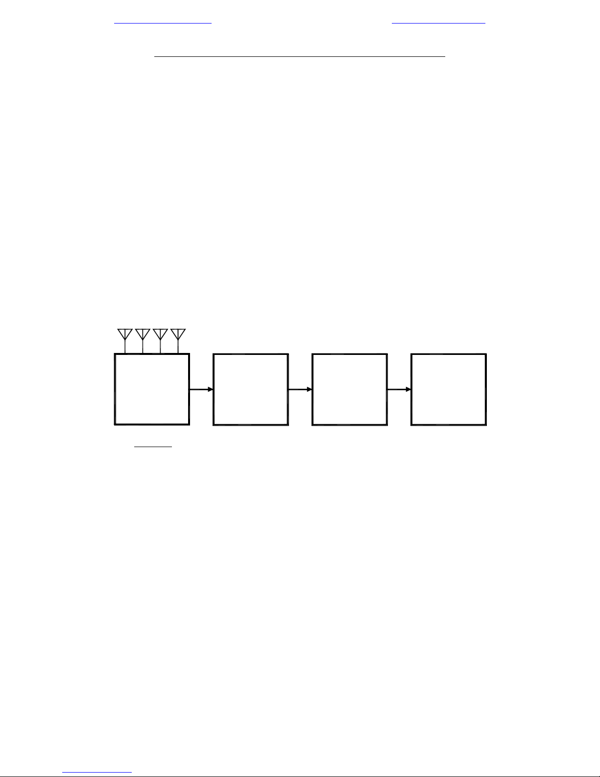
Watson-Watt DF system can be broken down into the following four basic functional blocks:
1. DF Antenna
2. DF Receiver
3. DF Bearing Processor
4. DF Bearing Display
DF ANTENNA DF RECEIVER
Figure 9 - Watson-Watt DF System Simplified Functional Block Diagram
DF BEARING DF BEARING
PROCESSOR DISPLAY
As per Figure 12, the DF antenna receives the incoming wavefront, appropriately processes
the signal and feeds it to the DF receiver. The DF receiver further processes the signal,
demodulates it, and feeds it to the DF bearing processor. The DF bearing processor then
provides additional signal processing and converts the signal into a format suitable for driving
the DF bearing display.
A standard Watson-Watt DF system employs either Adcock or loop DF antennas, with
Adcocks usually preferred because of their superior performance. Actually, the DF antenna
is really an array of three separate but co-located antennas. Referring to a 4-aerial Adcock
configuration, the first of these antennas is the N-S bi-directional array comprising the north
and south aerials. As illustrated in Figure 13 below, the resulting figure-of-eight az imuthal
gain pattern consists of circular lobes with maximum sensitivity to the north and south and
nulls to the east and west. This figure-of-eight gain pattern is obtained by applying the N and
S aerial voltages to a differencing network that vectorially subtracts them (N-S).
The second of these antennas is the E-W bi-directional array comprising the east and west
aerials. Again as illustrated in Figure 13, its azimuthal gain pattern is identical to that of the
N-S bi-directional array, but orthogonally oriented (as a consequence of the fact that the two
arrays are physically at right angles to each other). This pattern is again obtained by applying
23 of 29 - RDF Products - Vancouver Washington USA

mail@rdfproducts.com -- Copyright © 2015 by RDF Products -- www.rdfproducts.com
the E and W aerial voltages to a differencing network that vectorially subtracts them (E-W).
The third of these antennas is the omni-directional sense antenna. In early Adcock designs,
a central sense antenna was implemented using a single aerial physically centered in the
Adcock array. Most (but not all) modern Adcock antennas employ a derived sense antenna
configuration whereby the omni-directional pattern is derived by vectorially summing the
output voltages of all four aerials. This omni-directional sense azimuthal gain pattern is
illustrated in Figure 13. The sense antenna is required to resolve a 180E bearing ambiguity
that would otherwise result. Early Watson-Watt DF systems required three separate but very
carefully matched receivers to process the three DF antenna outputs. Since this was
expensive and it was operationally difficult to maintain the precise gain and phase matching
among the three receivers necessary for good bearing accuracy, an antenna axis tone
encoding (modulation) scheme was developed so that all three DF antenna outputs could be
combined into a single composite signal that could be fed to a single receiver. Essentially, this
is done by amplitude modulating the N-S bi-directional output with one tone and the E-W bidirectional output with another. The receiver then processes this composite signal in the
standard fashion and recovers the two tones (whose respective amplitudes are now
proportional to the two bi-directional antenna outputs) from its AM demodulator. These two
tones are then fed to the DF bearing processor where they are separated and converted into
proportional DC voltages, which in turn drive the bearing display.
Analog bearing displays are typically two-phase devices such as a CRT or magnetically
controlled mechanical pointer. For a CRT display, these two DC voltages drive the CRT X
and Y deflection amplifiers, resulting in a true real-time polar bearing display. For a
mechanical pointer display, these two DC voltages drive the X and Y deflection coils.
Bearings can also be computed in software and then displayed in a variety of different
formats. This is typically accomplished by first converting the X and Y DC voltages to a digital
format using an analog-to-digital converter. The resulting digitized representation of the DC
voltages is then fed to a microprocessor, which in turn computes the bearing in software using
a 4-quadrant arc-tangent algorithm. Once the bearing has been computed, the
microprocessor can then drive one or more of several different bearing displays, including
azimuth rings, numeric displays, or even computer emulations of analog bearing displays.
For a more detailed explanation of the Watson-Watt DF
technique, see RDF Products Web Note WN-002
(“Basics Of The Watson-Watt DF Technique”). WN002 can be downloaded from the RDF Products web
site at www.rdfproducts.com
, and is also included on
the RDF Products publications CD.
Figure 10 - Adcock DF Antenna
Azimuthal Gain Patterns
24 of 29 - RDF Products - Vancouver Washington USA

mail@rdfproducts.com -- Copyright © 2015 by RDF Products -- www.rdfproducts.com
APPENDIX A - INTERFACE CABLE MATING CONNECTOR PIN-OUT
Refer to Figure 14 below for the pin-out of the mating connector for the female microphone
(mobile radio) connector terminating the multi-conductor (antenna control) portion of the
antenna interface cable. This is the “Antenna Control” male chassis connector on the DF
receiver/bearing processor.
Note that while the current “B-series” equipment employs an 8-pin connector for this purpose,
earlier DF processors (e.g., the DFP-1000, DFP-1000A, DFP-1010, DFR-1000, and DFR1000A) employ a 7-pin connector. Figure 14 illustrates both connector styles along with a pinout list.
As can be seen from the illustration, the pin-outs are nearly identical, with the only difference
being how the ground connection is implemented. With the 7-pin version, the connector metal
shell (body) is relied upon to provide the ground connection. With the 8-pin version, the added
8th pin provides the ground connection. The standard microphone connector termination for
the DFA-1325B2 interface cable is the 8-pin version, although users with earlier DF
processors can purchase the RDF Products DCA-087 Cable Adaptor.
Figure 11 - Interface Cable Mating Connector Pin-Outs
The pin functions are explained below:
Pin 1 - X-axis encoding tone from DF receiver/bearing processor (1 volt p-p sinusoid).
Pin 2 - Y-axis encoding tone from DF receiver/bearing processor (1 volt p-p sinusoid).
Pin 3 - Antenna band switch line (Bit-1).
Pin 4 - Antenna band switch line (Bit-2).
Pin 5 - Antenna band switch line (Bit-4).
Pin 6 - 11-16 volt DC power from DF receiver/bearing processor.
Pin 7 - Antenna band switch line (Bit-3).
Pin 8 - Ground (8-pin version only)
Shell - Ground (7-pin version only). The connector shell must be connected to the DF
receiver/bearing processor chassis ground.
Note that setting all four band switch lines low signals the personality module to report the
model and band information. This information is sent as a 300N81 RS-232 data string in TTL
format, and is sent repeatedly as long as all four band switch lines are held low. The string
format is as follows:
DFA-1325B-2, 60-200, 200-1000<CR><LF>
25 of 29 - RDF Products - Vancouver Washington USA

mail@rdfproducts.com -- Copyright © 2015 by RDF Products -- www.rdfproducts.com
APPENDIX B - INTERFACE CABLE EXTENSIONS
Although the supplied captive 8-meter interface cable set should be sufficiently long for most
applications, there may be some applications where a longer cable is necessary (e.g., if the
DFA-1333B1 is to be mounted atop a tall tower, or if the operator’s console cannot be located
close to the DF antenna). Although this can be done, there are certain issues that the user
should keep in mind.
Addressing first the 8-conductor control cable, this cable can be extended out to 100 meters.
This cable should employ #22 AWG wires with a weather-proof jacket. If the cable will be in
direct sunlight, the jacket should have an appropriate UV rating. Alpha Wire & Cable P/N
1178C works well for this purpose (available from Mouser Electronics, Inc.; P/N 602-1178C500 (the last three/four digits specify the cable length in feet, with standard lengths of
100/500/1000 feet).
Mating connectors are available to match the 8-pin mobile radio plug connected to the end of
the 8-meter antenna control cable. Keep in mind, however, that these mobile radio
connectors are not waterproof, so it will be necessary to seal the junction to prevent water
intrusion if this junction is outdoors.
Alternatively, the 8-pin mobile radio plug can be cut off and the end directly spliced onto the
extension cable. Again, this junction must be appropriately sealed against water intrusion.
For a long cable run, it is possible that there may be excessive voltage drop through the +13.8
VDC line. It is important that the user verify that the DC supply voltage presented to the DFA1333B1 be no less than 11.0 VDC under full load (i.e., with the antenna connected) to
guarantee that the internal voltage regulator will not drop out of regulation. If the voltage
presented to the DFA-1333B1 is less than 11.0 VDC, the most expedient means to correct this
is to “goose-up” the head-end DC power supply voltage (connected to the DFP-1000B/DFP1010B DF processor) slightly.
Many DC power supplies have internal adjustments allowing the output voltage to be raised
or lowered slightly. If this is the case, the output voltage can often be raised to offset the
antenna control cable wire voltage drop. Since the DFP-1000B/DFP-1010B can accept up
to +16 VDC, there is considerable latitude to raise the supply voltage as required to offset this
voltage drop. (Be certain, however, that this voltage does not exceed the host receiver input
DC voltage rating if this host receiver is powered from the same supply.)
For a fuller discussion of this DC voltage drop issue, see Section IV (“Extended Interface
Cable Lengths”) of the “DFA-Series Mobile Adcock Radio Direction Finding Antennas”
Operator’s Manual. This manual can be downloaded from the RDF Products website.
With regard to the RF output cable, an extension can be added using an appropriate coaxial
cable adaptor as required. If this junction is outdoors, it will have to be weather-sealed if the
junction is not inherently weather-proof.
The two major concerns with respect to the selection of a suitable RF extension cable are
cable loss and cable shielding. Since coaxial cables have significant loss in the 60-1000 MHz
range covered by the DFA-1325B2, a premium low-loss cable must be used for a long
26 of 29 - RDF Products - Vancouver Washington USA

mail@rdfproducts.com -- Copyright © 2015 by RDF Products -- www.rdfproducts.com
extension. As a point of reference, matched cable loss per hundred feet for RG-223 (the RF
output cable supplied with the DFA-1333B1 is approximately 3.4 dB at 60 MHz and 17.6 dB
at 1000 MHz (for 50 feet these dB loss figures would be halved). Since losses of this
magnitude can noticeably degrade system sensitivity (especially at the higher frequencies),
it is better to use a premium low-loss cable such as RG-214 (with corresponding 100 foot
cable losses of 1.7 dB at 60 MHz and 8.4 dB at 1000 MHz).
If extension cable losses cannot be kept within reasonable bounds, a cable line amplifier can
be employed. Since this amplifier is likely to be exposed to a large number of strong signals
over a wide frequency spectrum, it is important that it be a premium device having very wide
dynamic range and good strong signal handling capability so as to minimize the generation
of intermodulation products that can interfere with desired signals.
Cable shielding is also very important. If inexpensive coaxial cable is used, it is likely to suffer
from signal pickup that will degrade DF antenna performance. To explain, it is very important
that nearly all signal pickup be from the DF antenna itself rather than from the coaxial feedline.
If significant feedline pickup occurs, bearing errors and reduced sensitivity are the likely result.
This shielding issue becomes more of a problem at higher frequencies and for longer cable
runs.
It is therefore very important that double-shielded coaxial cables (i.e., RG-223 and RG-214)
be used for cable extensions. Always avoid less expensive substitutes such as RG-58 and
RG-213 - these cables do not have adequate shielding.
27 of 29 - RDF Products - Vancouver Washington USA

mail@rdfproducts.com -- Copyright © 2015 by RDF Products -- www.rdfproducts.com
APPENDIX C - MORE ON LIGHTNING PROTECTION
Addressing DF system lightning safety issues more fully, we advise users to prioritize these
issues in the following order:
1. First and foremost, protection of personnel must always be the highest priority.
2. The next most important issue is the protection of all equipment at the operating console
including the building housing this equipment.
3. The DF antenna and its associated cables are the final priority.
Issues #1 and #2 are best addressed using a special lightning protection interface panel for
the DF antenna cables. This panel includes lightning arresters that are intended to protect
personnel and equipment at the operator console. These panels are specialized products that
can be obtained from various sources. One of these sources is PolyPhaser
(www.smithspower.com/brands/polyphaser/). PolyPhaser also posts relevant literature on this
website that is well worth the time to read.
Unfortunately, the DF antenna itself is very hard to protect from a lightning strike. Although
one might think that a tall grounded lightning rod extending vertically through the center of the
chassis would serve this purpose, this is not the case for the following two reasons.
First, keep in mind that any conductive object in the vicinity of the DF antenna is an
unintended parasitic re-radiator. In effect then, this conductive object becomes part of the DF
antenna. In the general case, this undesired parasitic re-radiation results in pattern distortions
that can cause serious performance degradation.
For a fuller discussion of this issue, see our 1999 Application Note AN-005 (“An Introduction
to Dipole Adcock Fixed-Site DF Antennas”). In particular see the discussion in Section V-D
(“Dipole Adcock Performance Degradation Caused by the Vertical Support Mast”) beginning
on page 13. This discussion details the adverse effects of the central vertical support mast
(which in effect is what a lightning rod would be) on DF antenna gain patterns. The paper
goes on to discuss how this issue is resolved in RDF Products dipole Adcock DF antennas
by means of a special “iso-mast” (a special mast isolation technique employing ferrites).
Replacing this iso-mast with a lightning rod would reverse all of the careful and timeconsuming
engineering effort that was invested in its development and would undo one of the premier
features of RDF Products dipole Adcock DF antennas that distinguish them from less capable
competing designs.
The second issue is that even if such a lightning rod could be installed with no adverse
performance repercussions, it would almost certainly be ineffective in protecting the DF
antenna. To explain, the discharge voltage of a lightning strike on the lightning rod would
typically be in excess of 1,000,000 volts with a resulting current pulse peaking at over 10,000
amperes. In addition to likely structural damage, this massive current pulse would result in
a localized electro-magnetic pulse (EMP) that would almost certainly destroy any
semiconductors inside the DF antenna. (Unlike passive FM broadcast, TV, and shortwave
receiving antennas, DF antennas contain active electronics.)
28 of 29 - RDF Products - Vancouver Washington USA

mail@rdfproducts.com -- Copyright © 2015 by RDF Products -- www.rdfproducts.com
With these issues in mind, we believe that the best course of action is to invest whatever is
necessary to protect personnel, operating equipment, and the building housing this equipment
from a lightning strike as discussed above, but to recognize that there is no practical or
reliable way to protect an antenna containing active electronics from this same event. <>
29 of 29 - RDF Products - Vancouver Washington USA
 Loading...