

Page 1
Programming the panel for radio
communication
The internal radio transmitter is able to report the
following telemetry conditions:
Step 1
Programme the “T” parameter in the “MS 1
Protocol” screen to “T=2” - RDC radio transmitter is
installed.
Step 2
In the MS 1 & 2 “Options” in the “Communication”
menu, all the parameters are disabled (‘-‘) by factory
default (including after panel initializing). Enable
ONLY the required telemetries with careful
reference to the note below.
NB: ONLY ENABLE CRITICAL
TELEMETRIES. Indiscriminate activation
of non-critical telemetries (including
Open/Close) for radio communication can
lead to network congestion and may
result in critical signals being lost. Panel
specific telemeteries such as keypad
failure and restore, phone-line failure and
restore, siren failure and restore etc.
should NEVER be activated.
! Up to 4 partitions are supported / reported
! Up to 31 zones are reported
(zone 32 reserved for universal or unknown zone)
! Up to 15 users / key holders are reported
(user 16 reserved for universal or unknown user)
! Only battery low and AC fail restorals are reported
! All standard RDC type telemetries are reported
TX-7serial Pima - Installation Instructions
Transmitter standby - battery voltage correct
Transmitting
Mains fail
Battery voltage too low for normal operation
Low battery, but still able to operate
Battery over voltage
Incorrectly programmed
LED indicates transmitter conditions:
ADI Support
0800 234 468
RDC 24hr Standby
082 444 7176
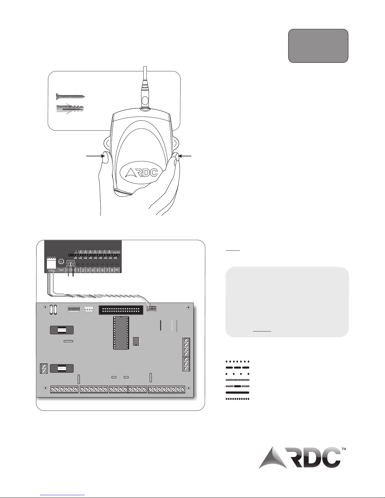
Squeeze the
lid firmly on
both sides just
below the
mounting holes
to remove the lid
Recommended mounting
screws and plugs
M4.5 x 30 mm
countersunk head
self tapping
6 x 35 mm
Mounting screws and
plugs not included
www.radiodata.co.za
Connect the transmitter
to the panel by connecting
the 4-way connector to JP4
on the PIMA panel.
DC power - connect directly
to system battery
TRANSMIT KEYPAD
SERIAL
JP4
JP2
JP1
Rev 115 1211
Page 2
Connecting a Black Max antenna to
extend the range (NOT SUPPLIED)
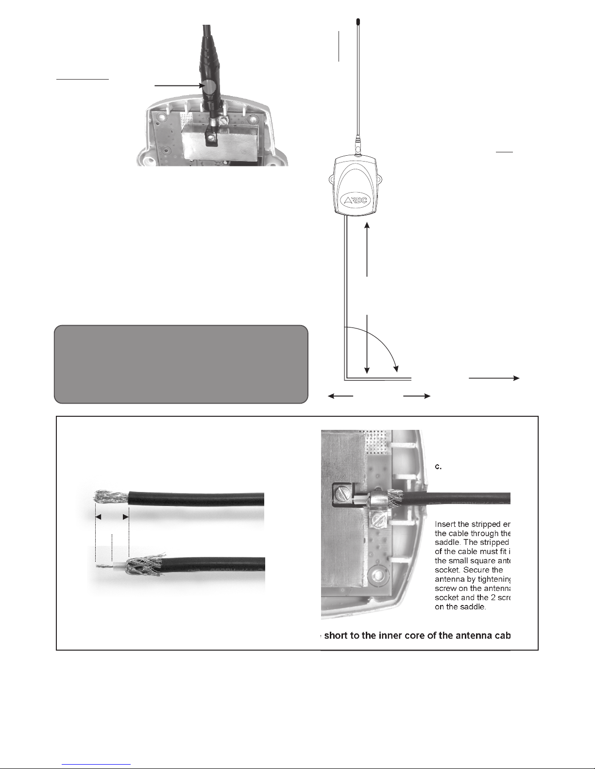
Strip off 12mm of the outer insulation taking care not to
damage the braiding.
Fray and pull back the braiding and strip off 6mm of
the inner white insulation leaving 6mm of the inner
wire exposed.
12mm
6mm 6mm
12 Volt power connection
During transmission the transmitter
draws up to 1.8 Amps from the battery
at 12V. Using thin wire between the
battery and the transmitter will restrict
the RF power on transmission and
prevent it from working reliably.
Always use a minimum of 0.5stranded wire for the 12- Volt input.
Four-core wire is definitely NOT
recommended.
The maximum recommended wire
length is 7m. If the transmitter is to be
mounted more than 7m from the
control panel, a second battery may
be mounted near the transmitter.
NB: Remember, for maximum
performance, always use the thickest
possible wire, and keep it as short as
possible.
The 12V DC wires should be run
straight down from the transmitter for
360mm before being turned 90º either
left or right, and run towards the
control panel.
Whip antenna
To install the antenna, slide it through the saddle and firmly into the
square connector next to the screw. Tighten the square connector and
saddle screws.
NOTE: The whip antenna is cut to the correct length. Cutting or
lengthening the antenna will negatively affect the transmitters’
performance.
The antenna must not be mounted less than 2m from any large metal
object.
!
The transmitter generates a very strong RF field around the
antenna. This RF field can affect other electronic equipment, such
as computers, television sets, music systems, and alarm
equipment, especially passives.
!
When mounting an antenna against a wall, always check for metal
objects or other electronic equipment on the other side of the wall.
,
360mm
Left or right
To the battery
The antenna MUST
be mounted vertically!
90º
Insert the stripped end of
the cable through the
saddle. The stripped end
of the cable must fit into
the small square antenna
socket. Secure the
antenna by tightening the
screw on the antenna
socket and the 2 screws
on the saddle.
a.
b.
c.
NOTE: Ensure that none of the strands of braiding wire short to the inner core of the antenna cable!
directors, employees and agents of whatsoever nature, in any of or damage to any property, including any pure economic
Disclaimer
amount whatsoever, arising from any failure in or malfunction of loss) arising from any failure of or malfunction of a security
“RDC records that it merely supplies the products to the
a security system containing the products, or from the use of system containing the products installed by or on behalf of the
customer and that the customer has the sole responsibility to
the products, and whether arising from the negligent act or customer, or from the use of the products in any such system
install the products and/or to incorporate the products in
omission, gross or otherwise of RDC, its directors, employees whether or not arising from the negligent act or omission, gross
security systems. RDC does not take any responsibility for the
or agents. or otherwise of RDC, its directors, employees and agents.”
installation of the products or for ensuring that any installation
The customer indemnifies and holds harmless RDC and its
complies with SAIDSA Specification for Intruder Alarm
directors, employees and agents of whatsoever nature in
Systems for Domestic, Commercial, Retail and Industrial
respect of any and all loss, damage, costs, expenses or claims
Installations.
which have been incurred by or brought against them by any
The customer shall also have no claims against RDC, its
third party (whether for the death or injury of any person or loss
Copyright © 2011
Radio Data Communications (PTY) Ltd.
PLEASE NOTE: The transmitter should never be triggered
without a suitable antenna being connected. If the transmitter is
used with the built in whip antenna, ensure that it is properly
connected, fully extended and away from any metal obstructions.
Triggering the unit without an antenna or a folded/ bent antenna
may cause permanent damage to the transmitter and/or
unpredictable and erratic behavior.
The round indentation on
the antenna must always
face upwards. The lid
will not fit if the antenna
is not oriented correctly.
 Loading...