

Page 1
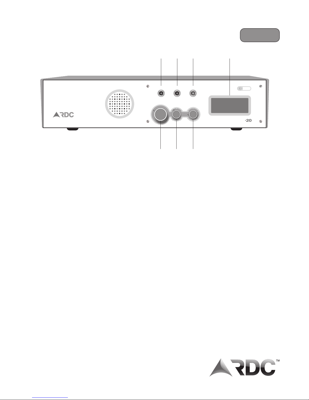
A POWER LED indicates 12v dc to the unit is present
B MONITOR LED flashing once per second indicates normal operation
flashing twice per second indicates AC fail
C AC LED on indicates 220V ac to charger is on
D RECEIVER SELECT select and “listen in” on radio signals etc. on the various frequencies (max 4)
turning off the switch will turn off the display back-light (power save mode)
E VOLUME CONTROL increase or decrease the audio volume
switch is off for normal operation
F SQUELCH CONTROL adjusts the required squelch threshold
turn off for normal operation
G LCD DISPLAY displays the last 4 events - scrolls up
System Defaults
SELF TEST INTERVALS 60 minutes
AC FAIL DELAY 15 minutes, thereafter every 30 minutes
TRANSMISSION TIME 118 mS
CURRENT DRAW back-light off - receive mode 1 receiver 200mA
4 receivers 480mA
back-light on - receive mode 1 receiver 290mA
4 receivers 570mA
- transmit mode 1.5 A
Reporter D20 - Information & installation instructions
24hr Standby
082 444 7176
Squelch
Receiver Select
off
1
2
3
4
Volume
ACPower Monitor
IC
S
Approved
RX-301/93
A
B
C
D E
F
G
Rev 16 0911
D
TM
24HR SUPPORT LINE +27 82 444 7176
Page 2
ANTENNA LINK
0001
A B C
D E F G H
1
2
4
3
Serial No.
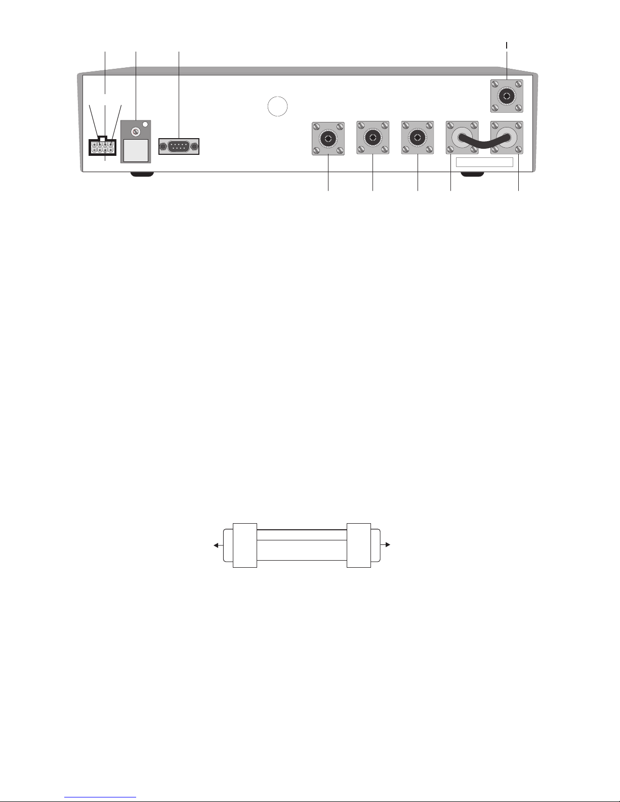
A MOLEX CONNECTOR 1 Red - 12V DC (12v battery)
2 Black - 0V DC (12v battery)
3 White - AC fail monitor - connects to AC fail output of a power supply
When output is 12V - unit detects AC present
When output is 0V - unit detects AC fail
4 Green - Earth
If unit is being powered by a battery and solar panel, the white wire should be
connected to +12V DC
B PERSONALITY MODULE can only be programmed by RDC
NB. Each personality module is specifically programmed for a specific repeater or
base station unit and a specific location. Interchanging or replacing the
incorrect personality modules will cause serious network problems.
C COMPUTER RS 232 CABLE RS 232 Protocol
Baud Rate 9600
Data Bits 8
Flow control off
Parity none
Stop Bits 1
RS 232 cable
RS 232 cable to computer not to exceed 10 meters
D RECEIVER 4 ANTENNA INPUT (when in use)
E RECEIVER 3 ANTENNA INPUT (when in use)
F RECEIVER 2 ANTENNA INPUT (when in use)
G&H CONNECT TOGETHER WITH JUMPER CABLE (provided)
I RECEIVER 1 AND TRANSMITTER ANTENNA NB. Must be connected directly to antenna and not to a multi coupler.
DB9
female
DB9
female
to D20 unit
to computer
3
2
5
2
3
5
Page 3
Diagnosis and Solution
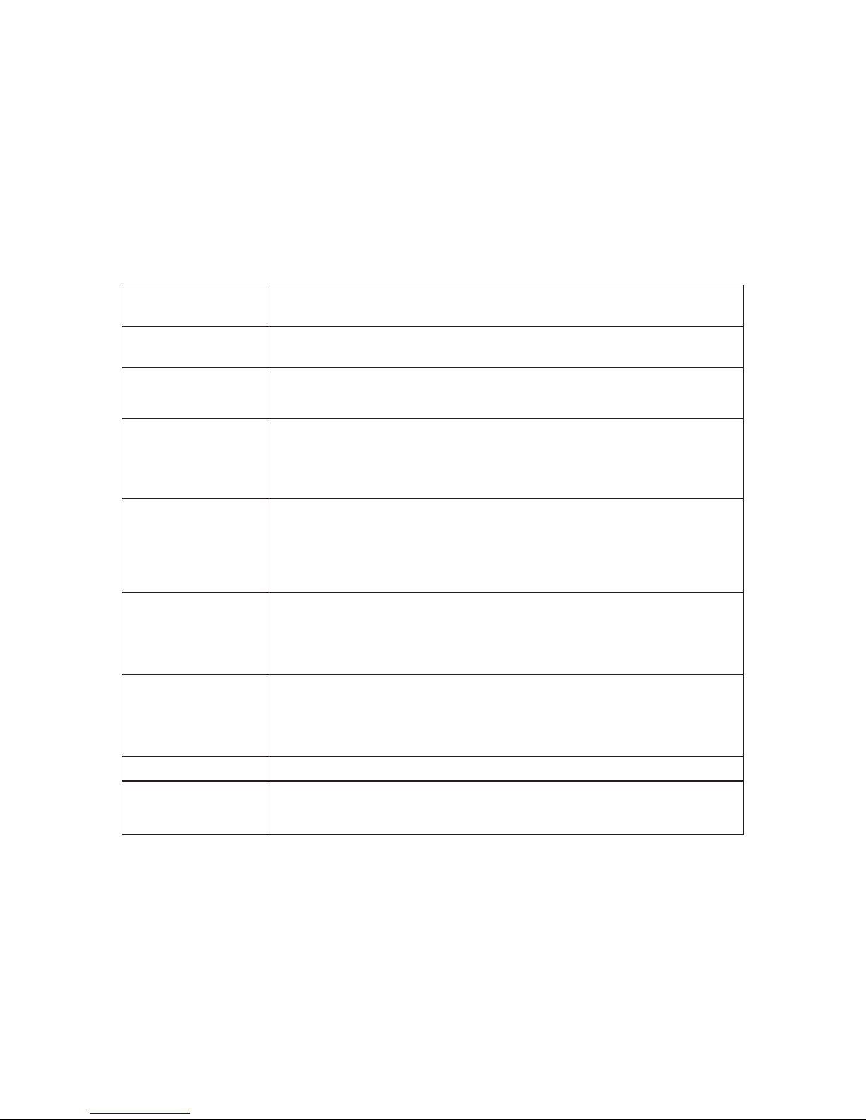
Check DC cable is firmly connected to back of unit / Cable plugged in / Batt connected
to charger / Check battery voltage
Selection switch is in OFF position. Turn selection switch to position 1. After test is
complete, return switch to OFF position to conserve battery power during mains
failures. In case of a base station, the back light may be left on.
Trigger a test transmitter with it's antenna removed near the D20 and note if code is
displayed. If code is displayed D20 is operating correctly.
Ensure that antenna loop on D20 has been correctly installed.
Check correct antenna connection.
Check antenna and antenna cable condition using SWR meter.
Check RS232 cable and connection between base and computer.
Run hyper-terminal on your computer, trigger a test transmitter and confirm that the
transmitter code is displayed on the hyper-terminal window. If code appears on is
displayed then communication exists between D20 base and computer.
Ensure control room software has been set up to read the RS232 string from the base
station. If not consult software provider.
Poor or no RF path between repeater and base.Ensure that antenna loop on D20 has
been correctly installed.
Check correct antenna connection.
Check antenna and antenna cable condition using SWR meter.
Poor or no RF path between originating repeater and destination repeater.
Ensure that antenna loop on D20 has been correctly installed.
Check correct antenna connection.
Check antenna and antenna cable condition using SWR meter.
An additional repeater may be necessary.
Select appropriate channel on select sw.
Check proper connection of antenna link at back of base. Check antenna (with SWR
meter).
Problem
Unit is dead
No back light on display
Radio codes are not
displayed on D20
screen
Codes displayed on
D20 Base but not on
computer screen.
Radio codes appear on
repeater display but not
on base display
(for repeaters close
to the base)
Radio codes appear on
repeater display but not
on base display (for
repeaters far from the
base)
No sound
Not receiving radio
signals @ base from
radios in the field
 Loading...