


SETUP
This setup manual contains a short instruction required
for installing, wiring, commissioning and operating the
inverters. For further instructions on installing or
operating, please refer to the detailed user manual,
which you can access via www.rct-power.com.
RCT Power GmbH reserves the right to make changes
to specifications or documents without prior notice.
RCT Power GmbH shall not be responsible for any
damages resulting from use of this document.
This document does not replace any applicable laws,
regulations, standards or codes.
Warranty conditions come enclosed with the device.
No warranties can be derived from this document.
Intended Product Usage
To prevent personal injury or property
damage, the inverter must only be installed,
wired, connected, commissioned, maintained
and serviced by qualified personnel:
•
Trained in installing electrical devices.
•
Familiar with all applicable laws, regulations,
standards and codes for electrical devices.
•
Familiar with safety requirements and safety-related
guidelines for electrical devices.
•
Familiar with work protection laws and regulations.
•
Using the appropriate personal protective equipment.
Power Storage 4.0, 5.0 and 6.0 are stationary 3-phase
string inverters with integrated battery charger. They
convert direct current (DC) supplied by the PV array and
the battery into alternating current (AC), which can be fed
into the electricity grid.
They are not designed for any other application or
connection to other devices.
Any use that differs from or goes beyond the intended
usage is considered misuse. RCT Power GmbH shall not
be liable for any damage resulting from misuse.
Any misuse will terminate warranty, guarantee and
general liability of the manufacturer.
EN
Symbols
Level of risk
Explanation
high
medium
low
Immediate
danger of death
or serious injury
Immediate
danger of minor
or moderate
injury
Danger of
equipment or
property damage
Installation
Power Storage 4.0 / 5.0 / 6.0

In 9 Steps to the installed system
Assembly and mounting.
(Section 2, p.3).
Electrical connection of the devices.
(PV, grid, battery section 3, p.4-5 / Communication section 4, p.7 /
Power Switch, Power Sensor section 5&6&6.1, p.8-10).
Inverter switch on (switch on fuses).
(Section 7.1, p.11).
Access to the inverter via APP.
(Steps 1 to 5 in the setup section 7.2, p.11-12).
Configure the inverter, select the land and norm.
(Steps 6 to 9 in the setup section 7.3, p13).
Power Sensor configuration (PV power must be >250W, so the sensor is correctly
detected and tuned, flash).
(Step 10 in the setup section 7.3, p.13).
Configure the Power Switch, if available.
(See Manual, Power Switch).
Configure the battery.
(Steps 11 to 14 in the setup section 7.3, p.13-14).
The configuration of the battery is now complete.
After the inverter has checked the specifications, it starts charging the battery.
2

[1] Scope of Delivery
Fig.1
Look over
user manual.
Wait 10 minutes after
disconnection before
touching inner parts.
Hot surface
Electrical device:
grounding necessary
[2] Inverter Mounting
Item
Description
A
Setup manual
B
PV input- and battery connectors
(Weidmüller PV-Stick)
C
Wall bracket for mounting inverter
D
Inverter
a
LCD display for information on inverter operation
b
DC switch for emergency shutdown of inverter
c
DC PV plugs
d
Cable entries for communication ports
e
Cable entry for AC cable
f
Screw hole for additional protective grounding
g
Name plate with technical data, serial number,
symbols:
h
DC battery plugs
i
Cable entries for RJ45 connectors, Battery,
Power Sensors and Power Switch
Item
Description
A
Select non-flammable, firm wall. Room may not
contain highly flammable goods, liquids or gas.
B
Protect from snow, rain, direct sunlight and dust.
Observe allowed ambient temperature (-25 … 60°C).
Maximum degree of pollution PD2.
C
Mount in upright position. Ensure enough space for
easy access. Make sure wall supports inverter
weight.
D
Minimum clearance: half of inverter width at both
sides and half of height at top and bottom.
E
Do not place inverter in closed cabinet.
Step
Description
1
Attach wall bracket firmly to wall with 3 to
6 screws (ø 6 to 8 mm), matching wall
plugs and washers (outer ø min. 18 mm).
Material not included in delivery.
2
Take out locking screw of inverter
housing. Hook inverter onto wall bracket
and fix locking screw back.
3

[3] Electrical Connection
[3.1] Overview Connection Parts
Fig. 2
[3.2] AC Connection
Risk of death or injury due to electric shock!
While the inverter is connected to grid (AC
voltage source), to PV array which is exposed to
sunlight (DC voltage source) or to the battery
(DC voltage source), high voltage is present in
cables and inner parts of inverter.
•
Important: All voltage sources (DC / PV-generator,
DC / battery and AC / utility grid) must be disabled
before any electrical work.
To disable PV-generator DC voltage connection turn DC
switch to 0-position and wait 10 minutes before
continuing.
To disable AC voltage connection turn off AC switch,
main breaker or fuse. Make sure, other persons don’t
switch back.
Do not enable voltage connections until work is finished.
•
To disable DC battery voltage connection both voltage
sources (DC / PV-generator and AC / utility grid)
must be disabled.
•
During AC connection: Do not exchange L, N and PE
wires!
•
Make sure other persons keep away during electrical
work.
Risk of death or injury due to electric
arc!
Disconnecting DC plugs under load can
cause electric arcs.
Risk of damage due to improper
installation and operation or misuse.
•
Contact local utility company or grid operator
before connecting inverter to grid.
•
Provide for an AC disconnection device
(typical miniature circuit breaker 3 pole 6kA,
B-characteristic 16A).
•
If required in country or installation, install a
residual-current device (RCD), or residualcurrent circuit breaker (RCCB).
•
Inverter contains no owner serviceable parts.
Contact local authorized personnel for service.
•
Do not remove name plate.
•
Only RCT Power certified batteries complying
with the demands of the certain region are
allowed to be used.
Item
Description
A
AC terminal block for L1, L2, L3, N and PE
phases.
B
Clamps for parallel DC mode.
C
Communication board.
D
RJ45 Connectors for Battery communication
via CAN, Power Sensor and Power Switch.
Step
Description
1
Remove cover of inverter. Locate AC
terminal block (Fig. 2, A).
2
Feed cable through AC entry (Fig. 1, e).
Push down clamps to insert L1, L2, L3, N
and PE.
3
Tighten swivel nut of cable entry.
4

[3.3] DC Connection
[3.4] DC Parallel Mode
Material not included in delivery.
This section applies only, if several Strings with an
equal amount of modules are to be connected in
parallel and the maximum input current per input
therefore exceeds 12A.
Step
Description
1
Remove cover of inverter. Locate clamps
for parallel DC mode (Fig. 2, C).
2
Connect clamps X101 and X104.
To prevent personal injury or property
damage, make sure that there is no PVDC connector plugged and DC-switch is
“0” in during this installation.
[3.5] DC Battery Connection
Make sure DC switch is “0”, the battery ON/OFF switch set to “0” and AC switch, main breaker or fuse is “OFF”.
Plug corresponding plus and minus poles into battery plugs of inverter.
(The connection cable from the inverter to the battery is not included).
Step
Description
1
Do not turn plug parts before inserting the
cable.
Select correct plugs for polarity of PV and
battery strings.
2
Push cable into plugs straight until the spring
clamp locks.
3
Turn lower part of plug shut.
4
Make sure DC switch is “0”. Plug
corresponding plus and minus poles into
adjacent PV plugs of inverter (Fig. 1, c).
DC cable -
DC cable +
5

[3.6] Second Protective Inverter Grounding
Material not included in delivery.
If required in the country of installation, attach a second protective earth connection to the Power Storage Inverter
housing.
6

[4] I/O-Board Communication Connection
Fig.3
Communication Ports
[4.1] Connection of Communication Ports
[4.2] Wiring of Communication Ports
Item
Description
1
X102: serial RS485 interface.
2
X100: Multifunctional Relay, max. 24 V, 1
A.
3
X101, Power management: 4 digital inputs
for potential free relay contacts.
4
X103: Digital in/out, max. Input 24 V,
max. output 5 V, 10 mA.
Step Description
1
Open cable entry (Fig. 1, d) and feed cables.
2
Select correct port (see next section), press down spring clamp, insert cables and release.
7

[5] RJ45 Connectors for Power Battery, Power Sensor and Power Switch communication
The inverter communicates with the battery via the CAN-Bus. If inverter is delivered with optional Power Sensor
and Power Switch please refer to user manual of these items for further detailed commissioning information.
Fig. 4
RJ45 – Communication Ports
[5.1] Connection of RJ45 – Communication Ports
[5.2] Wiring of RJ45 – Communication Ports
Standard communication with Power Battery
Additional Power Switch communication
Additional Power Sensor communication
Additional Power Switch and Power Sensor
communication
Item
Description
A
X403: Battery communication connector.
B
X403: Not used.
C
X403: Power Sensor communication
connector.
D
X403: Power Switch communication
connector.
Step Description
1
Open cable entry (Fig. 1, i) and feed cables.
2
Select correct port (see Fig. 4 and next section), insert cables in RJ45 connectors.
8

[6] Connection - Power Switch
Step
Description
1
Switch off the system (see section 8).
2
Place the Power Switch in the service entrance box or near.
3
Connect the Power Sensor and the Power Switch via patch cable at the
Power Storage on the communication connector X403.
4
For further configurations please refer to user manual.
This section applies only when using the RCT Power Switch in combination with a battery
system.
9
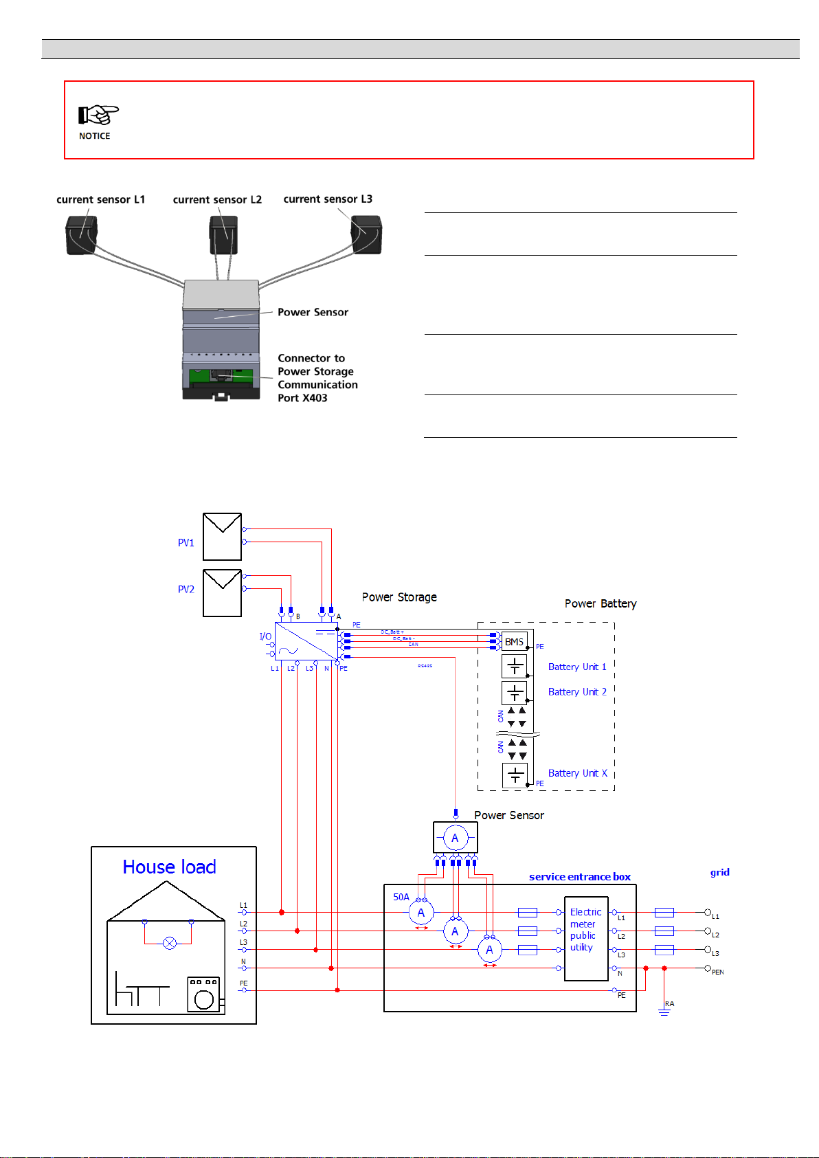
[6.1] Connection - Power Sensor
Step
Description
1
Place the Power Sensor in the service
entrance box.
2
Click the three current sensors around the
L1, L2 and L3 wires in the service entrance
box. (The order and direction of installation
is not important).
3
Connect the Power Sensor to the Current
Sensor communication connector X403 CS
at the Power Storage via patch cable.
4
For further configurations please refer to
user manual.
The Power Storage system functionality depends on energy consumption measurement.
This section applies only to Power Storage Inverters, which are delivered with Power
Sensor.
10

[7] Commissioning
Ensure proper mechanical an electrical installation before commissioning the solar inverter.
Check the cables to ensure, that they are in sound condition.
Always disconnect the mains connection first by switching off the corresponding mains fuse and
before disconnecting the solar generator side by opening the DC load break switch.
The DC-connectors on the solar generator side must not be disconnected under load. First turn the DC
load break switch to position 0.
[7.1] Inverter switch on
Step
Description
1
Establish grid connection via the external circuit breaker.
2
Switch on the solar generator voltage by closing the DC load break switch
(position 1). The solar inverter starts operating, when the input voltage
level and power is adequate.
Display will switch on and show norm „Factory defaults“.
[7.2] Access to the inverter
The Solar Inverter is equipped with an internal Wi-Fi unit. To set up Solar inverter you need to
access via Wi-Fi due to the suitable Android APP.
The Android APP is the central user interface for commissioning.
It ensures easy data collection and troubleshooting.
Obtaining Android App: Go to Google Play Store, search for “RCT Power App”, and install.
Step
Description
1
Activate Wi-Fi on your smartphone (or tablet
computer).
2
Connect with SSID identical with the name of the
Power Inverter on inverter display via Wi-Fi.
(e.g. PS 6.0 8HNE).
If the Inverter is already in a network via
Wi-Fi, connect to the network.
11

2a
If you connect the first time with a device to the
inverter you need a password.
The password corresponds to the serial number of
your device (see display or name plate).
3
Start “RCT Power APP”.
4
Switch to tab “Network” and press “Scan”.
4a
Activate “10.10.100.254“ (or if you have renamed
the device choose this) by choosing radio button.
5
If the connection is made with an inverter, the
name is displayed on the head and the icon is
edged.
Only an example!
12
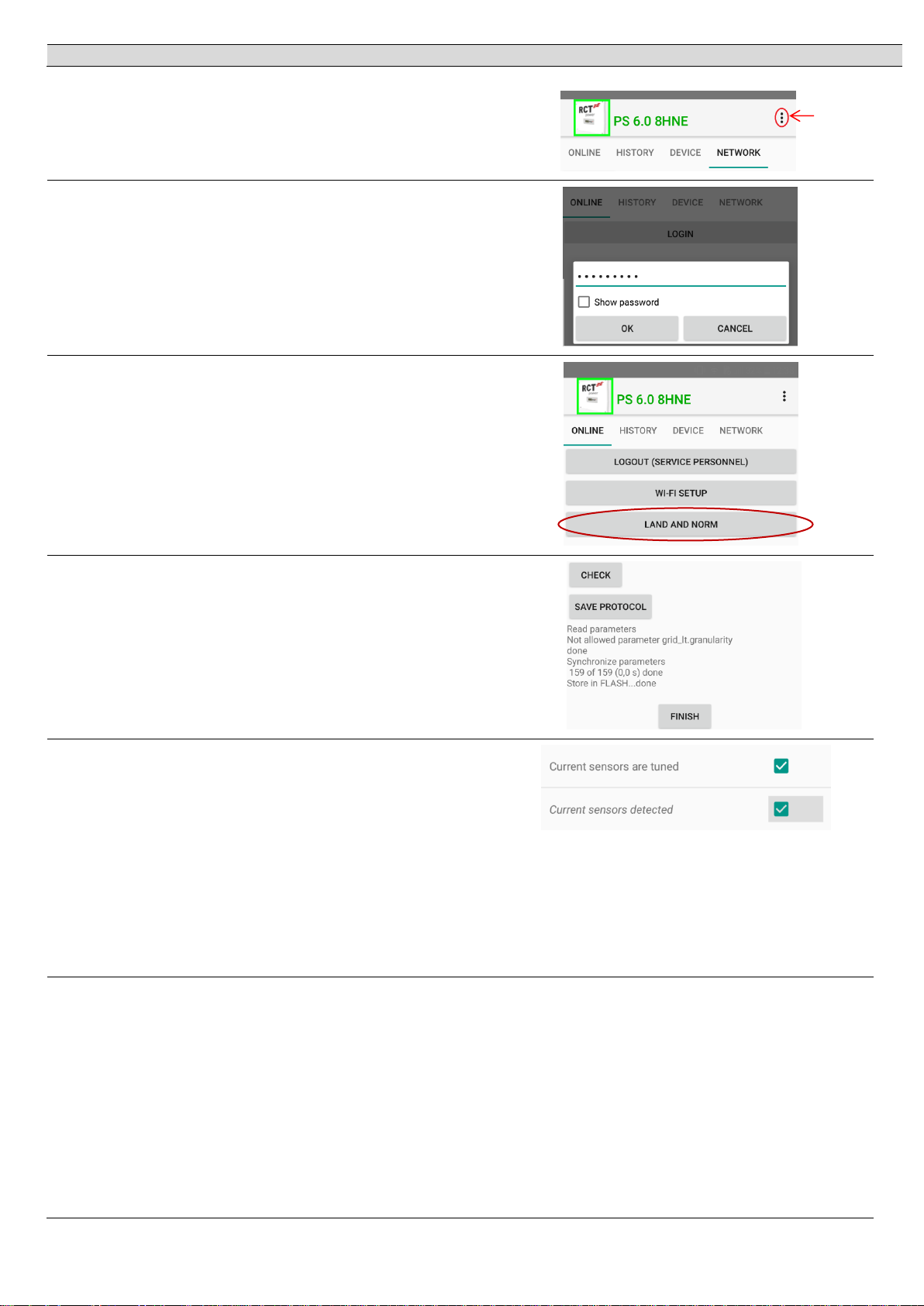
[7.3] Battery and inverter configure
6
Press “menu” and choose “Setup”.
7
Enter setup procedure by “Login”
(password: “installer”).
8
Choose “Land and Norm”, select appropriate
norm and “apply”.
9
Wait during parameters are synchronizing and
stored. When finished press “Finish”.
After the inverter has checked the specifications,
it begins to feed into the grid.
10
The Power Sensor will be detected and tuned,
automatically by an Inverter power of 200 W.
Continue with Device Settings Device
settings (scroll down) Power Sensor tuning
(scroll down)
If current sensors are tuned and detected press
“FLASH” to store settings permanent, finish!
For further configurations please refer to user
manual.
11
Go to “Device” and click “Settings” press “Battery”
and choose “Battery type”.
menu
13

12
Choose “Li-Ion RCT Power” or your appropriate
battery type.
13
Press “Flash” to finish the battery setup and
press “return“ to get on start page.
14
Switch the battery on by setting the battery
ON/OFF switch to “1”.
15
After the inverter has checked the specifications,
it starts calibrating the battery.
The battery is charged to 100%, which can take
several hours.
(When calibrating, power may be used out from
the grid to speed up the process if the power is
insufficient)
When calibration is complete, the system
automatically switches to compensation mode.
[8] How to switch off the system
Step
Description
1
Locate DC switch (Fig. 1, b) and turn to “0” position and switch off the battery with the ON/OFF switch to “0”.
2
Locate and switch off circuit breaker, main breaker or fuse for disconnecting inverter from utility grid.
3
Wait 10 minutes until capacitors have discharged.
4
Locate DC / PV connectors (Fig. 1, c) and DC / battery connectors (Fig. 1, h). Press latches of male plug
together to unlock and pull off DC plugs.
Note: For further information on installation and operation, please refer to the detailed user manual, which
can be obtained from our website www.rct-power.com .
14

[9] Technical Data
Power Storage 4.0 5.0 6.0
Order Number IHP040N1AE0 IHP050N1AE0 IHP060N1AE0
DC-INPUT
Max. recommended DC power 5000 W 6250 W 7500 W
Rated DC power 4200 W 5250 W 6300 W
MPPT 2 (paralleling possible)
Input per MPPT 1
Maximum DC current per MPPT 12 A ( 24 A in parallel mode)
Rated DC voltage 700 V
DC start up voltage / power 150 V / 25 W
DC voltage range 140 V ... 1000 V
MPP voltage range 200 V ... 800 V 220 V ... 800 V 265 V ... 800 V
Maximum voltage DC 1000 V
Connector type
Weidmüller PV-Stick (MC4 compatible)
BATTERY-INPUT
DC voltage range 150 V … 600 V
Maximum charge / discharge current 20 A / 20 A
Maximum charge / discharge power 6000 W / 4000 W 6000 W / 5000 W 6000 W / 6000 W
Connector type Weidmüller PV-Stick (MC4 compatible)
AC-OUTPUT
Rated AC output power 4000 W 5000 W 6000 W
Maximum active power 4000 W 5000 W 6000 W
Maximum apparent power 6300 VA 6300 VA 6300 VA
Nominal AC current per phase 5,8 A 7,3 A 8,7 A
Maximum AC current per phase 9,1 A 9.1 A 9.1 A
Rated frequency 50 Hz / 60 Hz
Frequency range 45 Hz ... 65 Hz
Max. switch-on current 13 A, 0,1ms
Max. fault current (RMS) 285 mA
Rated AC voltage 230V / 400 V (L1, L2, L3, N, PE)
AC voltage range 180V ... 270V
Total harmonic distortion (THD) < 2% at rated power
Reactive power factor (cos phi) 1 (adjustable range 0,8 cap….0,8 ind )
Anti-islanding operation Yes
Earth fault protection RCD
DC-current injection < 0,5% In
Required phases, grid connections 3 (L1, L2, L3, N, PE)
Number of feed-in phases 3
Grid voltage monitoring 3-phase
Type of AC connection Spring clamps
PERFORMANCE
Stand-by consumption < 4.0 W
Maximum efficiency (PV – Grid) 98,16%
European efficiency (PV – Grid) 97,6% 97,7% 97,9%
Maximum efficiency (PV – Battery – Grid) 95,9%
Topology Transformerless
15

OTHER
RCT Power GmbH
Line Eid Str. 1
78467 Konstanz, Deutschland
Tel.: +49 (0)7531 996 77-0
Mail: info[at]rct-power.com
Internet: www.rct-power.com
05/2017
PV – DC-switch Integrated
DC overvoltage protection Category II
AC overvoltage protection Category III
Data interface WIFI, optional: RS485, Multifunctional dry contact, 4 x digital in, 2 x digital in/out
Display LCD dot matrix 128 x 64 with backlight
Cooling Convection
IP degree of protection IP 42
Max. operating altitude 2000 m
Max. relative humidity 5 - 95% (non condensing)
Typical noise
Operating temperature range -25°C … 60°C (40° at full load)
Type of installation Wall mounting
Dimensions (height x width x depth) 570 x 585 x 200 mm
Weight 26 kg
SAFETY / STANDARDS
Protection class 1
Overload behavior Working point adjustment
Certificates CE, VDE-AR-N 4105:2011-08, EN 50438
Further certificates
EMC EN61000-6-2, EN61000-6-3, EN61000-3-2, EN61000-3-3
Safety EN/IEC62109-1, EN/IEC62109-2
www.rct-power.com
:
BLOCK DIAGRAM
16
 Loading...