

Page 1
DCN: 140-02034-03 Page 1
Installation Guide
Model TZ45A
Z-Wave Thermostat
This thermostat is compatible with most HVAC systems, including the following:
24VAC systems Note: requires both the 24R and 24C (common) wires
Standard gas/oil/electric heating systems
o 1 stage heating and cooling
o 2 stage heating and cooling
Heat Pump systems:
o 1 stage heating and cooling
o 2 stage heating and cooling
o 2nd or 3rd stage Auxiliary heating (heat strips)
Do NOT use for line voltage controls (120/240VAC)
Stop! Before removing your existing thermostat, be sure to label the
wires with the terminal markings on the old thermostat and record them
below.
Standard HVAC System Wiring
Terminal
Marking
Meaning
Typical Wire Color
Record the old thermostat wire
connections and terminal
marking here
C
24VAC Common
Blue
R
24VAC Return
Red
G
Fan
Green
W or W1
Heat stage 1
White
Y or Y1
Cool stage 1
Yellow
W2
Heat stage 2
Orange
Y2
Cool stage 2
Black
Heat Pump HVAC System Wiring
Terminal
Marking
Meaning
Typical Wire Color
Record the old thermostat wire
connections and terminal
marking here
C
24VAC Common
Blue
R
24VAC Return
Red
G
Fan
Green
W or W1
Aux Heat
White
Y or Y1
Compressor stage 1
Yellow
O (or B*)
Change Over Valve
Orange (brown*)
Y2
Compressor stage 2
Black
* if you have a terminal marked “B” with a brown wire attached to it, that means you have a
changeover (C/O) with heating type heat pump system. Be sure to set the change over
type in the Installer Settings menu to C/O Type: w/Heat. Otherwise leave it set to
w/Cool.
Page 2
DCN: 140-02034-03 Page 2
INSTALLATION
HVAC System Setup
The thermostat requires that you setup the type and configuration of your HVAC system for
proper operation. This is done in the Thermostat Info screen Setup button or the Installer
Settings screen on the thermostat. The Installer Settings is a hidden screen. To access it,
press the main menu button and when the main menu screen appears, press and hold the
middle two buttons for 5 seconds.
Thermostat Main Menu
Installer Settings screen
Installer Settings
Before operating the system, you must configure the thermostat for the correct HVAC
system type. You will need to know the following information to correctly configure the
thermostat. The HVAC setup is in the Mechanical Settings menu screen.
HVAC system type: What type HVAC system do you have? Standard or Heat pump
For Standard systems: Fan Type: Do you have Gas heat or Electric heat?
For Heat Pump systems: Change over valve (or reversing valve) type: Does your system
change over with cooling operation or with heating operation? Check your existing
Press and hold two middle buttons to enter the Installer Settings screen
75
Done
Select
Display Lock N
Service Mode
System Settings
Max Heat SP 90
Installer Settings
+
_
75
Done
Select
User Settings
Away Setpoints
ZWave Install
Thermostat Info
Menu Selection
Page 3
DCN: 140-02034-03 Page 3
thermostat connects to help determine this. If the original system had an orange wire
connected to an “O” terminal, then you have a “changeover with cool” system. If you have
a brown wire connected to the “B” terminal, then you have a “change over with heat”
system.
Installer Settings Menu items
Display Lock Range: Y or N Default: N
Y = Display LOCKED
N = Display unlocked
Allows you to lock or unlock the thermostat buttons. When the buttons are locked, you can
still access the main menu, but you will not be allowed to select any menu options. The
Installer Settings hidden button operation is always operational, allowing you to return to
this screen and turn Display Lock off.
Service Mode
Test Mode Range: Y or N Default: N
Y= Test mode on. Reduces all delays to 10 sec for quicker system testing
N= Test mode off. Normal system delays
CAUTION: in test mode all system safety delays are shorten. Do not operate the
system compressor in test mode. Disconnect Y1 or Y2 outputs if using test mode
on a live system.
System Settings Submenu: Sets the HVAC operational settings below
Mechanical Settings Submenu: Sets HVAC system type and configuration
Type Range: Gas/Elec or Heat pump Default: Gas/Elec
Selects HVAC type, Gas/Electric or Heat pump
Fan Type Range: Gas or Elec Default: Gas
Selects the Fan type if system is Gas or Electric
C/O Type Range: w/Cool or w/Heat Default: w/Cool
Selects the Heat Pump Changeover Valve type
2nd Stage Heat Range: Y or N Default: N
Enables the 2nd Stage Heat operation
Aux Heat (HP) Range: Y or N Default: Y
Enables the Auxiliary Heat operation. Typically the Aux Heat will be heat-strips in a Heat
Pump system
2nd Stage Cool Range: Y or N Default: N
Enables the 2nd Stage Cool operation
Delta Settings : The Delta T Setting is the delta, or difference between, the setpoint and
current temp for determining when a heat or cool call comes on. The “delta” is the number
of degrees away from setpoint.
H/C Delta Range: 3 - 15 degrees. Default: 3F (1C)
Sets the minimum separation between heating and cooling setpoints. Attempts to lower
the cooling below the heating setpoint by this amount will PUSH the heating setpoint down
to maintain this separation. Same for setting the heating setpoint above the cooling
setpoint, it will PUSH the cooling setpoint up to maintain this separation.
Page 4
DCN: 140-02034-03 Page 4
Heating Delta Stage 1 ON Range: 1 to 8 degrees Default: 1
Sets the delta from setpoint that stage 1 heating starts.
Heating Delta Stage 1 OFF Range: 0 to 8 degrees Default: 0
Sets the delta from setpoint that stage 1 heating stops. Stage 1 turns off at setpoint
+ Delta Stage 1.
Heating Delta Stage 2 ON Range: 1 to 8 degrees Default: 2
Sets the delta from setpoint that stage 2 heating starts.
Heating Delta Stage 2 OFF Range: 0 to 8 degrees Default: 0
Sets the delta from setpoint that stage 2 heating stops. Stage 2 turns off at setpoint
+ Delta Stage 2.
Heating Delta Stage 3 ON Range: 1 to 8 degrees Default: 3
Sets the delta from setpoint that stage 3 heating starts.
Heating Delta Stage 3 OFF Range: 0 to 8 degrees Default: 0
Sets the delta from setpoint that stage 3 heating stops. Stage 3 turns off at setpoint
+ Delta Stage 3.
Cooling Delta Stage 1 ON Range: 1 to 8 degrees Default: 1
Sets the delta from setpoint that stage 1 cooling starts.
Cooling Delta Stage 1 OFF Range: 0 to 8 degrees Default: 0
Sets the delta from setpoint that stage 1 Cooling stops. Stage 1 turns off at
setpoint - Delta Stage 1
Cooling Delta Stage 2 ON Range: 1 to 8 degrees Default: 2
Sets the delta from setpoint that stage 2 cooling starts.
Cooling Delta Stage 2 OFF Range: 0 to 8 degrees Default: 0
Sets the delta from setpoint that stage 2 Cooling stops. Stage 2 turns off at
setpoint -Delta Stage 2.
Max Heat SP Range: 40F to 109F (4C-43C) Default: 90F (32C)
Sets the maximum heating setpoint value. Will not ramp or accept setpoints higher that
this maximum.
Min Cool SP Range: 44F to 113F (6C-45C) Default: 60F (15C)
Sets the minimum cooling setpoint value. Will not ramp or accept setpoints lower than this
minimum.
Minimum Run Time (MRT) Range: 1- 9 Minutes Default: 3
Sets the minimum run time before a heating/cooling cycle can turn off.
Sets heating/cooling cycle time. Prevents rapid cycling.
Minimum Off Time (MOT) Range: 5-9 Minutes Default: 5
Sets the minimum off time before another heating/cooling cycle can begin. Provides
compressor short cycle protection.
Temp Response Range: 1-6 Default: 2
Adjust the temperature sensor sensitivity. Sets how fast the sensor responds to change.
Fan Cycler
The fan cycler function cycles the HVAC system fan for an ON period followed by an Off
period continuously. Used to provide minimum air ventilation requirements. When the Fan
Page 5
DCN: 140-02034-03 Page 5
ON time is set to a value greater than 0, an additional “Cycler” FAN mode is present when
pressing the FAN button.
Fan ON Time Range: 0-120 minutes Default: 0 (=OFF)
Fan OFF Time Range: 10-120 minutes Default: 10
Restore Defaults Range: Yes, No Default: No
Restores all settings to factory defaults.
Press Yes to restore defaults,
Press No to exit and not restore defaults
Relay Status Display the status (on/off) of the thermostat output relays
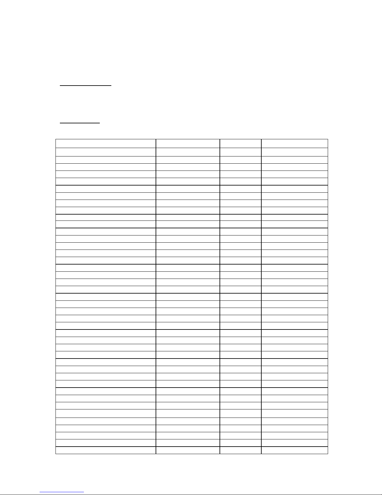
Installer Settings Summary
Setting
Range
Default
Display Lock
Y or N
N
Locks out front buttons
Service Mode Submenu
Test Mode
Y or N
N
Reduces delays for testing
System Settings Submenu
Mechanical Settings Submenu
Sys Type
Std or HP
Std
Fan Type
Gas or Elec
Gas
C/O Type
w/Heat or w/Cool
w/Cool
2nd Stage Heat
Y or N
N
Aux Heat
Y or N
Y
2nd Stage Cool
Y or N
N
H/C Delta
3 – 15 deg
3
Heat Delta Stage 1 On
1 – 8
1
Heat Delta Stage 1 Off
0 – 8
0
Heat Delta Stage 2 On
1 – 8
2
Heat Delta Stage 2 Off
0 – 8
0
Heat Delta Stage 3 On
1 – 8
3
Heat Delta Stage 3 Off
0 – 8
0
Cool Delta Stage 1 On
1 – 8
1
Cool Delta Stage 1 Off
0 – 8
0
Cool Delta Stage 2 On
1 – 8
2
Cool Delta Stage 2 Off
0 – 8
0
Max Heat SP
40-109F (4-42C)
90F
Min Cool SP
44-113F (6-45C)
60F
Min Run Time
1-9 min
3
Min Off Time
1-9 min
5
Temp Response
1-6
2
Fan Cycler Submenu
Fan Cycler ON time
0 – 120 min
0
0 = Fan Cycler OFF
Fan Cycler Off Time
10 – 120 min
10
Restore Defaults
Yes or No
No
No on exit
USER SETTINGS
Filter Service Submenu
Service Interval
Disabled, 100-4000 hrs
300
Maint Service Submenu
Maint Interval
Disabled, 100-4000 hrs
3000
Screen Timeout (to minimized screen)
0, 20-120 sec
0
0 = off
F/C Mode
F or C
F
Sensor Calibration Submenu
Internal -7 to +7
0
Backlite/Display Submenu
Backlite Timeout
0, 20-120
0
0 = backlite off
Contrast
0-20
14
Page 6
DCN: 140-02034-03 Page 6
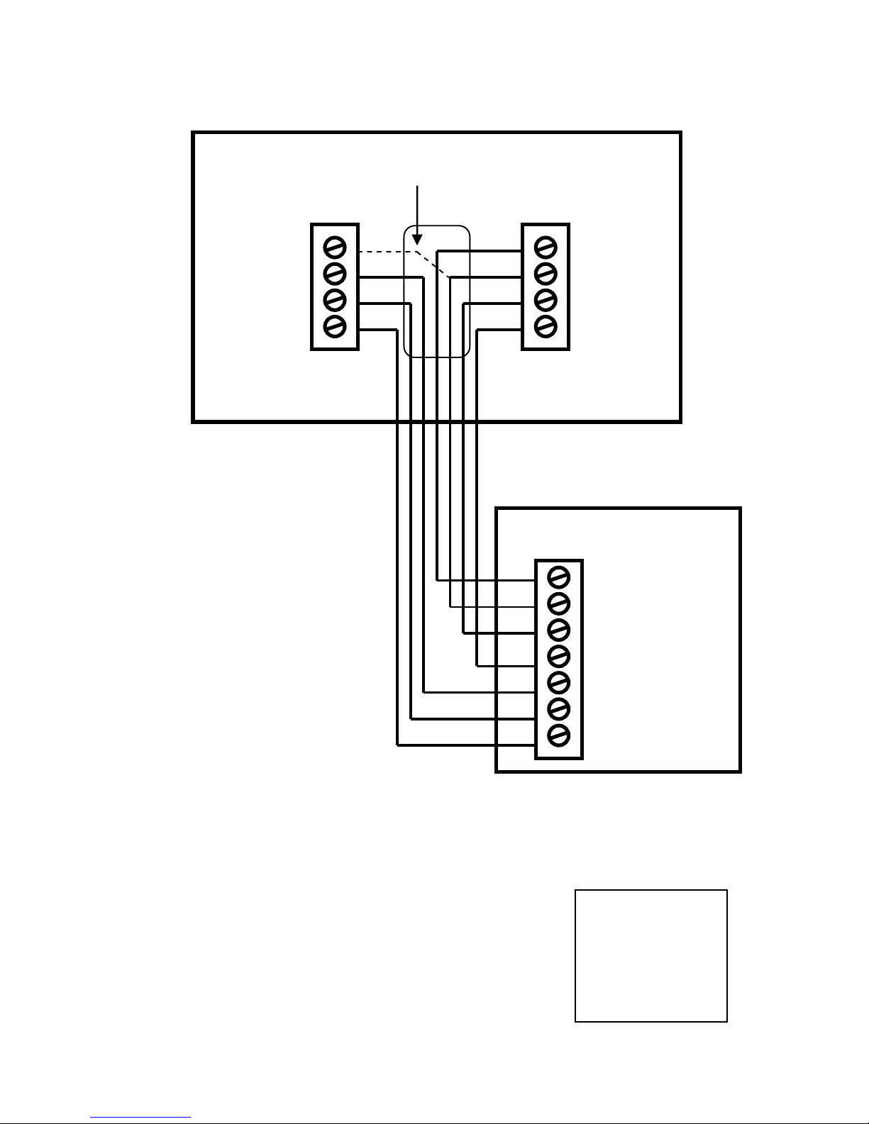
Standard Gas/Electric HVAC System Wiring
Thermostat Setup: Standard Gas/Electric HVAC Systems
To set the HVAC system type, go to the Thermostat Info screen Setup or the Installer Settings menu
(a hidden screen – go to the main menu screen and press and hold the center two buttons for 5 seconds)
In the Installer Settings Menu, Select System Settings then select Mechanical Settings and set the following:
1. Type. Set the HVAC System Type: set to Gas/Elec
2. Fan Type. Set the HVAC Fan Type:
Set to Gas for typical gas furnace (fan is controlled by the furnace)
Set to Elec for electric heat (fan call with heat call)
3. C/O type. Not used for standard systems. Ignore this setting.
4. 2nd Stage Heat. Enable second stage heating outputs
If you have a single stage heating system, leave this set to N
If you have a 2 stage heating system, set to Y to enable.
5. Aux Heat (HP). Not used for standard systems. Ignore this setting
6. 2nd Stage Cool. Enable second stage cooling outputs
If you have a single stage cooling system, leave this set to N.
If you have a two stage cooling system , set to Y to enable.
Default Setup:
Standard System
Gas Heat
1 Stage heating
1 Stage cooling
No setup required for
this configuration
Standard HVAC System
W1
G
W2/O
Y1
24C
24RH
24RC
Y2
24V R Cooling
Fan
Cooling stage 1
Cooling stage 2
24V Com
24V R Heating
Heating stage 1
Heating stage 2
Optional 24R Connection for single transformer HVAC Systems
RC and RH are jumpered together on thermostat board.
Cut RC/RH jumper JP1 for separate heating and cooling transformers
Fan
Heating Stage 1
Cooling Stage 1
24VAC Return
24VAC Common
Thermostat Connection Terminals
Cooling Stage 2
Heating Stage 2
C
R
G
W1
Y1
W2
Y2
Page 7
DCN: 140-02034-03 Page 7
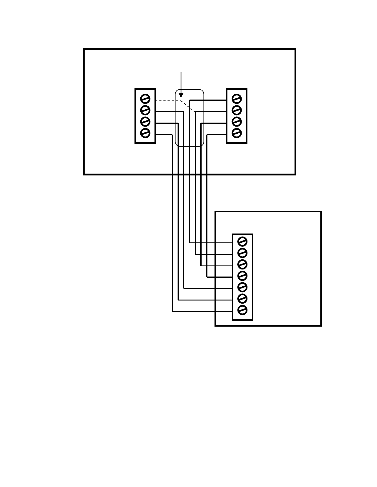
Heat Pump HVAC System Wiring
Thermostat Setup: Heat Pump HVAC Systems
To set the HVAC system type, go to the Thermostat Info screen Setup or the Installer Settings menu
(a hidden screen – go to the main menu screen and press and hold the center two buttons for 5 seconds)
In the Installer Settings Menu, Select System Settings then select Mechanical Settings and set the following:
1. Type. Set the HVAC System Type: set to Heat pump
2. Fan Type. Automatically set for Heat Pump systems. Ignore this setting
3. C/O type. Change Over valve energizes either with cool calls or with heat calls. You must configure the
thermostat’s changeover valve setting to work correctly with your HVAC system. Check your system information to
be sure. Note the color of the wire (Orange or Brown) and to which terminal (O or B) on the old thermostat the
wire was connected to. No matter what the old stat connection was, connect the wire to the W2/O terminal on the
TZ45. The setting for C/O type will set the correct system operation.
For change over with cool systems (old stat O terminal/orange wire) = set to w/cool (most common
type and default setting)
For change over with heat systems (old stat B terminal/brown wire) = set to w/heat
Note: If you get cooling when you expect heating, change the C/O type to the opposite setting
4. 2nd Stage Heat. Enable second stage heating outputs
If you have a single stage heating system, leave this set to N
If you have a 2 stage heating system, set to Y to enable.
5. Aux Heat (HP). If you have auxiliary heat strips, set this to Y (default setting), if not, set to N
6. 2nd Stage Cool. Enable second stage cooling outputs
If you have a single stage cooling system, leave this set to N.
If you have a two stage cooling system, set to Y to enable.
Heat Pump HVAC System
W1
G
W2/O
Y1
24C
24RH
24RC
Y2
24V R Cooling
Fan
Compressor stage 1
Compressor stage 2
24V Com
24V R Heating
Aux Heating
Changover Valve
(reversing Valve)
Optional 24R Connection for single transformer HVAC Systems
RC and RH are jumpered together on thermostat board.
Cut RC/RH jumper JP1 for separate heating and cooling transformers
Fan
Aux heating
Compressor Stage 1
24VAC Return
24VAC Common
Thermostat Connection Terminals
Compressor Stage 2
Changeover Valve
C R G
W1
Y1
O/B
Y2
Page 8
DCN: 140-02034-03 Page 8
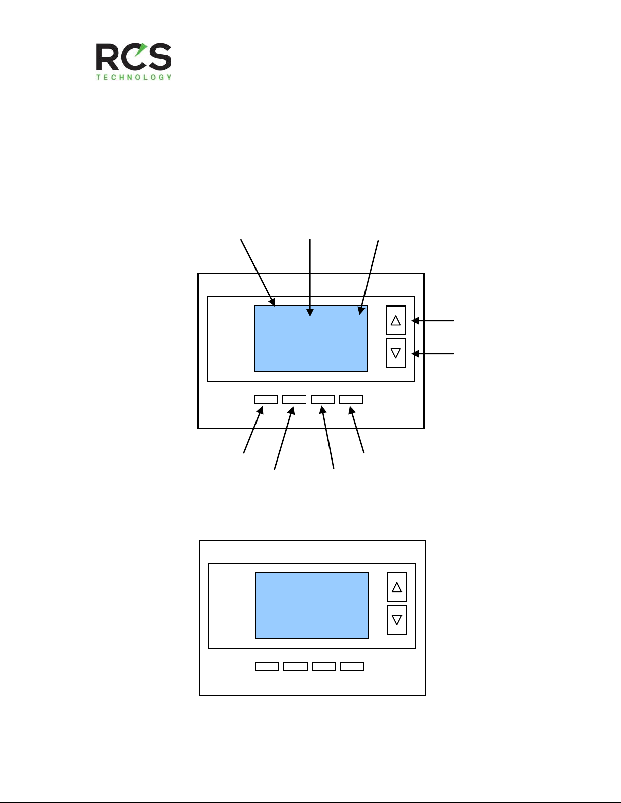
Operation Guide
Model TZ45A
Z-Wave Thermostat
Temperature
Setting
Warmer
Cooler
Fan Mode
Selection
Heating/Cooling
Mode Selection
Home/Away
Mode Selection
Menu
Selection
Room Temperature
Setpoints
Backlite Display
Main Thermostat Screen
Minimized Display
Press any button to return to the main thermostat screen
75
MENU
HEAT
MODE
HOME
64H
82C
AUTO
FAN
Sys Off
75
Page 9
DCN: 140-02034-03 Page 9
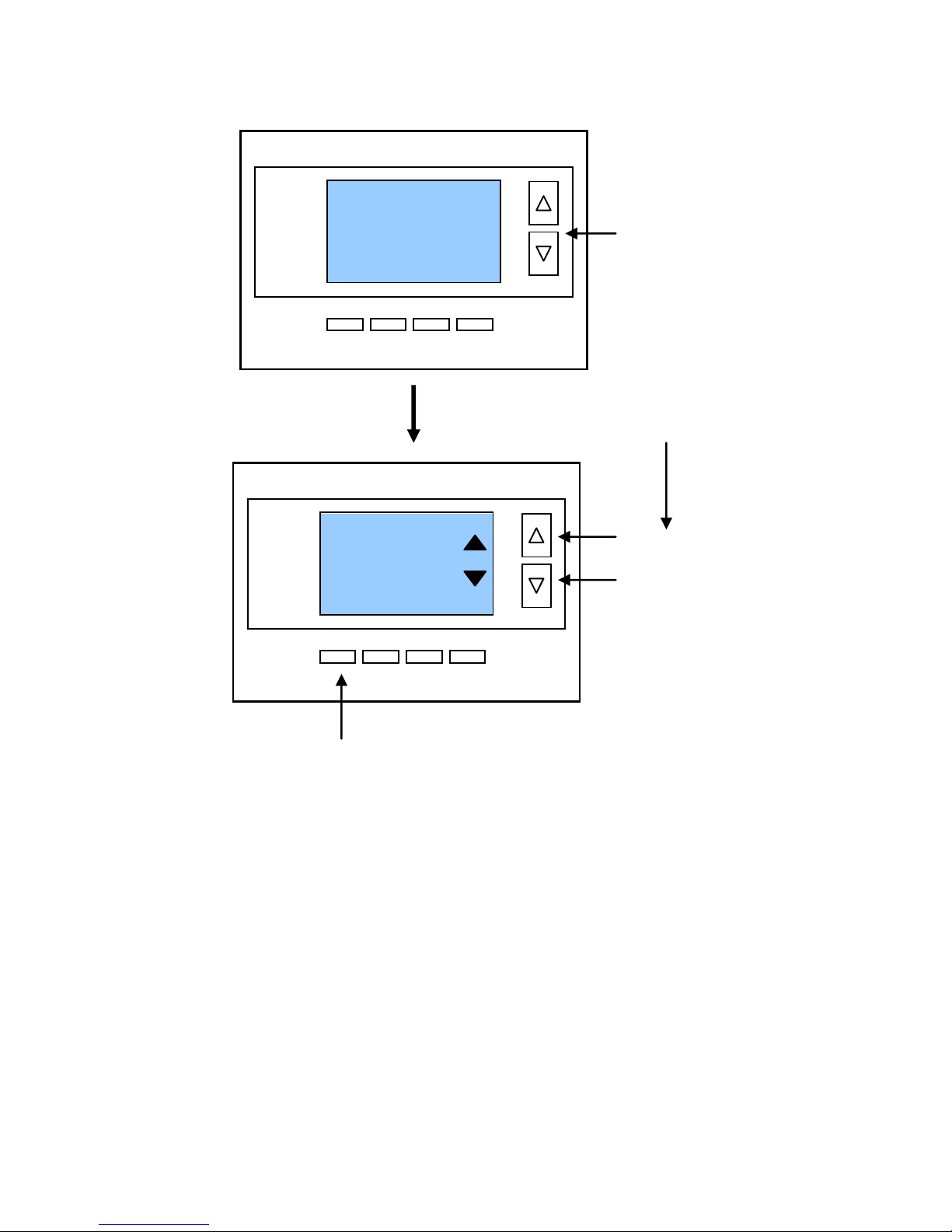
Setting the heating or cooling temperature setpoint
! If the System Mode is OFF, pressing either the Up or Down buttons will take you
to the System Mode screen. You must first set an operating mode before you can
set or change the setpoint.
! To change the Heat Setpoint you must be in the Heating mode, to change the Cool
Setpoint you must be in the Cooling mode. If you are in Auto mode, the mode of the
last system call will be the setpoint screen displayed.
Setpoint Push: Note that you cannot lower the cooling setpoint below the heating
setpoint. The thermostat will “push” the heating setpoint lower if you try to lower the
cooling setpoint below the heating setpoint. It maintains a 3 degree separation between
the heating and cooling setpoint. The same is true for raising the heating setpoint above
the cooling setpoint. Again the thermostat will “push” the cooling setpoint up to maintain
the 3 degree separation.
Lower Temperature
Raise Temperature
Press a button to
go to the setpoint
change screen
64
DONE
Setpoint change screen
Press “DONE” button to set the setpoint and exit back
to the main thermostat screen or wait for the screen to
automatically time out.
Press the up or down arrow buttons to
set the desired temperature setpoint
HEATING SETPOINT
Pressing the up
or down buttons
will increment the
setpoint 1 degree.
Press and hold
the button to
ramp the setpoint.
75
MENU
HEAT
MODE
HOME
64H
82C
AUTO
FAN
Sys Off
70
Done
HEATING SETPOINT
Page 10
DCN: 140-02034-03 Page 10
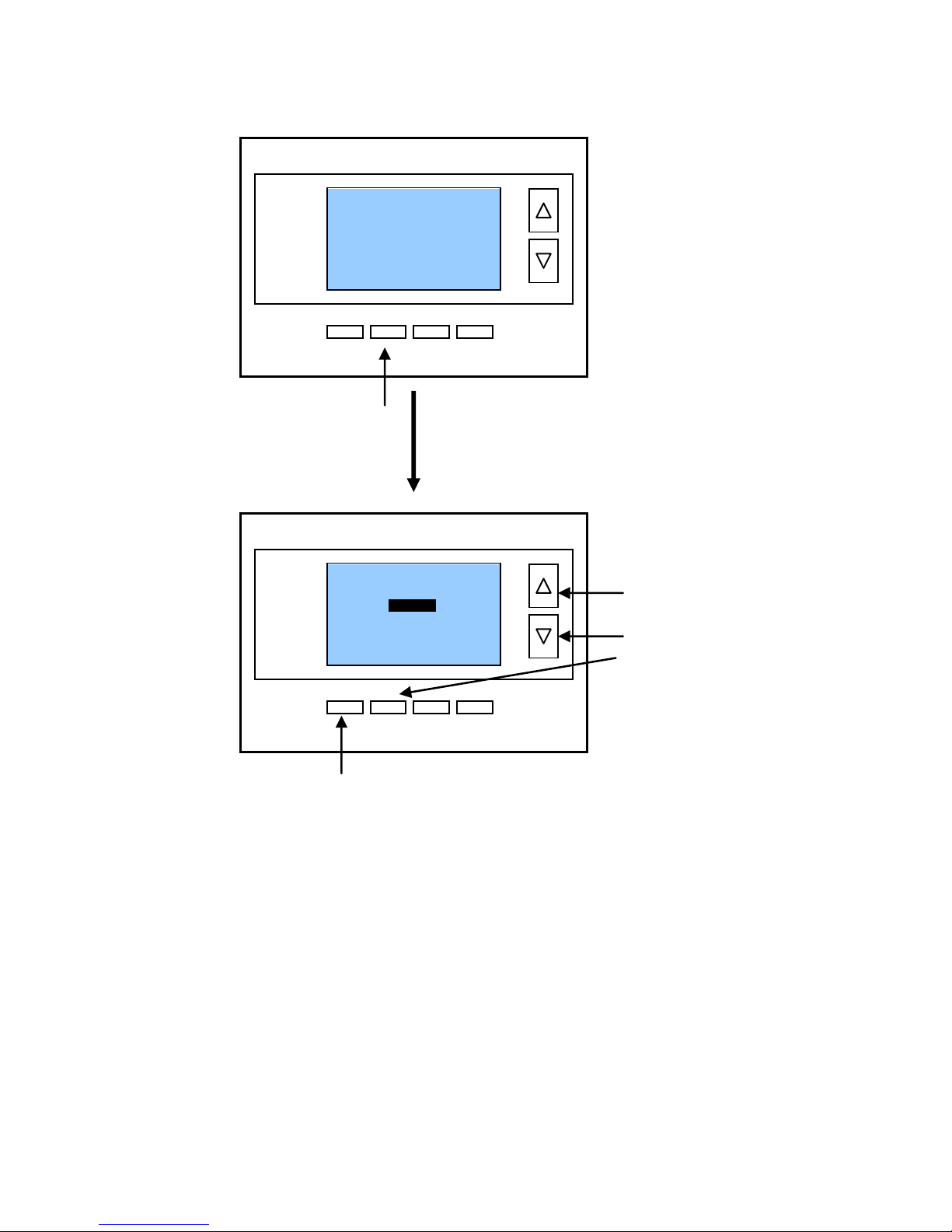
Setting the System Mode: Off, Heat, Cool, Auto
System Modes
OFF Mode: System is off. No heating or cooling will come on. If system was
on, it will turn off immediately.
HEATING Mode: Only heating will occur.
COOLING Mode: Only cooling will occur.
AUTO Mode: Heating or cooling will come on according to the heating and
cooling setpoints. The system will automatically switch between heating and
cooling modes as needed to maintain the setpoints.
! Special Heat Pump Mode: Emergency Heat
EHEAT Mode: An additional system mode, “EHEAT” for Emergency Heat will be
displayed if the HVAC system type is set to Heat Pump. If there is a compressor
failure with the Heat Pump system, setting the mode to EHEAT will allow the
supplemental Aux heat to come on first whenever there is a call for heating. It also
disables the compressor output to prevent further damage to the HVAC system.
Press the
UP or
DOWN buttons
or
MODE button
to select the
desired system
mode.
System Mode change screen
Press Mode button to
change system mode
Press “DONE” button to select the mode and exit back to
the main thermostat screen or wait for the screen to
automatically time out.
75
MENU
HEAT
MODE
HOME
64H
82C
AUTO
FAN
Sys Off
Done
MODE
SYSTEM MODE
OFF
HEATING
COOLING
AUTO
Page 11
DCN: 140-02034-03 Page 11
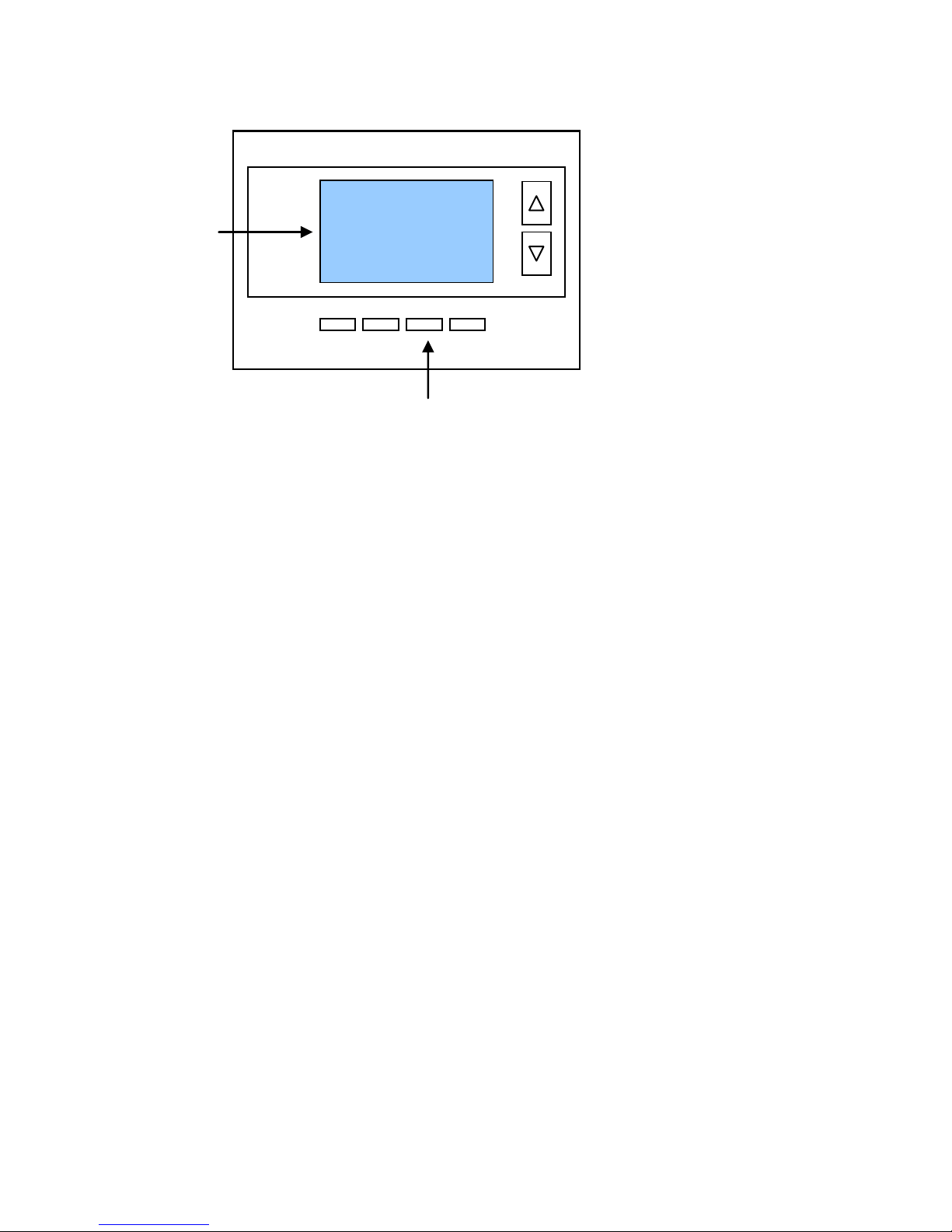
Setting Fan Mode and System Status Indicators
Optional Fan Mode
Fan Cycler. If the Fan Cycler feature is enabled in the Installer Setup, the additional fan
mode “Cycle” will be shown in the Fan Mode menu. This mode cycles the fan on and off
continuously for fresh air ventilation according to the settings in the Installer Setup.
System Status Indicators
When the main thermostat screen is displayed, the on-screen labels indicate the following.
System Operation mode indicator
“SYS OFF” displayed > System is OFF
“SYS MOT”
1
displayed > System is OFF and Minimum Off Time (MOT) delay On is active
“HEAT ON” displayed > System is ON and heating
“COOL ON” displayed > System is ON and cooling
“HEAT MRT”
2
displayed > System is ON and heating. Minimum Run Time (MRT) delay off
is active.
“COOL MRT” displayed > System is ON and cooling. Minimum Run Time (MRT) delay off
is active.
Staging display
“2
nd
Stg” displayed > Stage 2 heating or cooling is ON
“Aux Heat” displayed > Stage 3 heating is ON
For Heat Pump systems only: “EHEAT” > emergency heat mode active
Home/Away display
Home mode is active (current setpoints are being used)
Away setback mode is active (setback setpoints are being used)
System Alerts
Alert Text displayed > Specific alert text (Filter or Maintenance Timer)
Notes 1 and 2: See MOT and MRT descriptions on page 7
Press the Fan button to change the Fan mode
AUTO FAN: Fan automatically operated by the HVAC system.
FAN ON: Manual Fan mode. Fan stays on until mode is changed back to Auto.
System
Status
Indicators
75
MENU
HEAT
MODE
HOME
64H
82C
AUTO
FAN
Sys Off
2nd Stg
Filter
Page 12
DCN: 140-02034-03 Page 12
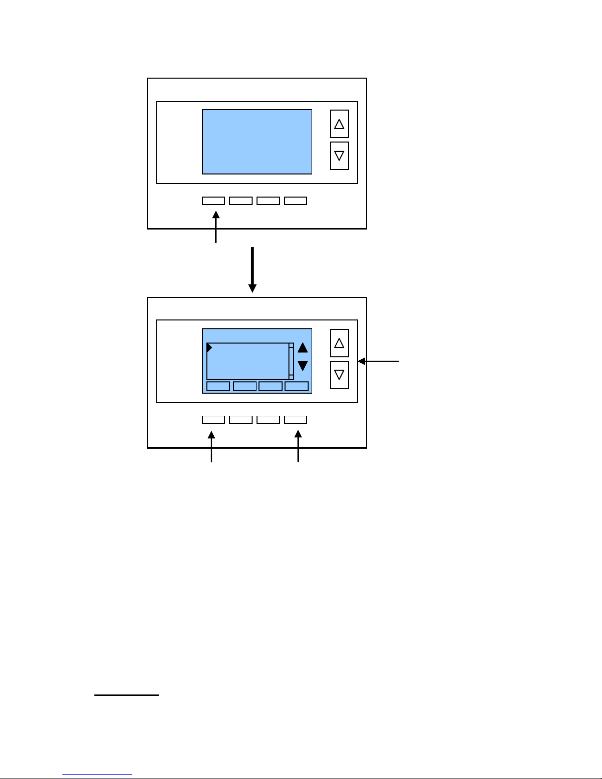
Menu Selection
Main Menu Items
User Settings > set various user preferences
Away Setpoints > show and set the heating and cooling setback setpoints
ZWave Install > ZWave installation
Thermostat Info > displays thermostat setup info
User Settings menu items
Filter Service > go to the filter timer setup screen
Maint Service > go to the maintenance timer setup screen
Screen Timeout > sets the time in seconds to switch to the minimized screen
F/C Settings > go to the F/C mode selection screen
Sensor Calibration > go to the sensor calibration screen
Backlight/Display > go to the backlight and display setup screen
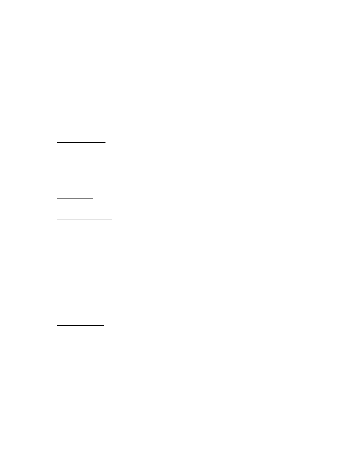
Filter Service: Go to the Filter Service Screen. Sets/resets the filter timer/alert.
Shows filter runtime in hours and the service interval alert in hours (typically 300 hrs)
Change the service interval with the +/- buttons.
Reset the service alert after you have changed the filter.
Press Menu button to go
to the main menu screen
Use the
UP/DOWN
buttons to select
the desired menu
item
Press SELECT to go to the
menu item screen
Press DONE to go back to
the main thermostat screen
75
MENU
HEAT
MODE
HOME
64H
82C
AUTO
FAN
Sys Off
Menu Selection
Select
User Settings
Away Setpoints
ZWave Install
Thermostat Info
Done
Page 13
DCN: 140-02034-03 Page 13
Maint Service: Go to the Maintenance Service Screen. Sets/resets the maintenance
timer/alert.
The Maintenance Service screen will show the accumulated Heat and Cool runtime hours
as well as the Service Interval that will be used to trigger a Maintenance alert.
Service interval is 3000 hours. Use the +/- buttons to adjust service interval.
Press reset to clear the service alert and reset the runtimes to zero.
When the combined HEAT and COOL Runtime hours equals the Service Interval hours,
the Red LED will flash along with a “Maint” message to remind you your HVAC system
may require periodic maintenance. Pressing the Menu button will take you to the Filter
Service screen. The Reset button can be pressed and the HEAT and COOL Runtime
values will be reset to zero.
Screen Timeout: Minimized Screen. Set the display timeout time in seconds. Options
are 0 or 15 to 120 (default set to 0 seconds). This is the time before the main thermostat
screen reverts to the minimized temperature only display screen, after the last button
press. The Minimized Screen feature is disabled by setting this time to “0”.
! Any button press will restore the main thermostat screen display.
F/C Settings: Go to the F/C Settings Screen. Select which temperature display mode
you desire, Fahrenheit (F) or Celsius (C).
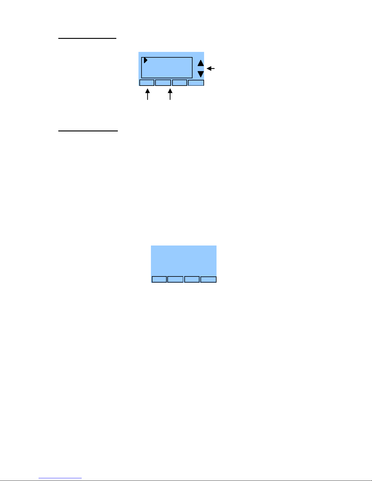
Sensor Calibration: Go to the Sensor Calibration Screen. This screen allows you to
adjust the calibration of the internal sensor. You can change the temperature calibration
by +/- 7 degrees using the + and – buttons
When the Sensor Calibration screen is selected it will show the current temperature
calibration and the current number of degrees of offset being applied (typically 0). If the
sensor’s actual temp is (74) with 0 degrees of offset and you want it to show 75, then press
“+” to add 1 deg and it will show (75).
! You can refresh the info on this screen by pressing the right hand (blank) button.
When you close this screen, it may take a few seconds for the temperature displayed on
the main thermostat screen to update to the new temperature selected.
Backlite/Display: Go to the Backlite/Display settings screen. This menu allows you to set
the backlight timeout period and adjust the display contrast.
Backlite Timeout: Sets the time from last button press that the backlite will timeout and
turn off. The timeout value is adjustable from 0 or 20 to 120 seconds. If set to “0”, the
Backlite will always be ON. If set in the range of 20 to 120 seconds, the Backlite will turn
OFF after the selected time expires.
Contrast: Sets the contrast level of the LCD display, adjustable from 0 to 20. Use this
control to adjust the darkness of the display. To light and the display looks faded, too dark
and dark lines will appear in the display. Typically 10-15 is a good setting. Adjust as
needed.
Page 14
DCN: 140-02034-03 Page 14
Away Setpoints
Away setpoints are used when the thermostat is set to the setback or away mode.
Thermostat Info
The Thermostat Info screen displays the current configuration of the Z-WAVE Thermostat.
This information is useful for quick check of firmware versions and HVAC system setup. It
also shows the ZWave network setting.
Thermostat information displayed is:
Thermostat - Model and firmware version number.
Z-Wave Settings – ZWave Firmware version, ZWave Node ID, ZWave Home ID
System Type - Standard or Heat Pump HVAC system
Fan Type – if HVAC type = Standard: Gas or Elect
OR
Changeover – if HVAC type = Heat Pump: Changeover with cool or changeover
with heat.
Thermostat Info Screen
Thermostat Operation
Minimum Run Time (MRT)
The thermostat has a Minimum Run Time after the start of any heating or cooling call.
This minimum run time assures even heating and cooling cycles. The MRT delay will keep
the system on even if reaches setpoint or you change the setpoint to a temperature that
would satisfy the call, until the MRT expires. Changing the Mode to OFF will cancel the
MRT and the system will turn off immediately. The MRT can be adjusted in the Installer
Settings menu of the thermostat.
Note: The MRT status is shown in the thermostat System Status on-screen labels.
Minimum Off Time (MOT)
The thermostat has a Minimum Off Time after any heating or cooling call is finished. This
delay prevents rapid heating/cooling cycles and also provides “short cycle protection” for
compressor calls. This delay may be noticeable when you change a setpoint and it does
not respond immediately due to another call that has recently completed and the MOT
delay timer is preventing the system from restarting. The MOT delay time can be adjusted
in the Installer Settings menu of the thermostat. There is a minimum of 5 minutes delay to
assure compressor protection.
Note: The MOT status is shown in the thermostat System Status on-screen labels.
Press Done button to exit
back to Main Menu screen.
DONE
Away – Heat 65
Away – Cool 80
Away Setpoints
+
-
Use up/down buttons to select
setpoint to change
Use +/- buttons to increase or
decrease the temperature
Press DONE to store the
setting and exit back to the
main menu
Done
Setup
TZ45A Ver 1.00.00
ZVER: 2.97 ZNID: 001
ZHID: 00.00.07.76
System Type: Standard
Fan Type: Gas
Thermostat Info
Status
Press and Hold Status button
to enter Relay Status screen.
Press and Hold Setup button
to enter Mechanical Settings
screen. NOTE: For qualified
service personnel only, see
Page 3 of Installation Guide.
Page 15

DCN: 140-02034-03 Page 15
Z-Wave® Installation
Z-Wave controllers from various manufacturers may support the Z-Wave Thermostat
General V2 Device class used by the RCS Z-WAVE Thermostat. The following procedure
will allow the thermostat to be added to a Z-Wave network.
General Programming Procedure (for controllers supporting the thermostat device
class):
1. Set your primary controller to Include, Add or Install mode, to add the
thermostat as a node on your network (see your controller’s user manual for
detailed instructions).
2. In the Thermostat’s Main Menu, scroll down to the ZWave Install item.
Select the item.
3. When prompted by your Z-Wave controller, Press the YES button in the
ZWave Install screen.
Your controller will indicate the thermostat was successfully added to its network (see
your controller’s user manual for details). Also you can check if the thermostat was
successfully added to the network by checking the ZHID (Home ID) and ZNID (Node
ID) located in the Thermostat Info screen.
For other specific tasks such as adding the thermostat to Scenes or Groups, or
deleting the thermostat from an existing network, use the Z-Wave Install procedure.
Note: Before adding the thermostat to a Z-Wave Network, check that it does not
already belong to one by viewing the Node ID (ZNID) located in the Thermostat Info
screen. An un-installed thermostat should show zeros for the Node ID (000). Consult
your controller’s user manual for details on removing a device from a Z-Wave
network.
Setback Mode Operation
If your controller does not support full thermostat device class functions, it may still be able
to control the energy saving AWAY mode of the thermostat through BASIC_SET
commands.
Sending the BASIC_SET (Value = 0x00), the thermostat will go into the AWAY mode and
use the predefined AWAY setback setpoints. These setpoints are set in the Main Menu
Away Setpoints item.
Sending the BASIC_SET (Value = 0xFF), the thermostat will revert back to the Home
mode it was in before the BASIC_SET (Value = 0x00) command was sent.
Note that when the BASIC_SET commands are sent, the TZ45 will momentarily display
the new mode.
Inclusion and Exclusion
Inclusion or exclusion is started by putting the controller into add node or remove node
state and performing the General Programming Procedure outlined above. As part of the
process, the thermostat sends a node information frame at normal power.
Low power inclusion or low power exclusion is not possible.
Page 16

DCN: 140-02034-03 Page 16
FCC
INFORMATION TO USER
This device complies with Part 15 of the FCC Rules. Operation is subject to the following
two conditions: (1) This device may not cause harmful interference, and (2) This device
must accept any interference received, including interference that may cause undesired
operation.
This equipment has been tested and found to comply with the limits for Class B Digital
Device, pursuant to Part 15 of the FCC Rules. These limits are designed to provide
reasonable protection against harmful interference in a residential installation. This
equipment generates and can radiate radio frequency energy and, if not installed and used
in accordance with the instructions, may cause harmful interference to radio
communications. However, there is no guarantee that interference will not occur in a
particular installation. If this equipment does cause harmful interference to radio or
television reception, which can be determined by turning the equipment off and on, the
user is encouraged to try to correct the interference by one or more of the following
measures.
Reorient or relocate the receiving antenna
Increase the separation between the equipment and receiver
Connect the equipment into an outlet on a circuit different from that to which the
receiver is connected
Consult the dealer or an experienced radio/TV technician for help
Any changes or modifications not expressly approved by the party responsible for
compliance could void the user’s authority to operate the equipment.
 Loading...