

Page 1
RCS
Model TR65
RS485 Thermostat
OPERATION MANUAL
DCN: 141-02165-01
5/03/12
1
Page 2

Model: TR65
Product
Part No:
Firmware Revision
TR65 RS485 Thermostat
001-02165
Includes
TS65 Wall Display Unit
001-02102
ZCV1 HVAC Control Unit
001-01065
Revision
Date
Changes
01
5/03/12
Original release
RS485 Thermostat
This manual applies to the following product revisions or later revisions up to the next manual revision
release:
Document Revision History
Product Specifications
Product Model: TR65
Product: Thermostat for Heating and Cooling HVAC System control.
RS485 Half Duplex 2 wire (plus gnd) communications
Wall Display Unit
Model: TS65
Size: 5.7” wide x 4.0” height x 1.2” depth
Display: Graphical LCD, 2.75” x 1.5”, 64x128 pixel
Backlight: Yes, Blue/white, Controllable, on, off, timeout
Contrast: Adjustable on screen
Buttons: 6
LEDs: 4 (3 green, 1 red)
Remote Sensors: 2, two wire, remote primary, averaging
Power: 12VDC from HVAC Control Unit
HVAC Control Unit
Model: ZCV1
Size: 8” x 6” x 1.5”
HVAC System Type Compatible: Standard (gas/electric) or Heat Pump
Multistage System Compatible:
Standard HVAC Systems: 2 stage heating, 2 stage cooling
Heat Pump Systems: 3 stage heating (2 compressor, 1 aux heat), 2 stage cooling
Heat Pump change over valve: Selectable change over with cool or with heat ( O or B)
Communications: RS485 Half Duplex 2 wire (plus gnd)
Power: 24VAC from HVAC system
2
Page 3

Table of Contents
Overview ...................................................................................................................................................... 4
Thermostat Control Screen ........................................................................................................................ 5
Temperature Display ................................................................................................................................. 5
Setpoint Display ......................................................................................................................................... 6
Thermostat Operation Buttons .................................................................................................................. 6
Pressing these buttons will take you to the following screens: .................................................................. 6
Setpoint Up/Down Buttons ......................................................................................................................... 6
Press either the Up or Down buttons to go to the Heating or Cooling Setpoint screen. ............................ 6
Time Display .............................................................................................................................................. 6
LED Displays ............................................................................................. Error! Bookmark not defined.
Heating/Cooling Setpoint Setting .............................................................................................................. 7
Setting Heating or Cooling Setpoints ......................................................................................................... 7
System Mode ............................................................................................................................................... 8
Setting the System Mode ........................................................................................................................... 8
Fan Mode ..................................................................................................................................................... 9
Setting the Fan Mode ................................................................................................................................ 9
Schedule Operation .................................................................................................................................. 10
Setting the Schedule Mode ...................................................................................................................... 10
Main Menu .................................................................................................................................................. 11
Main menu - Schedules ............................................................................................................................ 12
Thermostat Schedule Selection ............................................................................................................... 12
Main Menu - Schedules - Heat and Cool Schedule Screen ................................................................... 13
Schedule Edit Screen .............................................................................................................................. 13
Main Menu - Schedules - Heat and Cool - Copy Schedule .................................................................... 14
Copying a Day Schedule to another Day ................................................................................................. 14
Main Menu - User Settings ....................................................................................................................... 15
Main Menu - User Settings - Set Clock ................................................................................................... 16
Main Menu - User Settings - Filter Service ............................................................................................. 17
Main Menu - User Settings - Maint Service ............................................................................................. 18
Main Menu - User Settings - Sensor Calibration .................................................................................... 19
Main Menu - User Settings - Backlite/Display ........................................................................................ 20
Main Menu - Thermostat Info ................................................................................................................... 21
Main Menu – SmartVent (optional) .......................................................................................................... 22
Main Menu – Messaging (optional) ......................................................................................................... 25
Main Menu > Installer Settings (Hidden Screen) ................................................................................. 26
3
Page 4
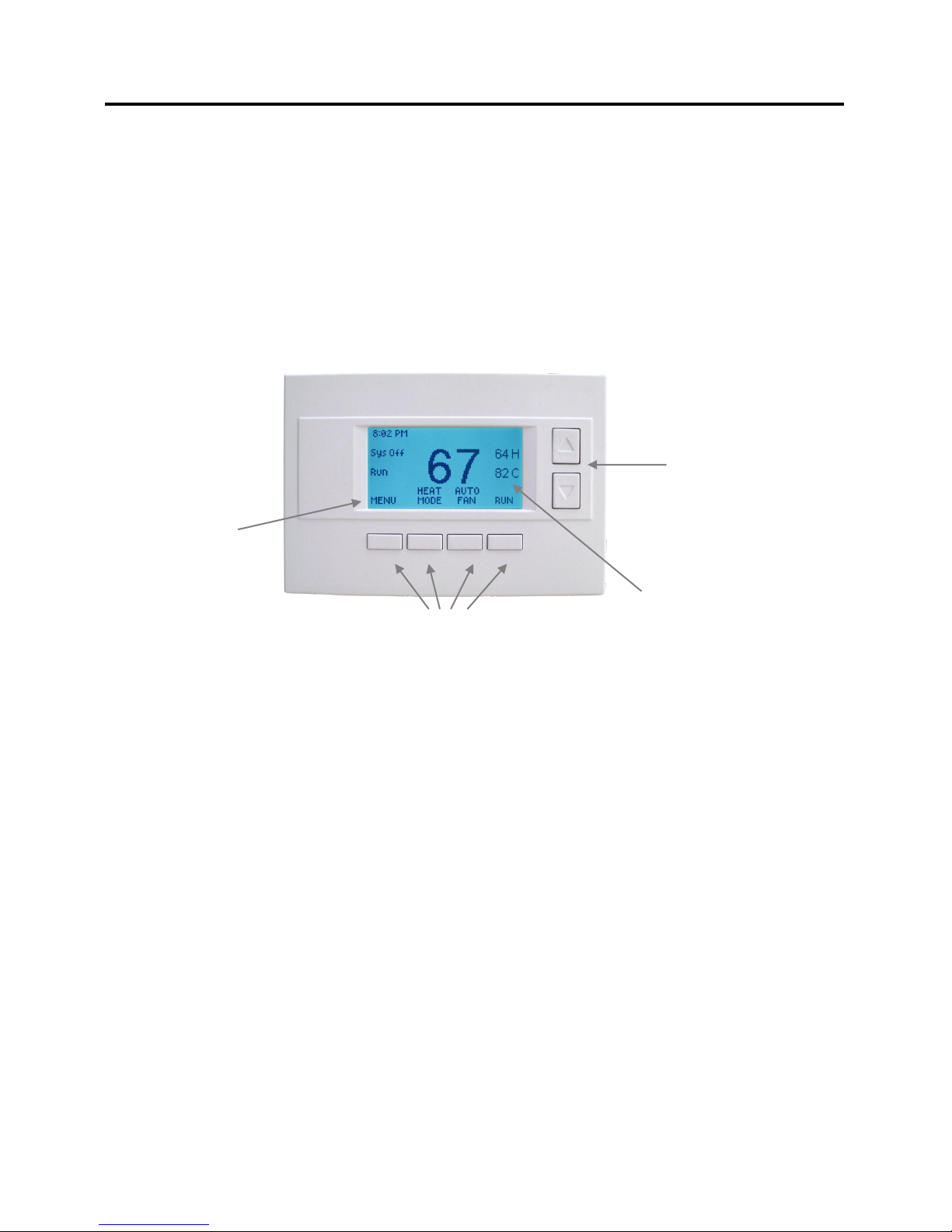
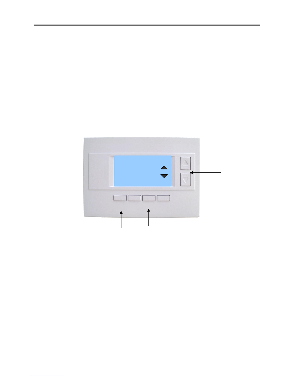
Setpoint
Up/Down
Buttons
Function Control Buttons
Heating (H)
And
Cooling (C)
Setpoints
On-screen
dynamic
button labels
Overview
RS485 Thermostat
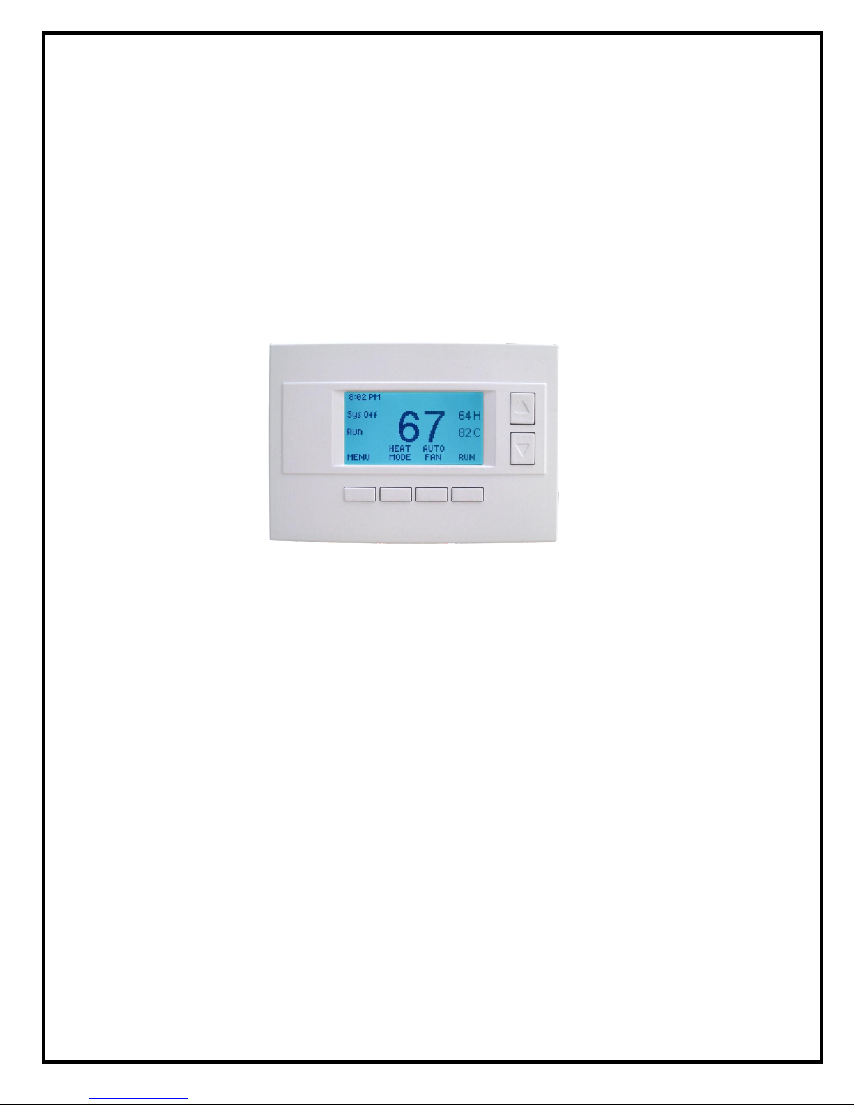
The TR65 thermostat provides typical thermostat control of a central heating and cooling HVAC system
plus has the added feature of RS485 communications for remote control. The TR65 is a two part
thermostat with a Wall Display Unit and a HVAC Control Unit.
The Wall Display Unit (WDU) has a large, backlit graphical display, control buttons, status LEDs and a
temperature sensor. The WDU can display multiple screens for different functions of the thermostat. In
the default thermostat control screen, shown below, it displays the current room temperature, heating and
cooling setpoints, system mode, manual fan mode, time, and status information.
Display operation
Thermostat control screen
Normally the thermostat displays the thermostat control screen as shown above. Using the “Menu”
button, you can access other screens and functions of the thermostat.
Minimized Display Mode
Optionally, you can set the thermostat to show only the temperature in a “minimized” display mode.
This mode can be set on or off in the thermostat “Us ers Settings” menu.
Backlight
The thermostat has a backlit display for low light and night visibility. It can be set to remain on constantly,
or to turn off after a 20-120 second delay. These are selectable in the User Settings menu.
Function Control Buttons
The thermostats buttons are “Soft Keys” meaning that they change functions when you change screens.
The function of the button is defined by “on-screen labels” that are dynamic and change when you change
screens
4
Page 5
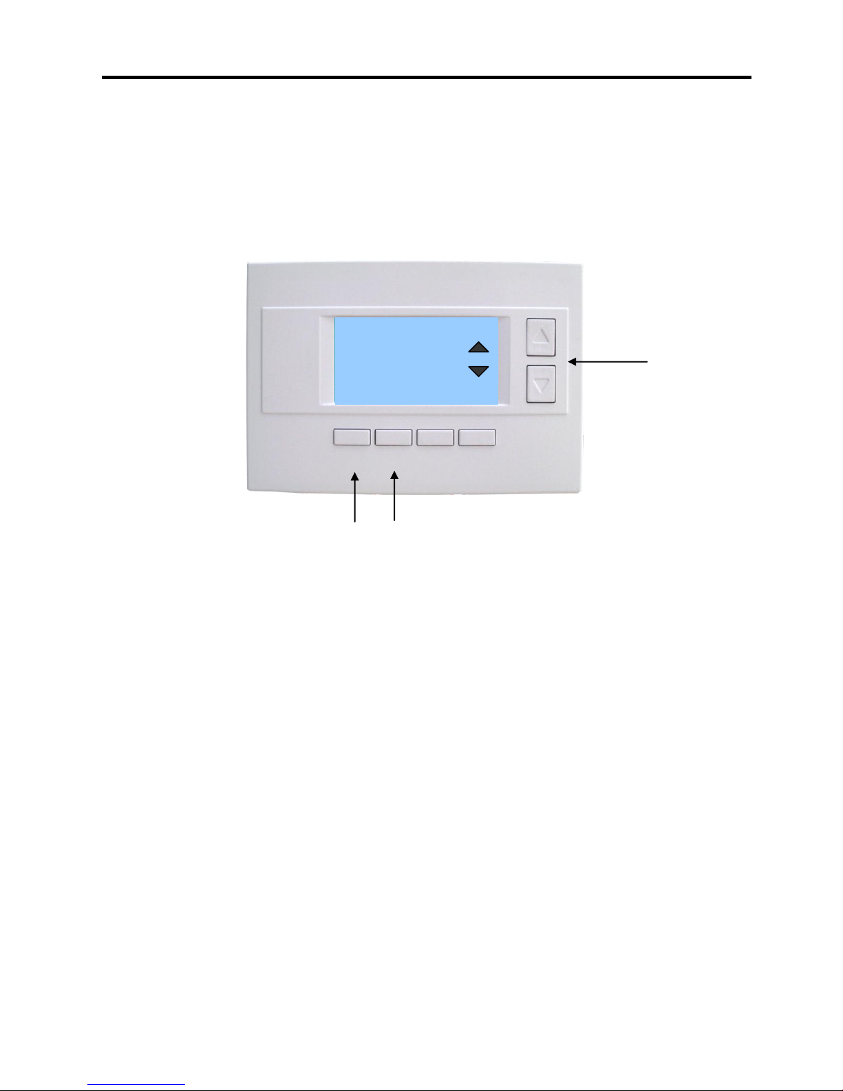
75
Press any button to return to
the thermostat control screen
The Minimized Screen
shows only the room
temperature.
It is displayed if you set the
“Screen Timeout” in the
User Settings Menu to a
time greater than 0.
If set to 0, the minimized
screen is disabled, and the
main thermostat screen is
normally displayed
MENU
COOL
MODE
72 H
AUTO
FAN
HOLD
74
75 C
4:30 PM
SYS OFF
ECON
HOLD
NO MSG
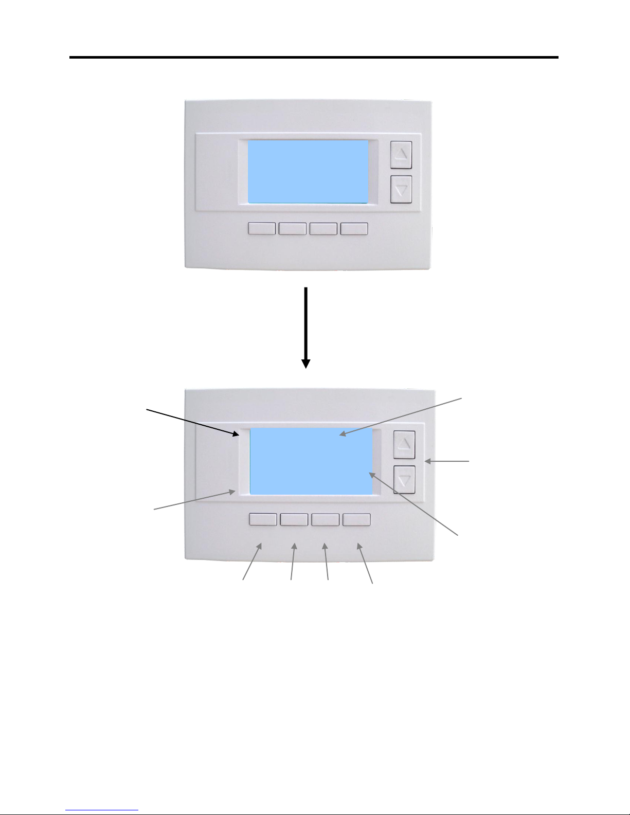
On-screen
dynamic
button labels
Setpoint
Up/Down
Buttons
Heating (H)
And
Cooling (C)
Setpoints
Main
Menu
System
Mode
Fan
Mode
Schedule
Mode
Outside 85
Outside
Temperature
Display
Time
Display
Minimized Screen
Main Thermostat Control Screen
The main Thermostat Control Screen is the screen that is normally displayed on the thermostat.
Temperature Display
The thermostat will normally display the current room temperature from the internal temperature sensor
(or a remote sensor, if installed).
Outside Temperature Display
It the thermostat has an outside temperature sensor installed, the outside temp will be displayed.
Thermostat Control Screen
5
Page 6

Setpoint Display
The current heating and cooling setpoints are displayed next to the Setpoint Up/Down buttons.
Thermostat Operation Buttons
Pressing these buttons will take you to the following screens:
Menu – go to the Main Menu Screen to select other thermostat
settings screens.
System Mode – go to the Sy stem Mode screen to set
thermostat operating mode.
Fan Mode – go to the Fan mode screen to set the fan mode.
Schedule Mode – go to the Schedule mode screen to set
schedule mode or setback.
Setpoint Up/Down Buttons
Press either the Up or Down buttons to go to the Heating or Cooling Setpoint screen.
NOTE: If the thermostat is in the OFF mode, pressing the setpoint Up/Down buttons will take you
to the System Mode Screen. You must first select an operating mode to be able to change the
setpoint for that mode.
Time Display
The current time is displayed in the upper left corner of the main screen. Set the clock from the User
Settings Menu. The time will blink when the clock has not been set.
6
Page 7

Heating/Cooling Setpoint Setting
Heating and Cooling
setpoint setting buttons.
Adjust setpoint to
desired temperature.
HEATING SETPOINT
72
DONE
Down
Up
Press Done button to select new setpoint
and exit back to main thermostat screen.
Setting Heating or Cooling Setpoints
Setpoint Up and Down Buttons
Press either the Up or Down button in the main Thermostat Control Screen to go to the current system
operating mode (Heating or Cooling) Setpoint screen, as shown below.
Heating /Cooling Setpoint Adjustment Screen
The UP and DOWN buttons adjust the setpoint temperature. Pressing the UP button will increment the
setpoint value by one degree and conversely, pressing the Down button will decrement the setpoint one
degree. Pressing and holding a button will cause the setpoint to continuously change until the button is
released.
Setpoint Range: The setpoints can be set from 50F to 90F (4C to 32C) for heating or 55F to 99F
(10C to 37C) for cooling.
Setpoint Push: Note that you cannot lower the cooling setpoint below the heating setpoint. The
thermostat will “push” the heating setpoint lower if you try to lower the cooling setpoint below the heating
setpoint. It maintains a 4 degree separation between the heating and cooling setpoint. The same is true
for raising the heating setpoint above the cooling setpoint. Again the thermostat will “push” the cooling
setpoint up to maintain the 4 degree separation. (Setpoint delta is adjustable in the Installer Settings)
NOTE: If the system mode is OFF, pressing either the Up or Down buttons will take you to the
System Mode screen. You must first set an operating mode before you can change the setpoints.
To change the Heat Setpoint you must be in Heating mode, to change the Cool Setpoint you must
be in the Cooling mode. If you are in Auto mode, the mode of the last system call will be the
setpoint screen displayed.
7
Page 8
Select system mode
with Up or Down
buttons.
SYSTEM MODE
OFF
HEATING
COOLING
AUTO
DONE
Down
Up
Press DONE button to select mode and
exit back to main thermostat screen.
MODE
Pressing the MODE button will also step
through the mode selections.
Setting the System Mode
In the main Thermostat Control Screen, press the System Mode button to display the System Mode
selection screen, as shown below.
Select the mode desired with the Up/Down buttons. Press the Done button to select and exit.
System Mode Screen
Mode Operation
OFF Mode: System is off. No heating or cooling will come on. If system was on, it will turn off.
HEATING Mode: Only heating will occur.
COOLING Mode: Only cooling will occur.
AUTO Mode: Heating or cooling will come on according to the heating and cooling setpoints. The
system will automatically switch between heating and cooling modes as needed to maintain the
setpoints.
Special Heat Pump Mode
EHEAT Mode: An additional system mode, “EHEAT” for Emergency Heat will be displayed if the
HVAC system type is set to Heat Pump. If there is a compressor failure with the Heat Pump system,
setting the mode to EHEAT will allow the stage 3 supplemental or aux heat (W1) to come on first
whenever there is a call for heating. It also disables the compressor outputs (Y1/Y2) to prevent
further damage to the HVAC system.
System Mode
8
Page 9
Fan Mode
Select Fan mode with
Up or Down buttons.
FAN MODE
AUTO
ON
DONE
Down
Up
Press DONE button to select mode and exit
back to main Thermostat Control Screen.
FAN
Pressing the FAN button will also step
through the fan modes.
Setting the Fan Mode
The FAN button controls the HVAC system’s MANUAL fan mode. The current manual fan mode is
displayed above the button, Auto or On.
Normally the FAN mode is in the Auto mode (the system fan is automatically controlled by HVAC system).
If you want the FAN on manually, select the ON mode. The fan will run continuously until it is turned off by
selecting AUTO mode.
In the main Thermostat Control Screen, press the FAN button to go to the FAN MODE selection screen,
as shown below.
Select the mode desired with the Up/Down buttons. Press the Done button to select and exit.
Fan Mode Screen
9
Page 10

Schedule Operation
Select Schedule mode
with Up or Down
buttons.
SCHEDULE MODE
RUN
HOLD
HOME
AWAY
VACATION
DONE
Down
Up
Press DONE button to select mode and exit
back to main thermostat Control screen.
HOLD
Pressing the Schedule button will also step
through the Schedule modes.
Setting the Schedule Mode
The Schedule button sets the schedule operation to RUN or HOLD mode. It also allows you to select
three different setback modes, HOME, AWAY and VACATION.
Pressing the Schedule button in the main Thermostat Control Screen will take you to the SCHEDULE
MODE menu screen as shown below.
Select the mode desired with the Up/Down buttons and press the Done button to select and exit.
Schedule Mode Screen
Schedule Modes:
RUN Mode. In the run mode, the thermostat schedule is running and setpoints will change according the
times and temperatures in the internal schedule.
HOLD Mode. This holds the current temperature setpoint settings. The schedule operation is disabled.
HOME Mode. This is an energy saving setback mode. When selected, the HOME mode setback heating
and cooling setpoints are used. It also inhibits schedule operation. HOME mode setpoints are set in the
Main Menu “Economy Settings” submenu.
AWAY Mode. This is an energy saving setback mode. When selected, the AWAY mode heating and
cooling setback setpoints are used. It also inhibits schedule operation. AWAY mode setpoints are set in
the Main Menu “Economy Settings” submenu.
VACATION Mode. This is an energy saving setback mode. When selected, the VACATION mode
heating and cooling setback setpoints are used. It also inhibits schedule operation. VACATION mode
setpoints are set in the Main Menu “Economy Settings” submenu.
10
Page 11

Main Menu
Select menu item with
Up or Down buttons.
.
Menu Selection
Schedules
User Settings
Economy Settings
Thermostat Info
DONE
Down
Up
Press DONE button to exit back to main
thermostat screen.
SELECT
Press SELECT button to go to the submenu screen.
The Menu button on the main Thermostat Control Screen selects the MAIN MENU screen. The Main
Menu is a list of the primary thermostat setting screens. Selecting these items will take you to additional
submenu screens for specific settings.
Note: Some Menu items are optional and may or may not show up in the Main Menu list, depending on
whether or not they have been enabled in the Installer Settings.
Main Menu Selections
Schedules. This screen is used to view and set the programmable setback schedules of the thermostat.
User Settings. This screen is used to set the Clock, Filter Service, Maintenance Service, Screen
Timeout, F/C mode, Sensor Calibration and Backlite/Display settings.
Economy Settings. Sets the energy savings Home, Away and Vacation setback heating and cooling
setpoints.
Thermostat Info Screen: This screen shows the firmware versions of the Thermostat’ s Wall Display
Unit and HVAC Control Unit, HVAC system type setup and RS485 network address.
Optional Menu Items.
For these to show up in the main menu list, they must be enabled in the Installer Settings.
SmartVent. Control screens for the optional SmartVent fresh air venting system.
Messaging. A messaging system to send messages to the TR65 via the RS485 network.
11
Page 12

Main menu - Schedules
Select menu item with
Up or Down buttons.
Down
Up
Press DONE button to exit back to main
thermostat screen.
Pressing SELECT button will also step
through the schedule options.
Select Schedule
Heat and Cool
Preset: Comfort
Preset: EnergyMiser
DONE
SELECT
Thermostat Schedule Selection
The thermostat has a day and time heating and cooling setpoint temperature adjustment scheduler. It
provides a 4x7 schedule, which has four times a day for each day of the week, for which separate heating
and cooling setpoints can be programmed.
When the schedule mode is set to “Run” mode, the programmed heating and cooling setpoint will be
changed daily according to the schedule.
When set to “Hold” mode, the schedule operation is stopped and the the rmostat holds the current
setpoints until changed manually or by network commands.
The thermostat come preloaded with the “Comfort” schedule. The user can customize this schedule as
desired for each day, time and heating/cooling setpoint. There are also two preset preprogrammed
schedules that can be reloaded at any time.
From the Main Menu screen, select Schedules to go to the Select Schedule screen. Using the Up/Down
buttons, select to edit the existing Heat and Cool schedule, or to select one of the two preset schedules.
Press Select button go the schedule edit or load screen. Press Done button to return to the Main Menu.
Schedules Screen
Menu Options
Heat and Cool: You can change the individual day/hour and setpoints for the Heating and
Cooling schedule by selecting this menu item.
Preset: Comfort: This is a preset schedule with mild setbacks. Select this menu item to load
the Comfort schedule into the thermostat. Confirmation screen will be displayed for Yes/No entry.
Preset: EnergyMiser: This is a preset schedule with deeper setbacks. Select this menu item to
load the EnergyMiser schedule into the thermostat. Confirmation screen will be displayed for
Yes/No entry.
12
Page 13

Main Menu - Schedules - Heat and Cool Schedule Screen
Increase or decrease
the time or temperature
setting with the
Up/Down buttons.
Saturday Schedule
Time Heat Cool
Morn 06:00 A 70 78
Day 08:00 A 62 85
Even 04:00 P 70 78
Night 10:00 P 62 82 C
DONE
Press DONE button to exit back to Main
Menu screen.
NEXT
Press NEXT button to go to the next day (or if Copy
is selected, go to Copy Schedule screen).
+
Use the scroll buttons to navigate
forwards or backwards through the
time and temperature settings.
Schedule Edit Screen
When you select the Heat and Cool menu item in the Schedules screen, the “day” schedule programming
screen opens and the schedule for the current day will be displayed. You can navigate around to the time
and setpoint temperatures in each of the four daily time groups, and adjust as desired.
When done with one day, you can move to the next day by pressing the “Next” button. When done editing
the schedule, press the “Done” button to save all changes and exit back to the previous screen.
Schedule Edit Screen
Schedule Editing
Use the left/right scroll buttons to highlight the time or temperature to be modified. Once the data has
been highlighted, use the +/- buttons to change the value of the data.
Press the “Next” button to go to the next day’s schedule.
When done editing, press the “Done” button to save changes and exit.
Copy a schedule to another day.
To copy a days schedule to another day or group of days, move the cursor to “c” on the bottom right of
the schedule screen. When you highlight the “c”, the button below will become “Copy”. Press this button
to change to the Copy Schedule Screen.
13
Page 14

Main Menu - Schedules - Heat and Cool - Copy Schedule
Select Yes or No for
each day to copy
schedule to using
Up/Down buttons.
Copy Saturday Schedule
to
Sun Mon Tue Wed Thu Fri
N N N N N N
BACK
Press BACK button to exit back to day
schedule screen.
COPY
Press COPY button to copy the schedule to the
days with Y selected.
Yes
No
Use the scroll buttons to navigate
forwards or backwards through the
days of the week.
Copying a Day Schedule to another Day
The Copy Schedule screen allows you to copy one day’s schedule to another day or group of days.
First select the day to be copied in the previous Heat and Cool, Edit Schedule screen. Scroll to the “c” at
the bottom of the day’s Schedule screen to highlight it. The “Next” button will change to the “Copy” button.
Press the “Copy” button to open the Copy Schedule screen, as shown below.
Scroll through the days and select which days you want to copy the selected day’s schedule to by
changing the “N” under each day to “Y” by using the Yes/No buttons.
After selecting all the days desired, press the “COPY” button.
Press the “BACK” button save the schedule changes and exit back to the previous screen.
Copy Schedule Screen
14
Page 15

Main Menu - User Settings
Select menu item with
Up or Down buttons.
User Settings
Set Clock
Filter Service
Maint Service
Screen Timeout 0
DONE
Down
Up
Press DONE button to exit back to Main
Menu screen.
SELECT
Press SELECT button to go to the submenu screen.
The User Settings screen allows you to set or change various user options of the thermostat such as the
Clock, Filter and Maintenance service timers, Minimized Screen timeout, Fahrenheit/Celsius mode,
Sensor Calibrations, and Display settings.
User Settings Screen
Menu items:
Set Clock: Go to the Clock setting screen.
Filter Service: Go to the Filter Service Screen. Sets/resets the filter timer/alert.
Maint Service: Go to the Maintenance Service Screen. Sets/resets the maintenance timer/alert.
Screen Timeout: Set the display timeout time in seconds. Options are 0 or 15 to 120 (default set to 0
seconds). This is the time before the main thermostat screen reverts to the Minimized Screen
(temperature display only), after the last button press. Minimized Screen feature is disabled by setting this
time to “0”.
F/C Settings: Go to the F/C Settings Screen. Select which temperature display mode you desire,
Fahrenheit (F) or Celsius (C).
Sensor Calibration: Go to the Sensor Calibration Screen. This screen allows you to set the calibration of
the internal and remote temp sensors.
Backlite/Display: Go to the Backlite/Display settings screen. This menu allows you to set the backlight
timeout period and adjust the display contrast.
15
Page 16

Main Menu - User Settings - Set Clock
Press BACK button to exit back to User
Settings screen without setting the time.
Press SET button to set the time and Exit.
Use the scroll buttons to navigate
forwards or backwards through the
time and date settings.
Increase or decrease
the time or date setting
with the Up/Down
buttons.
Set Clock
Time: 07:09 PM
Date: 03/07/09
Day: Sat
BACK
SET
+
The Set Clock screen allows you to set the Thermostat’s internal clock.
To set the Time and Date, move the cursor with the navigation arrows until the data you want to change is
highlighted.
Using the + and – buttons to increment or decrement the data to the desired setting.
When finished, press the SET button to return to the Main Menu screen or wait for screen to timeout.
NOTE: If the clock has been reset by an extended power outage, the Clock display on the
thermostat screen will be blinking. Pressing the MENU button will take you directly to this screen
to set the clock.
Set Clock Screen
16
Page 17

Main Menu - User Settings - Filter Service
Filter Service
Filter Runtime 120 HRS
Service Interval 300 HRS
DONE
Press DONE button to exit back to User
Settings screen.
RESET
Press RESET to reset the runtime counter and exit.
Use +/- buttons to increase or
decrease the service interval hours.
+
The Filter Service screen will show the accumulated Filter Runtime hours as well as the Service Interval
that will be used to trigger a Filter Message. Any type of HVAC operation that causes the HVAC system
fan to run will cause the Filter Runtime value to increase.
When the Runtime hours equals the Service Interval hours, the Red LED will flash along with a “Filter”
message to remind you to replace the filter. Pressing the Menu button will take you to the Filter Service
screen. Once the filter has been replaced, press the Reset button to reset the Filter Runtime value to
zero.
The Service Interval period can be changed using the +/- buttons.
Filter Service Screen
17
Page 18

Main Menu - User Settings - Maint Service
Maintenance Service
Heat Runtime 120 HRS
Cool Runtime 20 HRs
Service Interval 3000 HRS
DONE
Press DONE button to exit back to User
Settings screen.
RESET
Press RESET to reset the runtime counters.
Use +/- buttons to increase or
decrease the service interval hours.
+
-
The Maintenance Service screen will show the accumulated Heat and Cool Runtime hours as well as the
Service Interval that will be used to trigger a Maintenance Message. Any HEAT or COOL type of HVAC
operation will cause the respective Runtime values to increase.
When the combined HEAT and COOL Runtime hours equals the Service Interval hours, the Red LED will
flash along with a “Maint” message to remind you your HVAC system may require periodic maintenance.
Pressing the Menu button will take you to the Filter Service screen. The Reset button can be pressed and
the HEAT and COOL Runtime values will be reset to zero.
The Service Interval period can be changed using the +/- buttons.
Maintenance Service Screen
18
Page 19

Select sensor with Up or
Down buttons.
Menu Selection
Internal (75) 1
Remote 1 n/a 0
Remote 2 n/a 0
OS Sensor n/a 0
DONE
Down
Up
Press DONE button to exit back to main
thermostat screen.
Press +/- buttons to increase/decrease the
calibration offset.
+
-
The Sensor Calibration screen allows you to change the temperature calibration of the internal
temperature sensor, aremote sensor or the outside sensor. You can change the temperature calibration
by +/- 7 degrees.
When the Sensor Calibration screen is selected it will show the current temperature calibration of the
internal and any connected remote or outside sensors. If the sensor shows n/a, that indicates that the
control unit did not detect it, presumable because it is not installed/connected. If a remote or outside
sensor is installed and it shows up as n/a, then something is wrong. Check wiring/connections.
The current calibrated temperature for the sensor is shown in the brackets, like the (75) in the example
screen shown below. Following the current temperature is number of degrees of offset that is applied.
Changing Sensor calibration.
To change the sensor calibration, use the Up/Down buttons to select the sensor to be calibrated. Once
selected, use the + and – buttons to change the temperature calibration to the desired setting.
The value shown in the brackets, (xx), is the new calibrated or offset temperature that you want the sensor
to show.
For example, if the internal sensor is showing 75 degrees, like the (75) in the example screen below, and
you want the temperature to show 76 degrees, press the + button so that the bracket shows (76). The
offset would increase from 1 to 2 in this example.
Note: When you open the sensor calibration screen, it takes a snap shot of the current sensor
temperatures. This can change while you are in the screen, so if you want to refresh the information being
displayed, press the refresh button (the button on the far right (blank).
When you close this screen, it may take a few seconds for the temperature displayed on the main
thermostat screen to update to the new calibrated temperature.
Sensor Calibration Screen
Main Menu - User Settings - Sensor Calibration
19
Page 20

Main Menu - User Settings - Backlite/Display
Select menu item with
Up or Down buttons.
Backlite/Display
Backlite Timeout 0
ON Level 100%
OFF Level 0%
Contrast 5
DONE
Down
Up
Press DONE button to exit back to User
Settings screen.
Press +/- buttons to increase/decrease the setting.
+
-
The Backlite/Display screen allows you to set the Backlite timeout and contrast.
Backlite Timeout: Sets the time from last button press that the backlite will timeout and turn off. The
timeout value is adjustable from 0 or 20 to 120 seconds. If set to “0”, the Backlite will always be ON. If set
in the range of 20 to 120 seconds, the Backlite will turn OFF after the selected time expires.
ON Level: You can vary the brightness of the backlite from 0 to 100%. The brightness varies in 10%
steps.
OFF Level: The off level can be adjusted to a minimum level of light even in the OFF state.
Contrast: Sets the contrast level of the LCD display, adjustable from 0 to 10. Use this control to adjust
the darkness of the display. To light and the display looks faded, too dark and dark lines will appear in the
display. Typically 5 is the best setting. Adjust as needed.
Backlite Settings Screen
20
Page 21

Main Menu - Thermostat Info
Thermostat Info
TS65 Ver 04.01.8
ZCV1 Ver: 1.06.2
System Type: Standard
Fan Type: Gas
Network Address: 1 (Zone:1)
DONE
Press DONE button to exit back to Main
Menu screen.
The Thermostat Info screen displays the current configuration of the TR65 Thermostat. This information is
useful for quick check of firmware versions and HVAC system setup. It also shows the network address
setting. Setup information can only be viewed on this screen and not changed. The HVAC system setup
is set by the dipswitch SW1 on the HVAC Control Unit. The RS485 address is set in the “Installer
Settings” menu.
Thermostat information displayed is:
Wall Display Unit – Model and firmware version number.
HVAC Control Unit – Model and firmware version number.
System Type - Standard or Heat Pump HVAC system
Fan Type (if HVAC type = Standard): Gas or Electric
OR
Changeover Type (if HVAC type = Heat Pump): Changeover with cool or changeover with heat.
Network Address: shows the RS485 address of the thermostat (and zone number if installed on
a zone system)
When finished viewing this screen press the Done button to return to the main Menu screen or wait for
screen to timeout.
Thermostat Info Screen
21
Page 22

Outside
Temperature
Minimum indoor
vent temperature
Setpoint
(Ex:70 deg)
Inside
Temperature
Vent OFF
Vent ON
Vent OFF
80
79
78
77
76
75
74
73
72
71
70
69
68
67
66
65
64
63
62
61
60
80
79
78
77
76
75
74
73
72
71
70
69
68
67
66
Dropping Inside
Temperature
Dropping Outside
Temperature
Outside to inside
temp differential
Note: this is an optional feature of the TR65. It must be enabled in the “Installer Settings” menu to
appear in the Main Menu list. Go to Installer Settings/SmartVent to enable SmartVent.
SmartVent is an automatic fresh air ventilation system. It provides manual, timed, scheduled and
automatic ventilation. Meets minimum fresh air requirements, improves indoor air quality and provides
economized cooling.
Manual Venting turns ON the HVAC system’s fan and opens an outside air vent damper. Venting
continues until the mode is set to OFF.
Timed Venting: Convenient one button push to start a time ventilation period. Subsequent button
presses increment the vent period in 30 minute intervals to a max of 120 minutes. Venting turns off after
the vent period times out.
Scheduled Venting: A daily venting schedule can be programmed. Provides four periods with a start
time and a vent duration.
Automatic Venting: Set and forget automatic fresh air venting. In the auto mode, the venting will start
and stop automatically when indoor and outdoor temperatures conditions are met.
Automatic Operation
When the Smart Vent is set to Auto mode, the vent will turn ON when the outside temperature drops 5
degrees below the Inside temperature and turn OFF when the Inside temperature drops to the Vent
Setpoint or the Outside temperature raises above indoor temperature.
Main Menu – SmartVent (optional)
22
Page 23

Vent ON indicator
Timed Vent
Time remaining indicator
DONE
SETUP
AUTO
MODE
TIMED
VENT
SMART VENT
INSIDE 75
OUTSIDE 66
SETPOINT
70
0:30
VENT
Smart Vent Control Screen
The Smart Vent control screen shows the current Smart Vent information and allows you to select
operating modes and other functions. The screen information and controls are shown below.
INSIDE Temp: Current inside temperature display
OUTSIDE Temp: Current outside temperature display
SETPOINT: Vent Setpoint (indoor temperature at which venting stops)
MODE Button: Selects the vent operating mode. Off, Auto or Manual
Off Mode: no automatic vent operation
Auto Mode: Will automatically vent if outside temperature is cooler than inside temperature and
inside temperature is above the vent setpoint.
Manual Mode: Turns on venting system. Stays on until set to Off mode.
TIMED VENT Button: This is a one button “quick vent” mode of operation. Pressing the Timed Vent
button will turn on the venting system, run for 30 minutes and then turn off. Pressing the button again will
add 30 minutes to the vent run time, up to 2 hours. Pressing one more time will turn the timed vent off.
Timed Vent time remaining is displayed in the upper right hand corner of the display.
SETUP Button: Takes you to the Smart Vent Setup screen. The Smart Vent can be set to run on a daily
schedule of run cycles. The Smart Vent Setup screen allows you to select the Schedule ON/OFF mode
and set the daily run time Schedules.
23
Page 24

Cursor
navigation
buttons
SMARTVENT SETUP
Sched ON/OFF OFF
Schedules
DONE
SELECT
+
-
Increase or decrease the
start time or run time
setting with the Up/Down
buttons.
Smart Vent Schedule
Start Time Run Time(min)
Morn 12:00 AM - Day 12:00 AM - Eve 12:00 AM - Nite 12:00 AM - -
Done
+
Smart Vent Setup Screen
Select “Schedule ON/OFF” to set the vent schedule to “ON” or “OFF” mode by using the +/- buttons.
Select “Schedules” to go to the Smart Vent Schedule Screen to enter Schedule Start and Run times.
Smart Vent Schedule Screen
Schedule Setup
There are four vent cycles per day that can be scheduled. You can use one or all of the vent cycles. To
schedule a vent cycle, enter a start time and a run time. Use the arrow buttons to navigate to the desired
start time or run time entry. Use the +/- buttons to set the desire start and run times.
Start Time: Enter the start time for the first vent schedule. Use arrow buttons to navigate to additional
start times as desired.
Run Time: Use the + button to enter the run time for the vent cycle. Selectable in 5 minute intervals up to
90 minutes. Set to zero (- -) run time to disable schedule entry.
24
Page 25

Main Menu – Messaging (optional)
Done
Del
Prev
Next
Messages
Message 1 03/09 10:30 AM
The TR60 can receive 16 text messages,
each up to 80 characters long. They are
date/time stamped.
Note: this is an optional feature of the TR65. It must be enabled in the “Installer Settings” menu to
appear in the Main Menu list. Go to Installer Settings/WDU options to enable Messaging.
Messaging
The TR65 thermostat has the option to receive and display text messages up to 80 characters in length
via the RS485 network. The message screen features navigation buttons to read new and old messages
and delete them.
Up to 16 messages can be stored in the thermostat. If more than 16 messages are received, the oldest is
erased to make room for the newest message. New messages will turn on and flash the Alert LED and
Mail Icon in the main thermostat screen.
Viewing messages makes them “old” and turns off the indicators. If you view some, but not all new
messages, the new message notification LED and icon will stay on.
Message Screen
Message Navigation
When you first select the Message Screen, the most recently received message will be displayed as
Message 1. If other messages are stored in memory, they can be recalled and viewed or deleted by using
the message memory navigation buttons.
Next Button: View next message in memory.
Prev Button: View previous message in memory
Del Button: Delete the current message. (press an hold del to delete all messages)
Done button: Return to Main Menu screen.
25
Page 26

Main Menu > Installer Settings (Hidden Screen)
Select menu item with
Up or Down buttons.
Installer Settings
Display Lock N
Network Settings
Stage Settings
Max Heat SP 85
DONE
Down
Up
Press DONE button to exit back to Main
Menu screen.
Press +/- buttons to increase/decrease the setting.
+
-
The Installer Settings screen is a hidden screen designed for installer use only. Do not change any
settings in this screen unless you are a qualified service technician. Changing these settings will affect the
operation of the heating/cooling system.
To enter this screen, go to the main menu selection screen and press and hold the two inner
buttons for 3 seconds until the Installer Settings screen appears.
The Installer Settings screen displays the current internal settings of the thermostat. You can view and
change the settings from this screen. Scroll to the desired function and use the +/- buttons to change.
Installer Settings Screen
Installer Settings Menu items
Display Lock Range: Y or N Default: N
Y = Display LOCKED
N = Display unlocked
Allows you to lock or unlock the thermostat buttons. When the buttons are locked, you can still access the
main menu, but you will not be allowed to select any menu options. The Installer Settings hidden button
operation is always operational, allowing you to return to this screen and turn Display Lock off.
Network Settings Submenu
Network Address: Range 1 to 254 Default: 1
Sets the RS485 network address.
0 is reserved for host address, 255 is a global address.
Network Type: Range: RCS or CDX Default: RCS
Protocol type selection: RCS is normal. CDX is a special protocol for direct connection to a GE
NetworX NX8E security panel.
Autosend: Range: Y or N Default: N
In autosend mode, the thermostat will transmit any changes in temperature, setpoints or modes.
26
Page 27

Stage Settings Submenu
H1 Stage Up Range: 0 – 30 minutes Default: 0 (0=disabled)
If setpoint is not met by the stage up time, a forced stage up to stage 2 heating occurs.
H2 Stage Up Range: 0 – 30 minutes Default: 0 (0=disabled)
If setpoint is not met by the stage up time, a forced stage up to stage 3 heating occurs
C1 Stage Up Range: 0 – 30 minutes Default: 0 (0=disabled)
If setpoint is not met by the stage up time, a forced stage up to stage 2 cooling occurs
Number of Heat Stages: Range: 1-3 Default: 2
Number of Cool Stages: Range 1-2 Default: 2
Max Heat SP Range: 40F to 109F (5C-33C) Default: 85F (29C)
Sets the maximum heating setpoint value. Will not ramp or accept setpoints higher that this maximum.
Min Cool SP Range: 44F to 113F (9C-37C) Default: 50F (10C)
Sets the minimum cooling setpoint value. Will not ramp or accept setpoints lower than this minimum.
Minimum Run Time Range: 1- 9 Minutes Default: 3
Sets the minimum run time before a heating/cooling cycle can turn off.
Sets heating/cooling cycle time. Prevents rapid cycling.
Minimum Off Time Range: 5-9 Minutes Default: 5
Sets the minimum off time before another heating/cooling cycle can begin. Provides compressor short
cycle protection.
SmartVent Submenu
Vent Enable Range: Y or N Default: N
Enables the SmartVent feature. SmartVent control screen will show up in the Main Menu.
Inside Temp Zone Range: 1-6 Default: 2 (defaults to 1 with the ZCV1)
Vent Time Range: 1- 99 seconds Default: 30
Vent Delta Range: 4-9 Default: 5
Vent MRT Range: 1-120 Default: 4
Vent MOT Range: 1-30 Default: 10
EQ Settings Submenu Not Applicable to the ZCV1 control Unit
Security System Submenu
Security Enable Range: Y or N Default: N
Setback Enable Range: On or OFF Default: ON
Zone Fan Purge Range: 0-120 seconds Default: 30
Delta T Settings
Note on Delta Settings : The Delta T setting is the delta, or difference, between the setpoint and
current temp for determining when a heat or cool call comes on. The “delta” is the number of
degrees away from the current setpoint.
27
Page 28

H/C Delta Range: 0 - 15 degrees. Default: 4
Sets the minimum separation between heating and cooling setpoints. Attempts to lower the
cooling below the heating setpoint by this amount will PUSH the heating setpoint down to maintain
this separation. Same for setting the heating setpoint above the cooling setpoint, it will PUSH the
cooling setpoint up to maintain this separation.
Heating Delta Stage 1 ON Range: 1 to 8 degrees Default: 1
Sets the delta below setpoint that stage 1 heating starts.
Heating Delta Stage 2 ON Range: 1 to 8 degrees Default: 3
Sets the delta below setpoint that stage 2 heating starts.
Heating Delta Stage 3 ON Range: 1 to 8 degrees Default: 5
Sets the delta below setpoint that stage 3 heating starts.
Cooling Delta Stage 1 ON Range: 1 to 8 degrees Default: 1
Sets the delta above setpoint that stage 1 cooling starts.
Cooling stage 1 turns on at: Setpoint + Delta Stage 1 On
Cooling Delta Stage 2 ON Range: 1 to 8 degrees Default: 3
Sets the delta above setpoint that stage 2 cooling starts.
Cooling stage 2 turns on at: Setpoint + Delta Stage 2 On
Fan Cycler Submenu
The fan cycler function cycles the HVAC system fan for an ON period followed by an Off period
continuously. Used to provide minimum air ventilation requirements. When the Fan ON time is
set to a value greater than 0, an additional “Cycler” FAN mode is present in the FAN Mode
screen.
Fan ON Time Range: 0-120 minutes Default: 0 (=OFF)
Fan OFF Time Range: 0-120 minutes Default: 20
Remote Sensors Submenu
RS1 Type Range: A, Type 2, Type 3 Default: Type 2
RS2 Type Range: A, Type 2, Type 3 Default: Type 2
RS2 Location Range: IN only Default: IN
Splash Timer Range: 0-120 seconds Default: 0 (0=Off)
Turns on the logo splash screen for 3 seconds every set interval.
WDU Settings Submenu
Messaging Enable Range: Y or N Default: N
Enables messaging feature. Message screen shows up in the Main Menu when enabled.
Restore Defaults Submenu
Restore defaults? Range Y or N Default: N
28
 Loading...