

Page 1
RCS
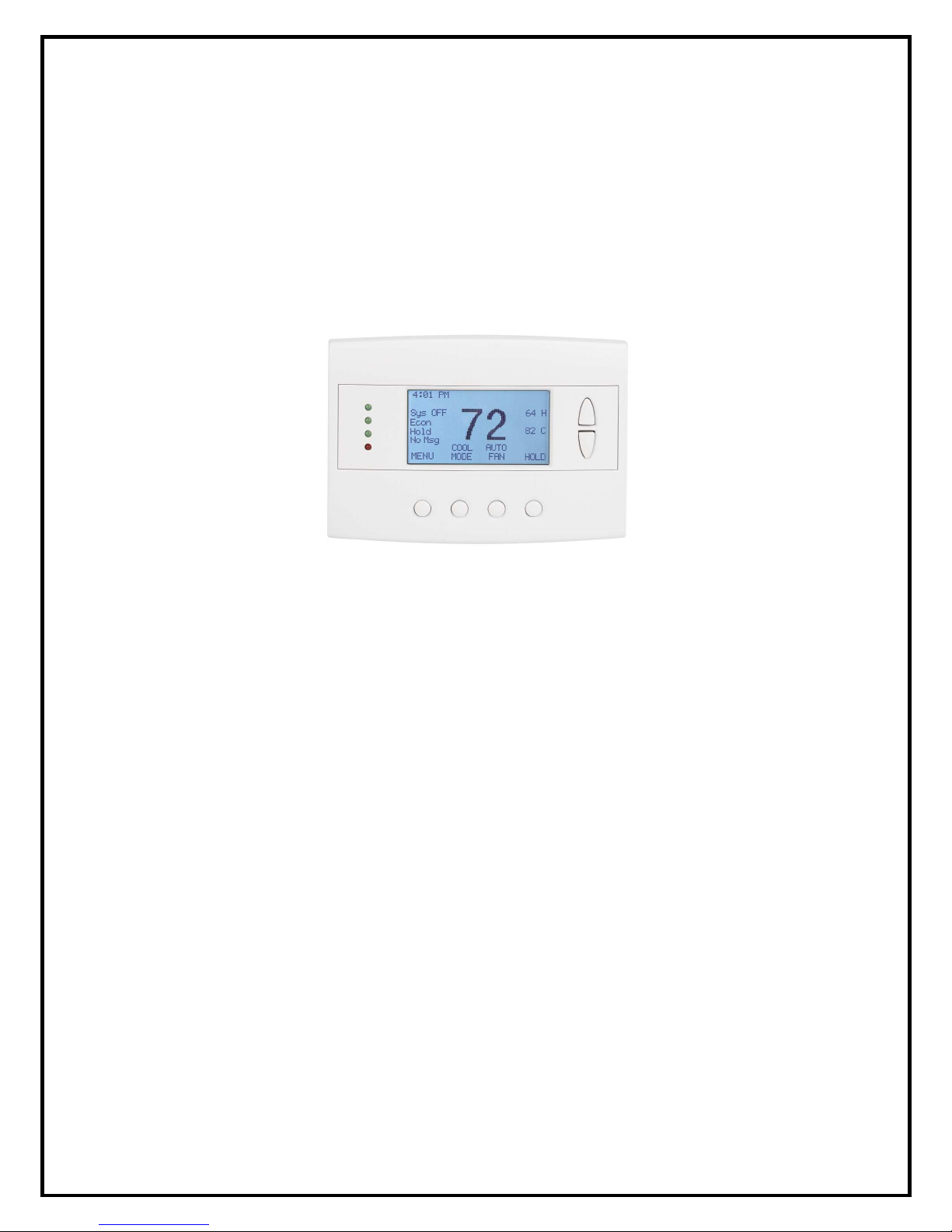
Model TR60
RS485 Thermostat
Installation Manual
DCN: 140-01761-01
3/21/09
*** IMPORTANT NOTICE ***
DO NOT USE THIS PRODUCT FOR BUILDING FREEZE PROTECTION! YOU ARE ADVISED TO
INSTALL A MECHANICAL FREEZE PROTECTION DEVICE ON YOUR SYSTEM FOR THIS PURPOSE.
Page 2
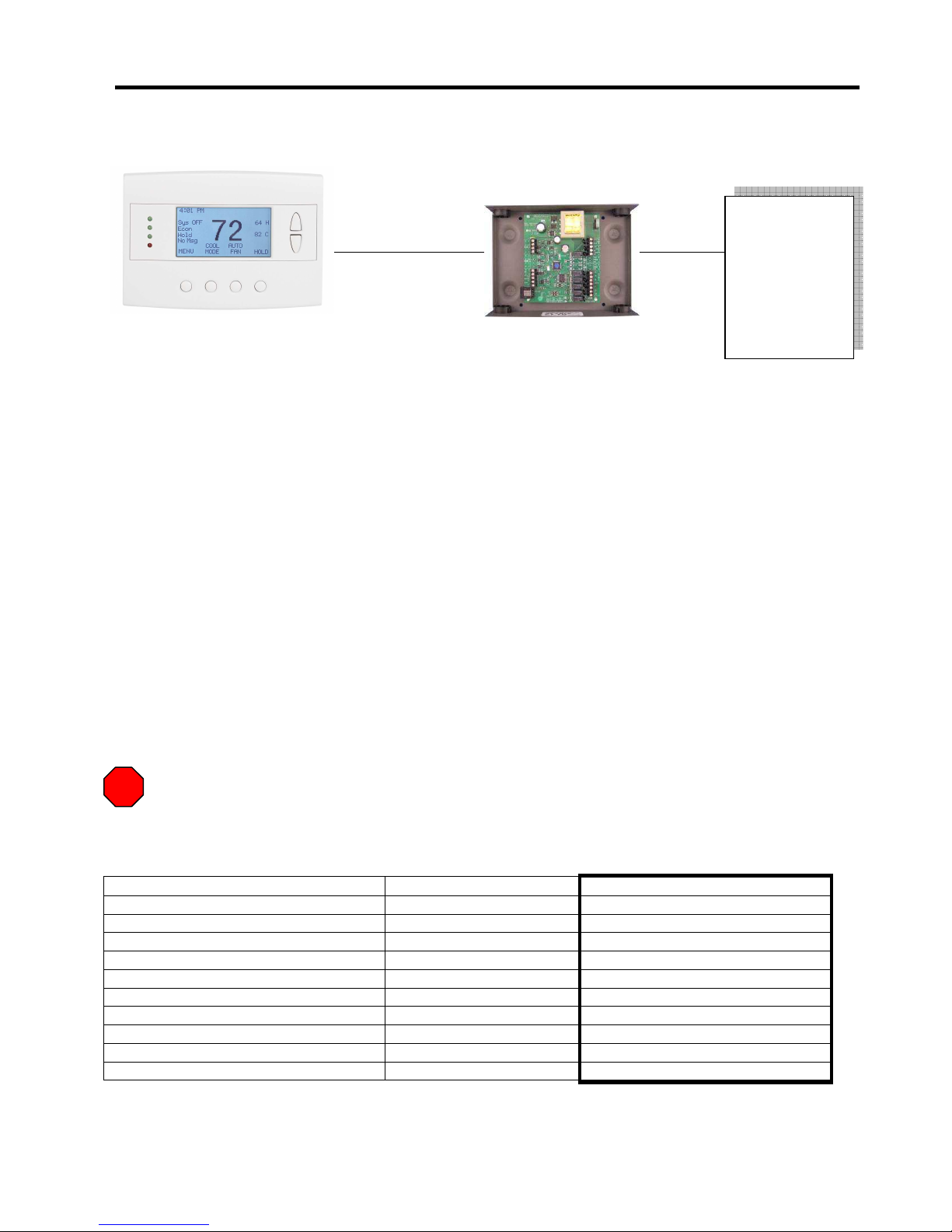
TR60 Thermostat Installation
The TR60 thermostat is a two part thermostat with a Wall Display Unit (WDU) and a HVAC Control Unit.
TR60 Wall Display Unit
Model: TS60 Model: ZCV1
4 Wire
Thermostat wire or
Cat 5 wire
Install theTR60 Wall Display Unit (WDU) on the wall in the traditional thermostat location. The HVAC
Control Unit is typically installed at the HVAC mechanical system location, but it can be installed anywhere
in the wiring between the WDU and the HVAC system.
Wiring
Retrofit installations
The Wall Display Unit replaces the traditional thermostat. The existing thermostat wiring can be used (4
wires required). Install the TR60 WDU at the thermostat end and simply cut the cable at the desired
location of the HVAC Control Unit and connect it in the line. 4 wires are required between the WDU and
HVAC Control Unit and typically 5 wires are required between the HVAC Control Unit and the HVAC
system. Heat Pump and Multistage systems may require additional wires between the HVAC Control Unit
and the HVAC System. Consult your HVAC system wiring diagram.
New Construction
For new installations, prewire the thermostat location back to the mechanical HVAC system with either
thermostat wire, 5 conductor, (18-20ga) or Cat 5 cabling. The TS60 WDU wires to the HVAC Control Unit
with this cable. The HVAC Control Unit wires to the HVAC system with thermostat wiring, typically 5 wire,
18-20Ga. Heat Pump and Multistage systems may require additional wires between the HVAC Control
Unit and the HVAC System. Consult your HVAC system wiring diagram.
STOP
BEFORE REMOVING THE OLD THEMOSTAT! Write down connections!
Be sure to write down the existing wiring connections to the old thermostat. Label the wires with the
thermostat connection. Refer to these when connecting the HVAC Control Unit to the HVAC system.
Old Thermostat Terminal Marking Typical Wire Color Your Wire Color
C or B (24V common) Blue or Black
R (or RH for split heating systems) Red from heating system
RC (for split cooling systems) Red from cooling system
G Green
W or W1 White
W2 Brown
Y or Y1 Yellow
Y2 Black or Blue
O (heat pump system only) Orange
B (heat pump system only) Brown or Blue
Caution: Thermostat wiring color codes are not standardized beyond simple 5 wire systems. Do
not rely on the color of the wire to determine function. Check it and write it down!
TR60 HVAC Control Unit HVAC System
5 Wire
minimum
Thermostat
wire
DCN 140-01761-01 3/21/09
2
Page 3
Wall Display Unit Installation
For retrofit installations, install the WDU at the existing thermostat location. You may reuse the existing
thermostat wiring (4 wires required).
For new installations, be sure to locate the WDU in a location for best temperature sensing in the area to
be controlled. Avoid these locations:
• Outside walls
• Drafty locations
• Direct sunlight exposure
• Near HVAC vents
• Corners or behind doors
Install the WDU
• Mark the location of the installation holes
• Install the screw anchors
• Run wiring through the back plate
• Install the back plate on the wall with the screws provided.
• Connect wiring to terminals. CAUTION! Double check your wiring. Mis-wiring the WDU can
result in damage to the unit.
• Write down the terminal wiring colors for connecting the WDU cable on the HVAC Control Unit
end.
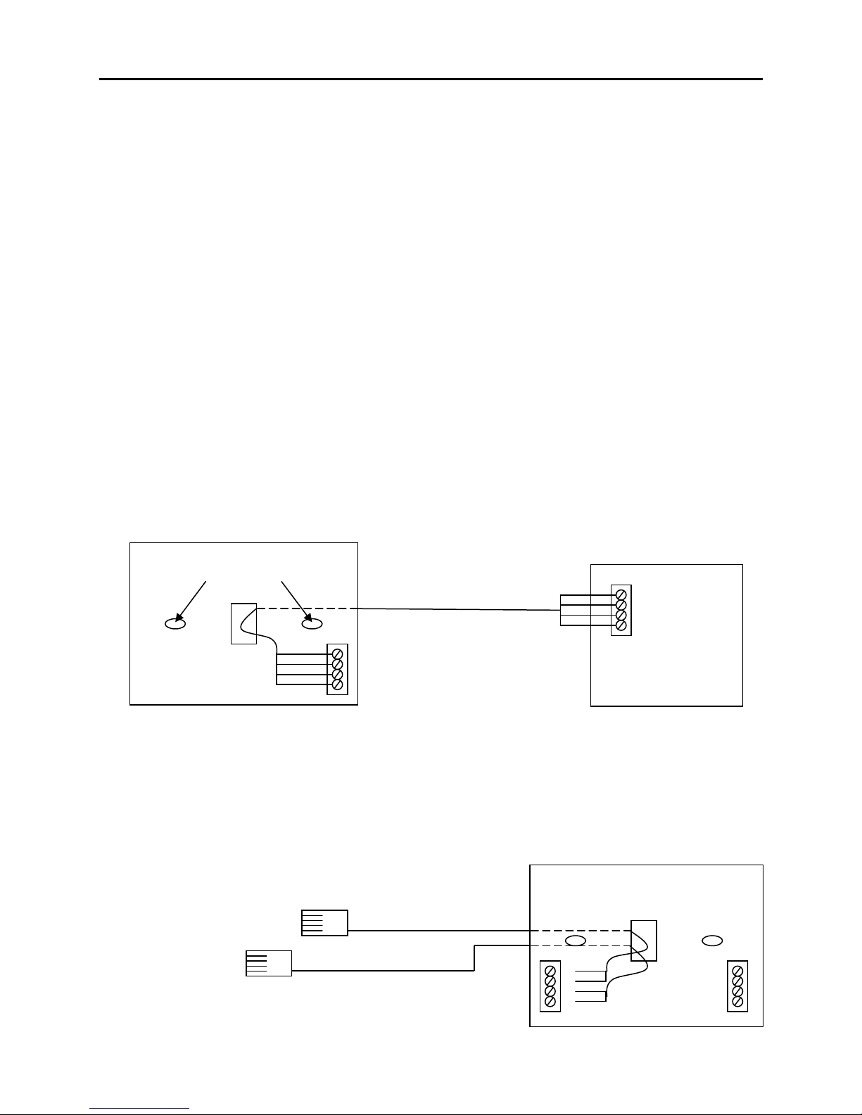
WDU Wiring to HVAC Control Unit
Wall Display Unit
Back Plate
Model: TS60
Mounting holes
Control Unit
G
+V
C
D
Remote Sensor Connection
Two remote sensors can be connected to the TR60 Wall Display Unit.
• Sensor S1 will replace the internal sensor
• Sensor S2 will be averaged with the internal sensor
or Sensor S1 if attached
• Use only RCS 10K Thermistor style sensors
Remote Temp Sensors
Model RTS3 or RTS4
S2
S1
Note the wire color connections.
4 wire connection is required back
to the HVAC Control Unit. Existing
thermostat wiring can be used.
For new construction, thermostat
wire or Cat 5 wire can be used.
Remote sensor wiring is non-polarized.
Remote Sensors
S1
S1
S2
S2
HVAC Control Unit
WDU
G
+V
C
D
Model: ZCV1
Wall Display Unit
Back Plate
DCN 140-01761-01 3/21/09
3
Page 4
HVAC Control Unit Installation
GND G
+12VDC +V
CLOCK C
DATA D
+12V
GND
DATA
CLK
can be used.
Location and Mounting
Install the HVAC Control Unit in a protected, convenient, indoor location near the HVAC system or in a
service accessible area such as an equipment closet or garage.
Mount the HVAC Control Unit in a vertical position on a wall or sturdy structural member. The unit may be
mounted on the HVAC system but care should be taken to avoid hot burner sections or high vibration
areas.
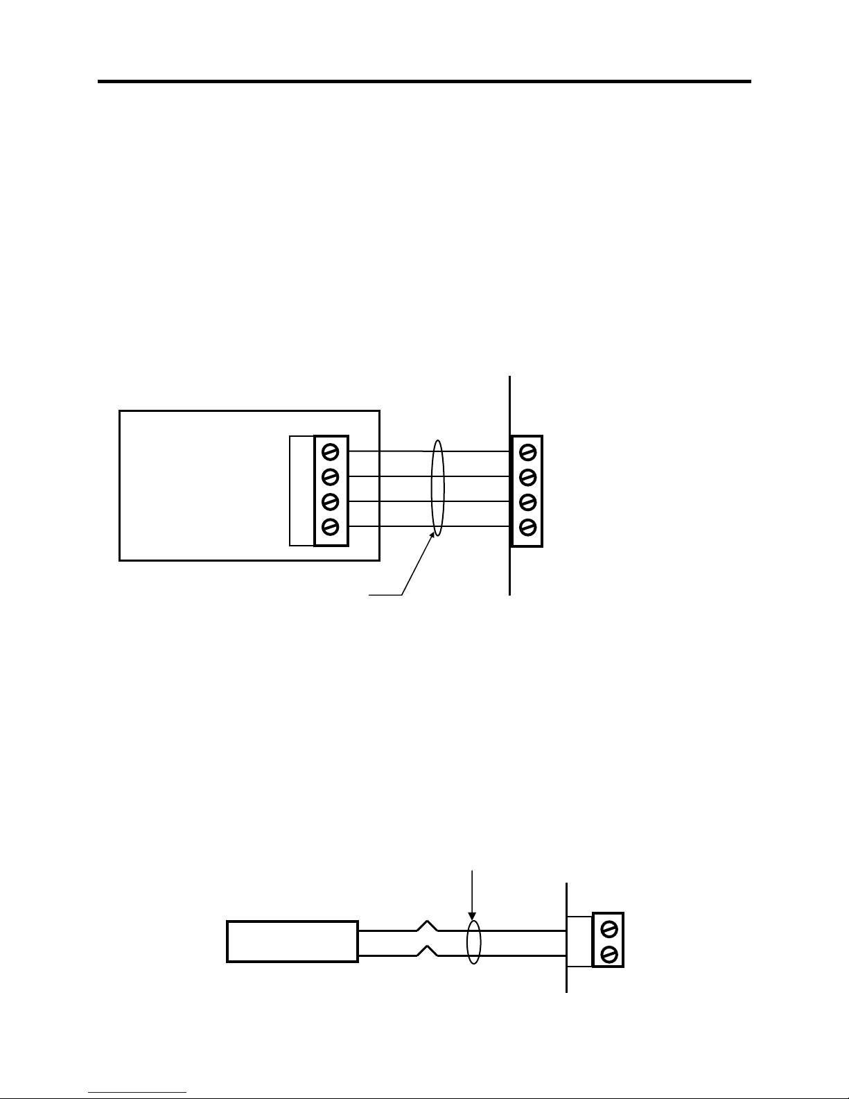
Wall Display Unit Connection
Wire specification: 4 conductor, 18/20Ga thermostat wire or 22Ga twisted pair or Cat 5 wire (preferred)
Connect the Wall Display Unit to the HVAC Control Unit by four wires. In retrofit applications, the existing
thermostat wiring may be used, however, for best results and in new construction, a Category 5 twisted
pair cable is recommended.
TR60 WALL DISPLAY UNIT
Standard Thermostat Wire or Cat 5 cable
Standard thermostat Wire color code
Ground: Green
12VDC: Red
Clock: Yellow
Data: White
Preferred Cat 5 Wire color code
Ground: Brown pair (twisted together)
12VDC: Blue Pair
Clock: Green Pair
Data: Orange Pair
CAUTION! Do not mis-wire the Wall Display Units – damage may result. Check the wiring before
applying power to the HVAC Control Unit.
TR60 HVAC CONTROL UNIT
WDU
Zone 1
Outside Temp Sensor Connection
Wire specification: 2 conductor, 22Ga twisted pair or Cat 3/5 wire (preferred)
Model OS5
Outside Temp Sensor
DCN 140-01761-01 3/21/09
Black
Red
Sensor wiring is not polarized.
4
TR60 HVAC CONTROL UNIT
S1
OS Sensor
S1
Page 5

RS485 Network Connection
The RS485 communications port is a 2 wire (D+ and D –) plus ground, half-duplex network connection.
Wiring options are direct to a host com port or wired to a RCS RS485 hub to allow star or homerun wiring.
Host System
RS485 port
12V
Gnd
D+
D -
Always wire + to + and – to –, regardless of the D+/ D- or A/B or TX/RX labels.
Up to 4000 ft
RS485 Wiring Note
RS485 Wiring Methods
The HVAC Control Unit can be wired by three methods:
1. Direct connection to RS485 Host com ports (as above)
2. Multi-drop (daisy chained) to other thermostats/devices
3. Homerun wired to an RCS Star Wiring Hub.
Multi-drop Wiring
Host System
RS485 port
12V
Gnd
D+
D -
Cat 5 cable recommended
RS485
Gnd
D+
D -
RS485
Gnd
D+
D -
Star Wiring Hub
CommStar Model CS308 or
Model 8AH485 8 Channel Star RS485 Hub
RS485 Port
RS485 Port
RS485 Port
RS485 Port
RS485 Port
RS485 Port
RS485 Port
RS485 Port
Cat 5 cable recommended
Each TR60 HVAC Control Unit is homerun wired to the Star Wiring Hub
HVAC Control Unit
RS485 Port
HVAC Control Unit
RS485 Port
HVAC Control Unit
RS485
Gnd
D+
D -
RS485
Gnd
D+
D -
HVAC Control Unit
RS485 Port
HVAC Control Unit
RS485 Port
100 ohm line
termination resistor
recommended on
last device (>100ft)
DCN 140-01761-01 3/21/09
5
Page 6

Connecting to RS232 Communications Ports
RCS Model 485PB 5-Port RS232 to RS485 Converter with power outputs.
PC or
Control System
DB9 Serial
Com Port
5 Port
RS485
Hub
Standard PC serial cable (incl)
(DB9 to DB9)
V
G
B+
A -
12VDC Power
Transformer (incl)
B&B Electronics Model 485DB9TB RS232 to RS485 Converter - 2 wire
PC or
Control System
Model 485DB9TB
DB9 Serial
Com Port
+12 G G TD(B) TD(A)
USConverters Model RS485 RS232 to RS485 Converter – 2 wire
PC or
Control System
DB9 Serial
Com Port
Model RS485
+5V
G
DD+
Connecting to USB Ports
Several companies make USB to RS485 Converters.
B&B Electronics
Model 485USBTB-2W
USConverters
Model US485MIO
Model USB485CAB
HVAC Control Unit
RS485
Gnd
D+
D -
HVAC Control Unit
RS485
Gnd
D+
D -
HVAC Control Unit
RS485
Gnd
D+
D -
DCN 140-01761-01 3/21/09
6
Page 7

Power Connection
The TR60 HVAC Control Unit requires 24VAC power. Power is provided from the HVAC system or by an
external transformer (not supplied). Do NOT connect the HVAC system power if you are connecting an
external power transformer.
Power
24C C
24R R
[or]
Standard
C
R
W
W2
G
Y1
Y2
Alternate power input.
External Transformer
24VAC 40VA
24V Com
24V Return
HVAC System
Connect only one
power source!
Vent Damper Wiring
Wire specification:
RD Series dampers: requires 2 conductor cable
RDM Series dampers: requires 3 conductor cable
Recommended wire: 18/20GA thermostat wire
Dampers
Vent Damper output supports either two wire (normally closed, power open/spring return) or three wire
dampers (power open, power close).
The vent damper output is 24VAC, 1 A max.
RD Series 2 Wire Dampers
24V R
24C
PWR
24R
24C
Vent
NC
Damper
NO
Yellow
Yellow
Normally Closed Damper
Power Open
Spring close
RDM Series 3 Wire Dampers
24V R
24C
PWR
24R
24C
Vent
NC
Damper
NO
1 Com
2 Open
3 Close
Power Open/Close Damper
Power Open (24V on 1-2)
Power Close (24V on 1-3)
DCN 140-01761-01 3/21/09
7
Page 8

HVAC System Connection
RH 24V
W2/CO
Y1 COMP
W1 Heat
W2/CO
Y1 Comp
The TR60 HVAC Control Unit connects to the HVAC system like a standard thermostat.
Standard Gas/Electric HVAC System Wiring
HVAC Control Unit
24C
PWR
24R
HVAC System
RC 24V
W1 HEAT
G FAN
Y2 COMP
Install jumper wire for power
from HVAC System
Standard HVAC System
THERMOSTAT CONNECTION
Blue
Red
White
Orange
Green
Yellow
Brown
C 24VAC COMMON
R 24VAC RETURN
W 1 Heat Stage 1
W2 Heat Stage 2
G Fan
Y1 Compressor Stage 1
Y2 Compressor Stage 2
JP1
Heat Pump HVAC System Wiring
HVAC Control Unit
HVAC System
24C
PWR
24R
RC 24V
RH 24V
G Fan
Y2 Comp
JP1
JP1: RH and RC Jumper
This commons both RH and RC for normal single transformer HVAC systems.
Cut JP1 jumper for separate RH and RC transformer systems.
NOTE: When jumper JP1 is cut, W1 and W2 are switched to RH. G, Y1
and Y2 are switched to RC.
Install jumper wire for power
from HVAC System
Heat Pump HVAC System
THERMOSTAT CONNECTION
Blue
Red
White
Orange
Green
Yellow
Brown
JP1: RH and RC Jumper . Do not cut.
Leave RH and RC connected for Heat Pump Systems
C 24VAC COMMON
R 24VAC RETURN
W1 Aux Heat
O/B Changeover (CO) Valve
G Fan
Y1 Compressor Stage 1
Y2 Compressor Stage 2
NOTE: Set correct Changeover
value operation for O (CO w/Cool)
or B (CO w/Heat) mode on
DIPSW1 on the control board.
DCN 140-01761-01 3/21/09
8
Page 9

HVAC SYSTEM SETUP
The TR60 must be configured for the correct HVAC system type. This is done by
setting the dipswitch, SW1, on the HVAC Control Unit.
You must know what type of HVAC system you have to correctly setup the thermostat. Determine the
following before you install the TR60. Check your HVAC system manual to verify.
• HVAC System Type: Standard Gas, Electric or Heat Pump system.
• HVAC System Fan Type: Gas or Electric
• Heat Pump System Changeover valve Type: Changeover with cooling or changeover with
heating.
For retrofit installations, the original thermostat settings and wiring may be clues to the proper settings. If
you are not sure, consult the HVAC system manual or contact a qualified service technician.
Setup Dipswitch SW1
Switch S1: System Type
Off: Standard gas/electric HVAC system (default)
On: Heat Pump System
Switch S2: S2 function is dependent on the setting of S1
If S1= Standard system
Then S2 = Fan Type
Off: Gas heating system (default)
On: Electric heating system
If S1= Heat Pump system
Then S2 = Changeover valve type (CO)
Off: CO/C Change over with cooling (default)
On: CO/H Change over with heating
Any change to the SW1 settings requires the
HVAC Control Unit to be power cycled (Off/On).
You can view and confirm the system setup in the Wall Display Unit’s Main Menu “Thermostat Info”
screen.
Additional setup options and operational preferences are available in the “User Settings” and “Installer
Settings” menus accessed from the Wall Display Unit.
Refer to the “Installer Settings” document from details of these optional settings.
Off On
S1
S2
S1 S2 OFF S2 ON
STD GAS ELECT
HP CO/C CO/H
Setting SW1 correctly is
required for proper system
operation.
DCN 140-01761-01 3/21/09
9
Page 10

SYSTEM CHECKOUT
It is strongly recommended that you hook-up and run a simple bench test before installing the TR60
thermostat. Not only will this save you time in system checkout but will also familiarize you with the TR60
operation.
Quick Test
NOTE: Before power up, set the dipswitch, DIPSW1, to ALL OFF.
1. Connect the Wall Display Unit to the WDU input on the HVAC Control Unit with a 3 foot 4 wire cable.
2. Connect a 24VAC transformer to the HVAC Control Unit Power Input connector.
3. Plug the transformer into a power outlet
4. Verify Status LED is flashing.
5. Verify the WDU display comes on and shows the current temperature.
a. If no display or a “CF” display is shown on the WDU, double check your wiring.
b. Do not proceed until the current temperature is displayed on the WDU and communications
between it and the HVAC Control Unit is OK. Any problems will result in a “CF”
(Communications Failure) display on the WDU.
6. Press the WDU Fan button on the WDU. The HVAC Control Unit Fan LED and relay should turn on.
7. Press the WDU Fan button again. The Fan LED and relay should turn off.
8. Press the WDU Mode button until Heat Mode is selected.
9. Press the Setpoint Up button until the setpoint is above the current temperature. The Heat LED and
relay should come on. (after any MOT delays, check WDU system status LED label)
10. Press the Mode button until OFF mode is selected. The Heat LED and relay will turn OFF.
11. Press the Mode button until Cool mode is selected.
12. Press the Setpoint Down button until the setpoint is below the current temperature. The Y1 and G
(Fan) LEDs and relays should turn on. (after any MOT delays, check WDU system status LED label)
13. Press the mode button until OFF mode is selected.
14. All LEDs and relays should turn off.
15. When you have successfully completed these tests, you have verified that the basic thermostat
functions are working correctly.
16. BEFORE INSTALLING THE THERMOSTAT, SET THE DIPSWITCH, SW1, TO THE CORRECT
CONFIGURATION FOR YOUR HVAC SYSTEM TYPE.
Communications Test with a PC
1. With the TR60 connected as above, proceed with connecting the HVAC Control Unit’s RS485 port to
a PC serial port (COM1) using a RS232 to RS485 converter (RCS Model 485DBTB or eqv).
Note: If you are not using an RCS RS485 to RS232 converter, be sure that your converter supports
automatic Send Data Control (required).
2 Confirm the thermostat address is 1 in the Thermostat Info screen. This is the default address. If not,
change in the Installer Settings/Network Settings menu item
3. Start Hyperterm terminal emulator program in Windows/Accessories/Communications/Hyper
Terminal.
4. Set Hyperterm communications parameters for COM1 to 9600 baud, no parity, 8 data bits, 1 stop bit
and NO flow control.
5. Set CAPS lock on (Commands are case sensitive).
6. Send the Request for Status command R=1.
Type “A=1 R=1” followed by the carriage return (cr).
7. Thermostat should respond with the R=1 status response showing temp, setpoint, mode and fan.
(A=00 O=1 Z=1 T=xx(current temp) SP=70 SPH=70 SPC= 74 M=0 F=0)
8. Set Mode to Heat. Type “A=1 M=H (cr)”.
9. WDU should change to show the new mode is “Heat”.
10. Set heat setpoint to 78 degrees. Type “A=1 SPH=78 (cr)”
11. WDU should change to show a setpoint update of “Heating Setpoint 78”.
12. If the WDU responds properly to these commands, proceed with final installation.
DCN 140-01761-01 3/21/09
10
Page 11

HVAC SYSTEM QUICK TEST
In the event that you have difficulty with the TR60 controlling the HVAC system, you can perform the
following quick test to confirm that the HVAC system is working correctly.
The TR60 HVAC Control Unit connects to the HVAC system at the normal thermostat connections on
the HVAC unit. Standard thermostat control of the HVAC systems consist of contact closures in the
thermostat. You can verify that your HVAC system is working correctly by duplicating these contact
closures by shorting across the proper terminals on the HVAC systems thermostat connection. Refer to
the following HVAC system example.
HVAC SYSTEM EXAMPLE
This is a simplified diagram of a Standard HVAC
System and Thermostat. The Thermostat operates
like switches to control the HVAC Fan, Heat, and Cool
functions.
FURNACE AND BLOWER UNIT
THERMOSTAT
FAN
COMP
Thermostat
R 24VAC
G FAN
W HEAT
Y COMP
C 24VAC COMMON
For Standard HVAC systems:
Go to the HVAC system’s thermostat connection terminals
Verify FAN operation by shorting across the R to G (Fan) terminals
• HVAC system fan should come on. (Caution: Delays may be
part of normal start up cycle, check HVAC system’s manual)
• If not check HVAC system power and fuses.
• If power is OK, HVAC system is NOT working correctly.
Verify HEAT operation by shorting across R to W (Heat) terminals (A Fan call is not necessary for gas furnaces)
• Heating operation should start. (Caution: Delays may be part of normal start up cycle, check HVAC
System’s manual)
• If not, check wiring, check 24VAC power is on R terminal. (measured across R to C).
• If power is OK, HVAC system is NOT working correctly.
Verify COOL operation by shorting across R to Y (Compressor) and R to G (Fan) terminals
• Cooling operation should start. (Caution: Short Cycle Protection 5 minute delays are normal
between calls and may delay start)
• If not, check wiring, check 24VAC power is on R terminal (measured across R to C)
• If power is OK, HVAC system is NOT working correctly.
If any of these checks fail, the HVAC system is not working correctly. Call an HVAC professional.
Heat Pump Systems are similar, but have an additional output for the changeover valve.
The basic fan and heating test are the same.
HVAC SYSTEM
STANDARD GAS/AC
FAN
RELAY
GAS
VALVE
COMP
RELAY
Outdoor
Condensing
Unit
24VAC
DCN 140-01761-01 3/21/09
11
Page 12

DCN 140-01761-01 3/21/09
12
GND
12V
CLK
DATA
Outside
Sensor
Vent Damper
RDM Series
shown
24C R
NC G
NO W
HVAC
System
G
12V
C
D
Green
Red
Yellow
White
75
G
+
C
D
WDU
Red
Black
24VAC
Power
Vent
Damper
HVAC System
Standard or Heat Pump
Set DIPSW1 to
Correct System Type
24V Com
24V
W1
W2
G1
Y1
Y2
Typical Thermostat Connection
24VC
24VH
Heat 1
*Heat 2
Fan
Comp1
Comp2
Outside
Temperature
Sensor
OS5
RC
RH
W1
W2/O
G
Y1
Y2
RC/RH Jumper JP1
Cut for separate Heating and
Cooling Transformers
Zone 1
Blue
Red
White
Orange
Green
Yellow
Brown
*Note: W2 = O/B (Changeover) when
Heat Pump System Type Selected
Red
White
STD HP
DIPSW1
Fuse
Mini ATO type
2A
S1 S2 OFF S2 ON
STD GAS ELECT
HP CO/C CO/H
S2
Typical Thermostat
Wiring Color Codes
180-01006-11
ZCV2 REV K
RCS
RCSRCS
RCS
Status LED
GND
D+
D -
RJ45
JACK
RS485
Network
Ground
Data +
Data -
RS485
Com Port
Alternate RS485 Connector
(8 Wire Modular Jack)
HVAC System Setup – Dipswitch SW1
DIPSWITCH HVAC SYSTEM SETUP
S1 Sets HVAC System Type Position
STD - Standard System Set S1 OFF (default) Left
HP - HP System Set S1 ON Right
S2 If S1= Standard System – Sets Fan Type
Gas System Set S2 OFF (default) Left
Electric System Set S2 ON Right
S2 If S1 = HP System – Sets Changeover (CO) Valve Type
O Mode: CO with Cool Set S2 OFF (default) Left
B Mode: CO with Heat Set S2 ON Right
Wall Display Unit
M
odel
TS60
RS485 RJ45
Connector Pinout
1 Data+
2 Data 3 NC
4 NC
5 NC
6 NC
7 NC
8 GND
12345678
Front View
1 24V Com
2 Open
3 Close
24VAC
24C B
24R R
Alternate power input.
External Transformer
24VAC 40VA
TR60
Wiring Diagram
S1
S2
Power from HVAC system.
Do not connect if using
external power transformer.
24V Com
24V
W1
O / B
G
Y1
Y2
Standard Heat Pump
HVAC Control Unit
Model ZCV1 Rev K
 Loading...