

Page 1

Product Guide | Issue 1.5 | The SM1020 GP Gateway/s Page 1
Product Guide | Issue 1.5 | The SM1020 GP Gateway/s Page 1
Product Guide | Issue 1.5 | The SM1020 GP Gateway/s Page 1
Product Guide
SM1020 GP Gateway
SM1020/W GP Gateway
Product Guide
| Issue 1.
5 | GP Gateway
Page 1
Product Guide
GP Gateway
Page 2

Product Guide | Issue 1.5 | GP Gateway Page 2
Introduction
The GP Gateway
Contents
1. INTRODUCTION
3
1.1 The SM1020 GP Gateway Range 3
1.2 Configuration 3
1.3 LED Status Information 4
2. SETTING UP THE GATEWAY
5
2.1 User Instructions 5
2.2 Screen Shot of the Configuration Page 5
3. CONFIGURATION
6
3.1 Units 6
3.2 Network Parameters 6
3.3 XML Parameters 6
3.4 Adaptor Control 6
4.
SPECIFICATION
7
4.1 Dimensions 7
4.2 Ordering Information 8
5. REVISION HISTORY
9
6. DISCLAIMER
10
7. CONTACT DETAILS
11
8. APPENDICES
8.1 Recommended RS-485 Practice 12
Page 3
Product Guide | Issue 1.5 | GP Gateway Page 3
Introduction
The GP Gateway
Introduction
1.1 The SM1020 GP Gateway Range
The RCS GP gateway has been designed as a cost effective solution to allow Bi-directional RS485
communications with RCS control products to and from IP based monitoring bureaus and other 3rd party systems.
The SM1020/W version provides Bi-directional ModBus communications with Williams Refrigeration Ltd, control
products to and from IP based monitoring bureaus and other 3rd party systems.
The GP Gateway/s provide the ability to:-
• Change controller operating parameters - enabling full parameter management.
• Communicate with 32 RS485 Devices.
• View real time controller status information.
The SM1020/W version supports the following Williams / LAE controller types:-
• AD2-5
• AD3-5
• WUMC2
• WUMC3
• WUBC2
• WUBC3
1.2 Configuration
The GP Gateway is simply configured by connecting a CAT5 patch cable between the Ethernet port of the
gateway and a laptop / PC with a static IP address in the range of 192.168.0.xxx.
Once the laptop / PC is configured, a web browser session can be started and the user can navigate to the
default IP address of the GP Gateway which is 192.168.0.101.
The web page that will be displayed allows the user to fully configure all IP settings and specify which controllers
are to be connected via RS485 to the device.
Once this has been completed the GP Gateway is ready to be installed.
Page 4

Product Guide | Issue 1.5 | GP Gateway Page 4
LED Status
The GP Gateway
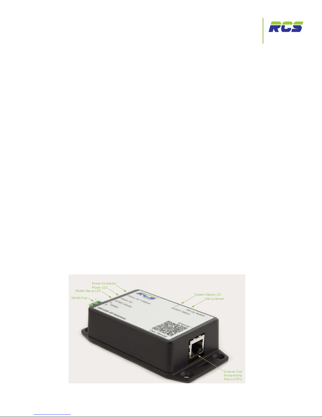
1.3 LED Status Information
Power LED (Green) – This indicator will be illuminated constantly when the 5vdc power supply is present.
RS485 Status LED (Red) – This indicator will initially be off, until valid communication activity is detected. Once
RS485 communication activity is present the LED will flash at an intermittent rate.
System status LED (Bi-Colour) – This indicator during normal operation will flash a mix of green and amber. If the
indicator displays permanent flashing green, RS485 communications has stopped.
Page 5

Product Guide | Issue 1.5 | GP Gateway Page 5
Setting up the Gateway
The GP Gateway
2 Setting up the Gateway
2.1 User Instructions
The GP Gateway has a default IP address of 192.168.0.101. The user can ensure that this address is loaded by
pressing the setup button on the side of the GP Gateway on power up for 5 seconds.
Please follow the procedure listed below to be presented with the GP Gateway configuration page. (fig. 1)
1. Connect a CAT5 patch lead into the Ethernet port of the GP Gateway.
2. Connect the CAT5 patch lead into the Ethernet port of the laptop / PC which will be used to configure
the GP Gateway.
3. Ensure that the laptop / PC is assigned a static IP address within the range of 192.168.0.xxx .
NOTE - care should be taken to ensure that this IP address doesn’t clash with any existing devices
resident on the network.
4. Power the GP Gateway off and on whilst holding the setup button in.
5. A standard web browser session can now be started on the laptop / PC. Type the default IP address of
192.168.0.101 into the browser address bar to display the GP Gateway setup screen (fig. 1)
2.2 Fig 1 - Screen Shot of the Configuration Page
Page 6

Product Guide | Issue 1.5 | GP Gateway Page 6
Setting up the Gateway
The GP Gateway
3 Configuration
3.1 Units
The 32 boxes under the heading of “units” allow the user to configure each of the controller unit numbers which
are to be connected onto the GP Gateway’s RS485 interface. Simply click into each box and type the controller
address. Please note the controller address should be entered in exactly the same format that it appears on the
controller.
The SM1020/W variant also allows the user to enter three characters of text preceding the unit number e.g
JSR1.0. - where JSR stands for J.Sainsbury Restaurant. This text will be included within the XML string that is
supplied to the monitoring bureau, and can aid in the physical location of a particular device.
Once all unit addresses are entered simply click the “Apply” button to save the configuration. This action will
cause the GP Gateway to restart. Please note that the transmission of xml data will commence after a period of 2
minutes following a restart.
3.2 Network Parameters
To assign the GP Gateway a static IP address simply click into the desired field and type the required address. If
the “use DHCP” field is checked, the GP Gateway will automatically request an IP address from the network
DHCP server. Please note:- If DHCP has been selected and the user subsequently wishes to re-enter the
configuration page this can be achieved by following the same steps as defined at the start of this document. Any
changes should be followed by clicking the “Apply” button to save the changes. This action will cause the GP
Gateway to restart.
3.3 XML Parameters
The values within the “XML Port” and “XML Password” are automatically populated on power up. Care should be
taken if the user wishes to change these values from the defaults. Any changes should be followed by clicking
the “Apply” button to save the changes. This action will cause the GP Gateway to restart.
3.4 Adaptor Control
If either the “restart” or “Reload Factory Settings” boxes are checked and “Apply” is subsequently clicked these
actions will immediately take effect, and the GP Gateway will restart.
Page 7

Product Guide | Issue 1.5 | GP Gateway Page 7
Specification
The GP Gateway
4 Specification
Ethernet Interface: 10/100 Base-T.
External Power supply: (Supplied)
AC 240v 50/60Hz <0.2A
DC 5V ± 5% <0.5A
EMC: EN 55014-1:2006 A2
Weight: 65 Grams (Excluding PSU)
Size: 110mm (L) x 57mm (W) x 26mm (D) – Inclusive of mounting
flanges.
Ventilation: No requirement for forced air cooling.
Operating temperature range: +5 ˚C to +50 ˚C
Operating Humidity: 80% Maximum
Class 2 Insulation: No protective earth is required.
Product Origin: Designed and manufactured in the UK
4.1 Dimensions
Page 8

Product Guide | Issue 1.5 | GP Gateway Page 8
Ordering Information
The GP Gateway
4.2 Ordering Information
Part Number Product Name Description
SM1020 GP Gateway General Purpose RS485 to IP Protocol Converter
SM1020/W GP Gateway for use with
Williams refrigeration units
General Purpose ModBus to IP Protocol Converter for
Williams / LAE controllers
Page 9

Product Guide | Issue 1.5 | GP Gateway Page 9
Revisions
The GP Gateway
5 Revision History
Issue 1.4 03/06/2014 SL Additional information
added within section 3.1
Issued for customer distribution
Issue 1.5 03/11/2016 SL Contact details amended Issued for customer distribution
Revision Date Author Amendments Comments
First Draft 02/02/2013 DS First Draft Issued for internal review
Issue 1.0 17/06/2013 DS Agreed content/format Issued for customer distribution
Issue 1.1 28/06/2013 DS Image alteration Issued for customer distribution
Issue 1.2 16/01/2014 SL Additional information
added for Williams variant
Issued for customer distribution Issue 1.2 16/01/2014 SL Additional information
added for Williams variant
Issued for customer distribution
Issue 1.3 29/04/2014 SL Appendices Added Issued for customer distribution
Page 10

Product Guide | Issue 1.5 | GP Gateway Page 10
Disclaimer
The GP Gateway
6 Disclaimer
To allow for design and specification improvements, the information contained within this document is subject to
change at any time without prior notice. RCS Energy Management shall not be liable for any errors or omissions,
for incidental or consequential damages either directly or indirectly resulting from the misuse of this product or
associated document.
Page 11

Product Guide | Issue 1.5 | GP Gateway Page 11
Contacts
The GP Gateway
7 Contact Details
RCS Energy Management
30 Kingfisher Court
Hambridge Road
Newbury
Berkshire
RG14 5SJ
UNITED KINGDOM
Tel: +44 (0) 1635 231600
Fax: +44 (0) 1635 231699
Email: sales@rcsenergymanagement.co.uk
Website: www.rcsenergymanagement.co.uk
RCS Energy Management is a trading name of Maxey Moverley Ltd.
Page 12

Product Guide | Issue 1.5 | GP Gateway Page 12
Appendices
The GP Gateway
8 Appendices
Appendix 1
8.1 Recommended wiring Practice for RS-485 Networked Devices.
Introduction
RS-485 transmits digital information between multiple locations. RS-485 is designed to transmit this information
over significant lengths, and 1000 meters are well within its capability. The distance and the data rate with which
RS-485 can be successfully used depend a great deal on the wiring of the system. RCS guidelines and
recommendations are provided within this document to ensure robust and reliable RS-485 networks.
Cable
RS-485 is designed to be a balanced system. Simply put, this means there are 2 wires, (other than ground), that
are used to transmit the signal. The system is called balanced, because the signal on one wire is ideally the exact
opposite of the signal on the second wire. In other words, if one wire is transmitting a high, the other wire will be
transmitting a low, and vice versa.
Although virtually any cable is capable of transmitting RS-485 signals, good wiring practice dictates that
TWISTED PAIR type cable is used.
As its name implies, a twisted pair is simply a pair of wires that are of equal length and are twisted together.
Using an RS-485-compliant transmitter with twisted-pair wire reduces two major sources of problems for
designers of high-speed long-distance networks: radiated EMI and received EMI.
RCS suggest the use of Belden type cable (or similar) such as 9501 / 2, with a characteristic impedance of 120
ohms. The RCS SM1020 gateway devices have termination resistors incorporated, however an end of line
terminator (120 Ohms) is recommended to be fitted on the last device on a zone. The two wire RCS system is
polarity conscious and the + - connections must remain consistent throughout the network.
Maximum Number of RS-485 controllers on a Network
RCS system manager (RS-485) devices and gateways are provided with 1, 4 or 8 channels (Zones) of RS-485.
Each one of these zones can accommodate 32 individual control devices.
It is good practice to ensure that cable lengths are kept to the minimum required without compromising network
integrity. The wiring configuration should be of a Multi-Drop (daisy chain) fashion whereby a single twisted pair
cable is terminated at the system manager / Gateway and run to each control device in turn using either the onboard “in and out” RS-485 connectors or the supplied communications terminals as in the case of Williams
devices, Eden Controller and pack controllers etc. To avoid impedance mismatches and signal reflections and
distortions a Star Point wiring configuration must not be used.
 Loading...